warwick.ac.uk/lib-publications
A Thesis Submitted for the Degree of PhD at the University of Warwick
Permanent WRAP URL:
http://wrap.warwick.ac.uk/110523
Copyright and reuse:
This thesis is made available online and is protected by original copyright.
Please scroll down to view the document itself.
Please refer to the repository record for this item for information to help you to cite it.
Our policy information is available from the repository home page.
THE PROCESSING, MICROSTRUCTURAL EVALUATION
AND MECHANICAL PROPERTIES OF SiC DISPERSOID
REINFORCED Si3N4 COMPOSITES.
A thesis submitted for the degree of DOCTOR OF PHILOSOPHY
of the University o f Warwick by
STEPHEN MARTIN KETCHION
January 1992
ABSTRACT
A range of composites have been prepared by dispersing various sources of SiC whiskers and platelets into a Si3N4 based matrix intended for high temperature applications. The main objective was to improve the fracture toughness of the Si3N4 monolith without any detrimental effect on other properties such as the excellent high
temperature deformation behaviour. The matrix composition was tailored so that the intergranular phase formed desirable crystallisation products within the Si3N4 - Si2N20 - Y2Si20 7 phase system. A slip casting technique was used to prepare the composites, in order to preferentially align the dispersoids, and conventional powder pressing methods were used to achieve a random distribution of dispersoids.
Composites containing at least 30 weight % dispersoid content were fully densified using ABB Cerama's glass encapsulated HIP process. The resulting
composites showed steadily increasing fracture toughness values with increasing SiC content, although the maximum increment was only approximately 30%. Platelet containing composites had slightly higher values than composites containing a similar volume fraction of whiskers, although there was a significantly lower fracture strength in the former. A microstructural survey of the materials indicated that the mechanical properties were influenced by the dispersoid / matrix interfacial characteristics. Fracture surfaces of the platelet containing composites showed there was significant debonding at the interface, whereas the whiskers appeared strongly bonded to the matrix.
ACKNOWLEDGEMENTS.
I wish to thank Professor S.B .Palmer for the provision o f laboratory
facilities at the University, Rolls -Royce pic for financial support and Dr. A. Hepworth
for access to laboratory facilities at T and N Technology Ltd, Rugby.
I am especially grateful to Professor M.H.Lewis for guidance and advice
throughout this research programme. I am also grateful for the technical advice of Dr.
G. Leng-Ward and the helpful discussions with my former research colleagues, Markys
Cain, John Femie, John Lumby, Dr. V.S.R. Murty, Mark Pharaoh, Kevin Plucknett and
Olwen Pullum.
I would like to thank the departmental technical staff, especially Gerry
Smith and Steve York for their expertise and tuition in electron microscopy, and Dan
Lee, Pat Beecroft and Dave Hammond for assistance in the mechanical workshops.
My special thanks go to my wife Angela for her patience, understanding
and support over the last few years. 1 would also like to take this opportunity to thank
ii-CONTENTS
-1-Abstract >
Acknowledgements ü
CHAPTER ON E : INTRODUCTION. 4
1.1. Engineering Ceramics. 4 1.2. The Composite Approach. 7 13. Programme Objectives. 10
CHAPTER TW O : A REVIEW O F TH E PROCESSING, TOUGHENING MECHANISMS AND PROPERTIES OF DISPERSOID REIN FORCED CERAM IC COM POSITES.
2.1. Processing of SijN4 Based Composites. 11
2.1.1. Introduction. 11
2.1 3 . The Si - Y - O - N System. 12 2.1 3 . Slip Casting. IS 2.1.4. Growth of SiC Whiskers. 17 2.13. Fabrication Techniques. 17 a) Reaction Bonded Si3N4 Ceramics. 18 b) Hot Pressed Si3N4 Ceramics. 18 c) Pressureless Sintering of Si3N4 Ceramics. 18 d) Hot Isostatic Pressing of Si3N4 Ceramics. 19
2.2. Toughening Mechanisms. 22 2.2.1. Crack Bridging Mechanisms. 25
a) Interface Debonding. 28
b) Toughening. 28
2.2.2. Crack Deflection. 32 a) Crack Deflection Theory. 32 b) Comparison of Experimental Work with Theory. 33 2.2.3. Microcracking. 37 2.2.4. Crack Branching. 38
2 3 . Properties of SiC Dispersoid Reinforced Si3N4 Ceramics. 40 2.3.1. Room Temperature Mechanical Properties. 40 2.3.2. High Temperature Deformation. 42 2 3 3 Oxidation of Si3N4 Ceramics. 45
-2-CHAPTER TH REE : EXPERIM ENTAL TECHNIQUES. 47
3.1. Composite Processing. 47 3.1.1. Slip Casting. 47 3.1.2. Densification. 31 3.1 3 . Hot Pressing. 32
3.2. Microstructural Evaluation. 33 3.2.1. Density Measurement. 55 3.2.2. X - Ray Diffraction. 56 3 .23. Optical Microscopy. 56 3.2.4. Scanning Electron Microscopy. 56 3.2.5. Transmission Electron Microscopy. 57
3 3 . Room Temperature Mechanical Testing. 57 3.3.1. Modulus of Rupture. 58 3 .3 3 . Vickers Hardness. 59 3.3.3. Fracture Toughness. 60
3.4. High Temperature Properties. 63
3.4.1. Creep. 63
3.4.2. Oxidation Resistance. 65
CH APTER FOUR : M ICROSTRUCTURAL EVALUATION. 66
4.1. Introduction 66
4.2. Characterisation of Dispersoids. 66 4.3. Material Compositions. 74 4.4. Optical Observations. 78
4.5. Densification. 84
4.6. Phase Evolution. 88 4.7. General Microstructure. 94 4.8. High Resolution Microscopy. 99
4.9. Summary. 110
CH APTER FIVE : ROOM TEM PERATURE M ECHANICAL 112 PROPERTIES.
5.1. Introduction. 112
5.2. Modulus of Rupture. 112 5.3. Vickers Hardness. 122 5.4. Fracture Toughness. 124 5.4.1. Experimental Results. 124 5.4.2. Fractography. 130 5.43. Comparison of Experimental Results with Theoretical Predictions 138
-3-CHAPTER SIX : H IG H TEM PERATURE PROPERTIES. M2
6.1. Introduction. 142
6 2 . High Temperature Deformation. 142 6 3 . Stress Rupture. 148
6.4. Oxidation. 133
6 3 . Summary. 138
CHAPTER SEVEN : CONCLUSIONS . 160
7.1. Introduction 160
7.2. General Conclusions. 160 7 3 . Specific Conclusions 163 7.4. Suggestions for future Work. 163
CHAPTER ONE.
INTRODUCTION.
1.1. ENGINEERING CERAMICS.
Improvements in the performance and efficiency of engineering devices
often requires the introduction of new and revolutionary materials. One such field is in
gas turbine engines where the cunent nickel based superalloys are approaching the
limits of their operational capabilities. Any further efficiency improvement to the levels
now sought, is limited by the small potential rise of operating temperature with
continuous development of already complex and expensive metals. Elaborate cooling
systems have been developed but this adversely affects the pressure ratio and thus
reduces the efficiency of the engine. At high temperatures ( > 1000°C) the metals
plastically deform and are chemically attacked by the atmosphere and corrosive fuel
elements. This has stimulated the development of high purity synthetic ceramics
which have the potential to replace these metallic components in a number of areas
because of an excellent combination of properties. Tablet. 1. The main advantages
offered by these engineering ceramics are :
1) increased operating temperature from around 1000°C to the region o f 1400°C,
which result in improved thermodynamic efficiency and consequently reduced fuel
consumption [ 1.2];
2) lower density components which will increase thrust to weight ratios and lower
centrifugal forces on rotating parts [3];
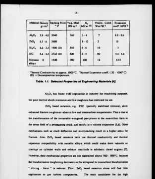
-5-Material Density g/cm 3
Melting Point ° C
Yng. Mod. GN m 2
K. MN m'w
Therm. Cond. W m ‘K 1
Expansion coeff. 10* K '1
AljO, 3.9 - 4.0 2040 360 3 - 4 7 6.9 - 8.6
z - o , 5 .7 -6 2680 8 - 1 2 2 10
Si,N4 3 .2-3.3 1900(D) 310 4 - 6 16 3
SiC 3 .2-3.3 2723 (D) 420 3 - 4 60 4 .5 -5 JO
Nimonic alloys
8 1320 200 100 12 12 J
Thermal Conductivity at approx. 1000°C. Thermal Expansion coeff. ( 20 - 1000° C) (D) = Decomposition temperature.
Table. 1.1. Selected Properties o f Engineering M aterials [4J.
A120 3 has found wide application in industry for machining purposes,
but poor thermal shock resistance and low toughness has restricted its use.
Z r0 2 based ceramics, e.g. PSZ (partially stabilised zirconia), show
enhanced fracture toughness values at low and intermediate temperatures. This is due to
the transformation of the metastable tetragonal precipitates to the monoclinic form in
the stress field of a propagating crack, and results in a volume expansion [5,6]. Other
mechanisms such as crack deflection and microcracking result in a higher stress for
fracture. Also, Z r0 2 based ceramics have low thermal conductivity and thermal
expansion compatibility with metallic alloys, which could make them valuable as
coatings on cylinder walls and exhaust manifolds in adiabatic diesel engines [7].
However, their mechanical properties are not maintained above 700 - 800°C because
the transformation toughening decreases as the tetragonal to monoclinic transformation
" driving - force " is reduced. Thus ZiOj based ceramics alone will find little
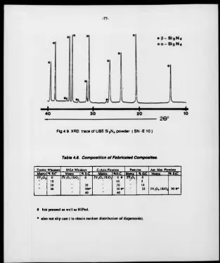
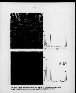
[image:9.355.13.327.9.373.2]
-6-temperature applications are Si3N4 and SiC based ceramics. They offer desirable
properties such as high specific strength, high elastic modulus and hardness, which
derive from their mainly covalent bonding, and also high creep resistance, low thermal
expansion and good oxidation resistance [8].
The U.K. was in the forefront of engineering ceramic research in the mid
-1960's, but this tailed off in the early 1970's partly because o f the limitation in
performance caused by inadequate quality of the ceramic products [9]. After the oil
crisis o f 1973, the U.S. government initiated its gas turbine program [10] and since
then, research and development expenditure has increased substantially [11].
Theoretical studies showed increases in gas turbine efficiency o f around 20% with the
introduction of silicon nitride components [12] and significant savings in fuel. Table
1.2. As a consequence, numerous market surveys [13,14] predicted large increases in
the use o f ceramic components by 1990 and beyond.
Type o f Engine % Reduction in Fuel O p erating T em perature °C
Gas Turbine (Automotive) 130 hp single shaft engine
27 1370
Gas Turbine (Truck) 330 hp two shaft engine
17 1240
Gas Turbine (Industrial) 1000 hp three stage engine
10 1370
Diesel engine Truck adiabatic turbo-compound 300 hp
22 1210
-7-Various national programs, such as the U.K's ACT program, have
investigated potential applications such as aerofoils, shroud rings and combustor
components in gas turbines [15,16], but these still remain in the research and
development stage. Both Nissan [17] and Daimler Benz [18] have demonstrated the use
of ceramics in automotive gas turbines. Parts fabricated include the piston cap, cylinder
liner spacer and the head plate. However, there has not been the rapid progress in
turbine component substitution as forseen in the early 1980's. Established applications
are mainly for low risk areas such as cutting tools and wear resistant parts. In the high
risk areas such as advanced gas turbine components, technical problems and cost
effectiveness are significant delaying factors. The main material problems responsible
a re :
a) the brittle nature of the monolithic ceramics, which results in an extreme sensitivity
to microflaws introduced during sintering, machine finishing or by contact stresses
when in service. This results in variable and thus unreliable mechanical properties.
Si3N4 is superior in this respect compared to SiC and thus it is given preference for
some applications;
b) the presence of sintering additives, which are needed during processing to achieve
full densification. These usually remain as an intergranular phase and effectively
control the high temperature time-dependent behaviour;
c) difficulty in the design and manufacture of complicated shapes, arising partly from
the problem of machining ceramics.
1.2. TH E CO M PO SITE APPROACH
Significant progress has been made towards solving some of the
-8-monolithic ceramics. However, a different microstructural design approach is needed in
order for these ceramics to be used as reliable components in mechanically demanding
engineering areas. One potential method o f overcoming the flaw sensitivity of Si3N4
based monolithic ceramics is by malting a composite. The principle o f adding high
modulus, high strength fibres within polymer matrices is well-established, but
developments using ceramic matrices have been restricted, until recently, by the
availability of suitable reinforcing materials. There are two different approaches in
forming ceramic composites. One has been to incorporate modest volumes of short
discontinuous 'fib res' and produce a composite which should to a great extent, reflect
the properties of the monolith, but with improved toughness. The other has been an
analogy with the development of conventional fibre composites, i.e. to utilize the high
strength and stiffness of the fibre, by forming a composite with a high volume fraction
of continuous fibres, and the matrix is of secondary importance but it imparts its high
temperature characteristics. However, developments of such Si3N4-based composites
have only been successful in producing composites with improved properties at low
temperatures [19].
Initial work on incorporating short, refractory and randomly oriented,
fibres , such as W, Mo and Ta, into a Si3N4 matrix, were unsatisfactory [20]. This was
because the matrix failed to protect the fibres from rapid degradation in oxidising
environments at high temperatures. Also, the metal fibres resulted in increased density
over the monolith, and stress caused by excessive thermal expansion mismatch.
Coating W wires with SiC increased work of fracture but they still had poor oxidation
resistance and there was a dramatic loss of strength above 800°C [21]. W ork on carbon
fibre reinforcement showed detrimental fibre/ matrix reactions as well as large tensile
-9-development of SiC fibres from polymer precursors [23] led to renewed activity,
particularly when high strength and fracture toughness were obtained for silicate glass
ceramics incorporating Nicalon SiC fibres [24]. The fracture toughness of a hot
pressed SiC - fibre reinforced Si3N4 was found to be significantly higher than the
monolith [25] but at high temperatures there were reductions in the strength because of
degradation of the fibres. Slurry coating and filament winding techniques have been
successfully applied to fabricate SiC / Si3N4 composites with moderate loading,
uniform distribution and a dense matrix. However, high strength and fracture toughness
have not as yet been achieved at high temperature [26]
Considering the difficulties encountered in the developments of fibre
reinforced Si3N4 materials, the use o f dispersoids such as particles, whiskers and
platelets as toughening constituents, offers an alternative. Theoretically, fibre
reinforcement shows significantly greater toughening increments over dispersoids, but
these gains are obtained at considerable cost, both in terms of the use o f expensive raw
materials and in the difficulty of fabrication and consolidation [27]. Dispersoid
reinforced composites can be processed by conventional powder processing techniques
[28] . For fibre reinforced composites, techniques such as lay up of fibres impregnated
by a matrix precursor, followed by pyrolysis and binder burnout, are typically used
[29] . Also, whiskers derived from rice hulls are now produced in reasonable quantity
and at costs well below that possible with polymer derived fibres or with CVD
monofilaments [30].
Whiskers are single crystals of stoichiometric compounds, thus there is
no tendency, as with polymer derived fibres, for recrystallisation, chemical reactions or
other detrimental processes. They are commonly grown in favourable crystal
have a typical Young's modulus of 580 GPa [31]. Thus, together with their intrinsic
thermal and chemical stability [31b], whiskers offer a good reinforcement potential for
high temperature ceramic composites.
I J PROGRAM M E OBJECTIVES.
The broad aims of this research programme were:
1) to fabricate a range o f fully dense and homogeneous SiC dispersoid reinforced Si3N4
composites, principally by hot isostatic pressing (HIP). Various different types and
sources of dispersoid were used, particularly whiskers but also particles and platelets.
These were dispersed into a tailored Si3N4 based matrix composition, which has been
shown to have desirable high temperature properties ;
2) to study the effect o f dispersoid additions on the crystallisation behaviour of the
matrix intergranular phase;
3) to study the microstructure and interfacial stability of the composites using optical,
electron microscopic and microanalytical techniques ;
4) to measure various mechanical properties of the composites as a function of volume,
type and orientation of the dispersoids, and to relate these results to the microstructural
features in older to gain an insight into the toughening mechanisns taking place in these
composites;
5) to examine the high temperature deformation, stress rupture and oxidation behaviour
-11-CHAPTER TWO
A REVIEW OF THE PROCESSING, TOUGHENING
MECHANISMS AND PROPERTIES OF DISPERSOID
REINFORCED CERAMIC COMPOSITES.
This chapter outlines the techniques used to process and fabricate Si3N4
ceramics, the mechanisms involved in toughening brittle monoliths and a review of the
properties o f SiC dispersoid reinforced ceramic matrices.
2.1. PROCESSING O F Si3N4 BASED COMPOSITES.
2.1.1. Introduction.
Normal metallurgical processing practice is inappropriate for ceramics
because of their high melting points or decompositional problems, and their resistance
to plastic flow. This processing constraint means Si3N4 ceramics are usually formed
by sintering, i.e. consolidation of pressed particle aggregates. Due to the very low rate
o f self-diffusion of Si3N4 , the sintering process is usually accelerated by additives,
typically MgO, A120 3 and Y20 3. These react with the S i0 2 present on the surface of
the initial a - Si3N4 powder [32] to form an intergranular liquid. The presence of this
liquid phase promotes rapid transport paths during densification by a solution -
reprecipitation mechanism [33 - 36], shown schematically in Fig.2.1. It also acts as a
solvent for the necessary a to P - Si3N4 conversion to take place. Both processes occur
simultaneously during the early stages of liquid phase sintering, with the a to P
transformation aiding in particle rearrangement [37]. Usually additional pressure must
Dense Si3N4-based ceramics are characterised by a multiphase
microstructure where P - Si3N4 forms the principal component and the amorphous
and/ or crystalline intergranular region forms the minor phase. This intergranular phase
largely controls the thermomechanical properties of the ceramic rather than the
primary Si3N4 component [38,39], Therefore, much research into high temperature
components is geared to optimising the level of sintering additive and tailoring the
glass composition for subsequent crystallisation.
Sintering and the resultant microstnicture evolution is a multistage and
complex process, dependent on many material and processing parameters such as
precise composition, quantity of surface S i0 2, a - Si3N4 grain size and shape,
presence of impurities, temperature and pressure. An overview o f progress in
microstmctural development o f a range o f monolithic Si3N4 materials can be found in
selected review papers [38,40,41].
2.1.2. The Si • Y • O • N System.
The key to high temperature performance is the ability to achieve
theoretical densification in a completely crystalline microstructure [38,42-44].
Crystalline phases retain their properties much closer to the eutectic temperature than
an amorphous phase, which softens and enables rapid diffusion of ions. The recognition
of a correlation between the loss of strength, loss of creep resistance and enhanced
oxidation at high temperatures, and the softening of the intergranular silicate phases
present in most Si3N4 based ceramics, has led to numerous attempts to control the
viscosity and volume of these phases. This is reflected in the experimentation with
different additive systems. The choice of the specific sintering additive is governed by :
-13-b) the softening temperature of any residual glass;
c) the ease of crystallisation of the intergranular glass into an oxidation resistant
phase.
Stable intergranular liquids result from the use of CaO, MgO, A120 3. NdjC^, LajOj
and Y20 3, and mixed combinations o f these. Y20 3 has the advantage of a high eutectic
liquid softening temperature, i.e. Y20 3 - SiOj at 1660°C, and thus has better potential
than other systems for high temperaure applications [43]. However, higher sintering
temperatures and pressures are required to achieve full densification.
The microstructural development and material properties o f Y20 3 -
containing Si3N4 based ceramics are sensitive to both the presence o f amorphous
residues and the type of crystalline phases present. Careful compositional selection is
required when preparing materials in the Y - Si - O - N system, Fig.2.2, so that a minor
phase is found which creates suitable densification kinetics during sintering and is
readily recrystallised to a structure retaining oxidative stability up to at least 1400°C.
Compositions within the Si3N4 - Si2N20 - Y2Si20 7 phase field are particularly suitable
in terms of ease of crystallisation, stability in oxidising environments, and the absence
of significant volume changes [46,47]. Optimisation of compositions within this phase
field, intended to minimise the intergranular amorphous component and enhance
O x id « Ad ditiv«
S u rfac« S ilk «
R g .2 .1 . Schematic drawing of th« solution - reprecipitation mechanism.
2Y«O , 4YN
-15-2.1.3. Slip Casting.
Once the composition of the matrix has been decided the starting
powders and dispersoids must be consolidated before densification. This can be done
by a number of methods, but slip casting offers the possibility of preferred whisker
orientation with little damage to the dispersoid. The slip casting process is strongly
influenced by the properties of the Si3N4 powder and sintering additive suspension, and
it is necessary to manipulate and control interparticle forces by an electrostatic method
( pH control ) [51-53], This technique also helps to ensure heterogeneities are
eliminated and are not reintroduced in subsequent processing steps.
When the ceramic powders are mixed in a polar liquid, counter - ions
i.e. ions o f opposite charge to the particle surface within the liquid, are attracted to the
charged particle surface. Those counter - ions which are tightly adsorbed to the surface
form the Stem's layer, which sets up an electrical potential due to the screening effect
of the counter - ions. The remainder of the counter - ions form a diffuse layer around
the particles ( Gouy - Chapman's layer ) the concentration of which decreases
exponentially with distance [54]. When the particles migrate through the liquid, a layer
of liquid molecules, called the lyosphere, remains bonded to the particle. The potential
at the boundary between the lyosphere and the free liquid is called the zeta potential
and this largely controls the rheological properties of the slip. Using a high solid
loading usually produces a viscous, flocculated slip because attractive forces ( largely
Van der Waals forces ) predominate. Adjusting the pH, influences the zeta potential,
and repulsive forces can be made to predominate, so breaking up agglomerates and
dispersing the constituents, i.e. deflocculation. Research is still taking place which can
give a predictive understanding of the sluny rheology, as affected by the interparticle
-16-The electrostatic stability o f multiphase aqueous Si3N4 slips, are strongly
influenced by the electrolytic effects of the sintering additives, necessary to promote
liquid phase sintering. Oxides like Y20 3 form positive counter ions by the dissociation
of their hydroxide in water.
Y 3* (OH)3 --- > YJ* ♦ 3 (O H )' ...2.1
Small concentrations of Y 3* ions i.e. 0.08mmol /1, have been found to
be sufficient to cause rapid flocculation of Si3N4 powders at a pH of 8 [SI]. This is
shown in the Schulze - Hardy rule 2.2, which indicates that the critical flocculation
concentration (cfc) depends strongly on the surface potential X, and the charge of the
counterions Z.
cfc = B X4 / A J Z2 ... 2 . 2 [SI]
where A = Hamaker constant
B = geometric constant
This shows that varying the concentration of the Y 3* or the Y containing sintering
aid, has a significant effect on colloidal stability and consequently a pH > 8 has to be
used for the electrostatic repulsive forces to break up agglomerates and disperse the
constituents. The interparticle forces can then be made attractive to form a stable slip
and then consolidated to form a powder compact by either tape casting, injection
moulding or slip casting. Slip casting is a relatively simple technique in which the slip
is poured into a mould and capillary action, due to the pores in the mould, withdraws
the filtrate from the slip. A low density cake is formed on the mould surface which can
be dried and densified using one of the fabrication routes mentioned later. Details of the
mechanism of filtration and kinetics of cake deposition can be found in selected papers
2.1.4. Growth o f SiC whiskers.
The main method of dispersoid reinforcement of the SijN4 ceramic was
the incorporation of SiC whiskers. These minute, high purity, single crystal fibres are
produced commercially by a vapour - solid ( VS ) mechanism, more conventionally
known as the rice - hull process [38,39]. Rice hulls are composed primarily o f cellulose
but also contain silica, and when they are heated in a coking furnace, the cellulose
decomposes to yield carbon. When this coked product is heated in the 1200°C to
1800°C range, a car bo thermal reaction occurs between the silica and carbon via the gas
phase, and crystalline particles and whiskers of SiC are formed.
Recently, the VLS process has been developed and refined for the
growth of SiC whiskers [60,61]. In this mechanism, V stands for Vapour feed gases, L
for Liquid catalyst, and S for Solid crystalline growth. The distinguishing feature of this
process is the presence of a liquid catalyst, such as a transition metal alloy. The catalyst
solution is a preferred site for deposition of C and Si atoms in the vapour feed, and
when it becomes supersaturated, SiC precipitates out. Whisker growth occurs at a rate
determined by the speed at which the gases are fed into the system to cause
supersaturation, and to a size proportional to the dimensions of the catalyst ball. It has
been reported that whiskers measuring 3 - 5 pm in diameter, 16 mm in length and with
an average tensile strength of 160 GPa can be grown [62],
2.1.5. Fabrication Techniques.
There are a variety of different fabrication routes which can be used in
order to produce dense Si 3N4-based components. The features of the main techniques
(a) Reaction Bonded Si3N4 Ceramics.
In this method silicon powder is consolidated by cold isostatic pressing
(CIP), slip casting or injection moulding, followed by nitridation at 1400°C over
several days. Only small dimensional changes occur during nitriding, so the process is
suited to mass production o f complex shaped components where little final machining
is required. However, RBSN has a relatively high porosity which has a detrimental
effect on strength and oxidation resistance. The density can be improved by following
the nitriding stage with Hot Isostatic Pressing ( HIP ).
(b) H ot Pressed Si3N4 Ceramics.
In this technique, the Si3N4, sintering aid and dispersoids are uniaxially
pressed in a graphite die using pressure, typically 20 - 40 MPa, at a temperature of
1650 - 1800°C [63]. The uniaxial nature of hot pressing promotes a certain degree of
anisotropy in component properties, due to the prefencd orientation o f the (3 - Si3N4
grains and dispersoids perpendicular to the pressing direction [64,65]. The technique is
limited in application because only simple shapes can be formed and diamond
machining of hard densified material is very expensive.
(c) Pressureless Sintering of Si3N4 Ceramics.
The need to produce densified complex shaped Si3N4 components
promoted the development of pressureless sintering. However, the presence of non
shrinking whiskers in the green body inhibits the bulk shrinkage of the sample, which is
needed to accommodate densification by sintering. The resistance to such shrinkage
caused by the stiff whiskers has thus frustrated the use of conventional pressureless
-18-
-19-pressure-assisted techniques are required.
(d) Hot Isostatic Pressing of Si3N4 Ceramics.
Hot isostatic pressing ( HIP ) is a fabrication technique that involves the
use of high isostatic pressures (100 - 300 MPa) and high temperatures (1650 - 1800°C),
to assist densification by sintering and mechanical consolidation. It is essentially a
combination o f hot pressing and cold isostatic pressing but offers som e potential
advantages for Si3N4 based ceramics [66]. These are :
a) higher pressures are applied than in hot pressing, which means lower temperatures
and shorter densification times are used;
b) theoretically dense composites can be obtained with less sintering aid;
c) fully isotropic properties can be obtained ;
d) complicated shapes can be made in a near net shape process.
The HIP process originated at the Battelle Memorial Institute, Ohio and
was developed for diffusion bonding of clad nuclear fuel elements [67]. O ne o f the first
industries where HIP was introduced as a productive tool, was in the tungsten carbide
industry, and applications such as the consolidation of high speed tool steel powders,
nickel - based superalloys and healing of defects in castings were introduced [69]. As a
result of increased temperatures and pressure capabilities of HIP equipment, the
process was introduced in the ceramic industry for the densification of powders. There
are two major routes for the HIP o f Si3N4 based ceramics [69].
a) a green state ceramic article is formed and then encapsulated prior to HIP.
b) the green state material is sintered until the surface connecting porosity is closed,
i.e. typically > 93% of theoretical density. The sintered part is then H IP without
-20-use of an impermeable barrier layer that totally envelops the ceramic during HIP. This
encapsulant layer prevents penetration o f the pressure transmitting gas into the ceramic
article. If gas ingresses into the component, e.g. from encapsulant failure, the gas
pressure acting within the interconnecting porosity o f the ceramic will counteract the
densification process.
HIP densification of SijN4 was first achieved by researchers at ASEA
[66,70 - 72J who placed a preformed body in an open-ended capsule of SiOj or
borosilicate glass. i.e. tubular encapsulation [70]. It was then placed in a conventional
furnace at 100°C and evacuated to 0.1 Pa for 8 hours using a vacuum pump attached to
the open end of the capsule. The capsule was then backflushed with nitrogen to
atmospheric pressure and sealed. Following sealing, the capsule was heated in a
furnace to 1250°C, at which point the glass softens and becomes deformable. The
temperature and pressure were then ramped up to their hold conditions, i.e. 1700 -
1800°C and 150 - 300 MPa, using either argon or helium as the pressurising gas. After
HIP, the encapsulant glass was removed by sandblasting. A further development of this
method, allowing slightly more complex shapes, involved packing the Si3N4 article in
SiOj powder within a Pyrex glass capsule, Fig.2.3. The use of an inner glass powder
that softens at a higher temperature than the capsule, allows the formation of an
intermediate composition / viscosity region between the two glasses. This was found to
be necessary because the Pyrex tends to run - off at temperatures in excess of 1000°C
and the inner silica powder will not soften until 1250°C. The desire to fabricate more
complex shaped parts, led to further investigations into methods o f near net shape
encapsulation via the use of a glass powder [73-80]. The article to be HIPed is placed in
the glass powder within a graphite crucible, Fig.2.4. A barrier layer o f boron nitride is
-21-Rg.2.3. Schematic Representation of A S E A Tubular Encapsulation [72].
-22-reaction occuring. The encapsulant melting is conducted under vacuum and full
pressure is applied when the melted glass has a suitable viscosity, i.e. a maximum of
106 poise. Glass powder bed encapsulation has been shown to be suitable for the mass
production of densified ceramics, with a maximum processing capacity of over 26,000
components in one HIP cycle [80].
The major disadvantage cited for the use o f HIP of ceramics, is the
relatively high cost. However, HIP is already an established fabrication route for the
removal o f porosity in WC - Co alloys [81,82], for the processing of Ti superalloys and
electronic ceramics [83]. ABB Cerama AB are presently operating HIP units, ranging
in volume from 3 to 600 litres, with the smaller units capable o f 2000°C .
HIP development of ceramics is still in its infancy, but the technique will
gain greater approval as costs are reduced and green state processing methods improve.
2.2. TOUGHENING MECHANISMS.
Engineering components fail at an applied stress below the calculated
critical applied stress because of the presence of microscopic flaws, produced during
the processing stage and/or during service. Inglis [84] considered such flaws as local
stress concentrators which have the effect o f magnifying the applied stress by 100 to
1000 times. To consider why some materials are more sensitive to flaws than others, a
fracture mechanics approach was adopted. Griffith's work on crack stability [83],
believed unstable fracture occurs when the energy loss when the crack propagates
-23-o f = | ( 2 E y ) / ( K c )] »'* ... 2 3
where o f = fracture stress E = Young's Modulus
Y = surface energy c = crack length
Other energy dissipative mechanisms, such as plasticity, exist during crack
propagation. Irwin suggested that crack propagation will occur provided the energy
release rate ( G ) exceeds the energy required to form the tw o new surfaces, i.e. when
G > 2 y [86]. Hence the modified Griffith equation o f ( 2.3 ) becomes
O f = [ ( E G e J A u c ) ] ' « ... 2.4
where Gc = the critical strain energy release rate or toughness.
The onset of fast fracture occurs when :
o f ( * c ) w = ( E Gc ) 1/2 ... 2.5
The right hand side of equation 2.5 depends on material properties only. Thus, the
term a r ( n c )xn , the critical stress intensity factor. Kc , is a material constant.
This term is more usually called the fracture toughness.
Brittle fracture may be resolved into into three distinct modes, Fig.2.5,
and thus Gc and Kc can be suffixed to describe the energy release in a specific mode of
crack propagation. When a crack propagates in a direction perpendicular to the applied
stress i.e. mode 1 Kc is denoted by Kk to indicate that this is the prevalent mode.
Si3N4 has a low Kk value and thus is very sensitive to flaws. This
-24-mode I mode II
crick opening mode sliding mode tearing mode
-25-sample of similar components. There are two different routes to achieve higher
reliability:
a) the flaw control approach;
b) the toughening approach.
In the first route the various processing flaws are controlled by identifying and
eliminating the dominant heterogeneity and the processing step responsible for it
[87,88]. In the second approach microstructures are created which impart sufficient
fracture resistance that the strength becomes insensitive to the size of the flaws [89].
There are a variety o f mechanisms that contribute to toughening, such as
process zone mechanisms, crack bridging mechanisms and crack deflection.
Transformation toughening is a process zone mechanism [90,91] caused by the
constraining effect of the residual strain field in panicles around the crack tip
undergoing phase transformation. As already mentioned, this temperature dependent
process is prevalent in zirconia based materials but not in Si3N4.
2.2.1. C rack bridging m echanisms.
Reinforcing phases that bridge a crack surface, can be divided into those
that are ductile and those that are brittle. Ductile toughened ceramics refers to metal
toughened ceramics (cermets) and rely on high toughness and ductility to allow metal
ligaments to exist and to contribute to toughness through plastic dissipation. Large local
residual stresses caused by thermal expansion mismatch, are capable of suppressing
local crack propagation and allow intact ligaments to exist behind the crack front
[92.93],
Crack bridging with brittle materials with a toughness similar to that of
-26-constants, weak interfaces or both. The classical example of the formation of a bridging
zone is seen in continuous fibre reinforced ceramics, where toughness is enhanced by
the extensive pullout of the fibres in this zone [94-98]. Tough ceramics like this exhibit
a typical stress / strain curve shown in Fig.2.6. In any analytical solution to these
phenomena, the role of key matrix and dispersoid properties needs to be addressed.
If the elastic constants o f the whisker are much larger than that of the
matrix, the crack tip stresses can be altered so that a crack travelling normal to the
whisker axis is deflected out of plane as it approaches the whisker [99]. However, in
the case of SiC reinforced Si3N4 , the elastic properties of the two phases are similar
i.e.Young's moduli are approximately 400 GPa and 300 GPa for SiC and Si3N4,
respectively. Also, the fracture toughness values for Si3N4 are in the range 4 to 6
MPa.m 1/2 versus 3 to 4.5 MPa.ml/2 for SiC. Thus deflection of the crack as it
approaches the interface due to differences in elastic properties appear to be negligible
in such systems.
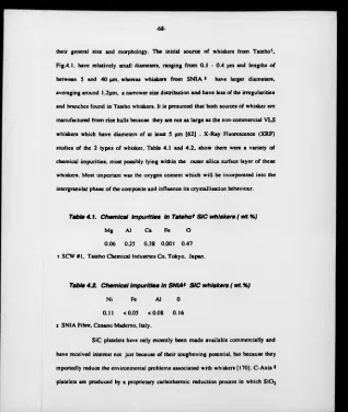
The second process which avoids whisker fracture, involves debonding
o f the whisker / matrix interface as the crack approaches or just reaches the whisker,
Fig.2.7. The magnitude of the toughening depends on the debond extent, the mode of
reinforcement failure and residual stress effects. Theoretical models have been
developed and compared to electron microscopy studies of the behaviour of dynamic
0V0
1
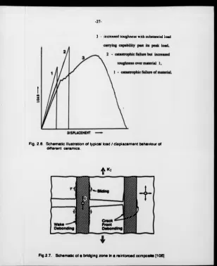
-27-3 - increased toughness with substantial load
Fig. 2.6. Schematic illustration of typical load / displacement behaviour of different ceramics.
V
1
[image:31.355.17.325.6.384.2]
-28-22.1a Interface Debonding.
For a matrix crack subject to mode 1 loading, the occurrence of initial
debonding rather than cracking into the whisker, is governed by the ratio of interface to
whisker fracture energies T j / T f and the whisker orientation, Fig.2.8. For SiC /
Si3N4 composites, T; / Tf should be < 1/3 to debond whiskers normal to the crack
plane. This prediction is independent of residual stress. Growth o f the initial debond
along the interface is influenced by the residual stress and whisker radius and it is most
noticeable in the crack wake [103,104].
Analysis of wake debonding for interfaces under residual tension, as in
SiC / Si3N4 composites, indicates that debond growth in the wake occurs when the
stress, t on the whisker reaches a critical value t*. given by :
t* = 2.2 E je , ... 2.6 [103]
where Et = Young's modulus for the whisker e, = misfit strain
When t > t*. the debond propagates unstably up the interface.
2.2.1.b Toughening.
In reinforced ceramics which fracture by the growth of a single dominant
flaw in Mode 1, there are four contributions which influence toughness, Fig.2.9.
Debonding generates new surface and contributes positively to toughness. Frictional
dissipation upon pullout results in local heating and again contributes positively.
Residual stresses present in the material are partially relieved by matrix cracking and
debonding, and thus detract from the toughness. When the whiskers fail, some of the
elastic energy stored in the whisker is dissipated through acoustic waves and appears as
a positive contribution to toughness. These effects are indicative of resistance curve
-29
-Fig.2.8. Debond diagram of the dependency of fracture energy on elastic
mismatch and whisker orientation [101].
Fig.2.9. Schematic representation of the four m echanism s that contribute to
-30-pull-out [103]. The simplest possible result that is physically consistent with the
mechanisms involved is given by :
4 G C =. f d ( S * / E - E i > + 4 ( T | / R V ( l - f ) ] + 2 t f h , " / R ...2.7 (101] where :
A Gc = steady state toughening f = volume fraction of whiskers d = debond length S = whisker strength E = composite Young's Modulus e = misfit strain
T; = fracture energy / unit area R = whisker radius
t = sliding resistance hp = pullout length
The first term, S2 / E is a bridging contribution and is simply the strain
energy stored in the whisker over the debonded length on both sides of the matrix crack, before the whisker fails. The second term. E e 2 is the loss of residual strain energy in each composite element within the debond length, when the whisker fails. The third term is the energy needed to create the new surface caused by debonding. The
fourth term is the pullout contribution, dissipated by frictional sliding of the interfaces.
The residual strain term is small in SiC / Si3N4 systems and can often be
neglected [103]. The largest potential for toughness is in the pullout term, provided that
hp / R is large. Different pullout behaviour in ceram ic composites produces a wide
range of toughness values. The dominance of the pullout term for increased toughness,
means optimising those whisker properties that optimise frictional dissipation. If
whisker pullout does not contribute to toughness, the elastic energy and debonding
energy terms tend to govern the fracture resistance, such th a t:
-31
-All contributions scale with debond length, indicating that large d is desirable. The
debond length d depends on the interface fracture energy, misfit strain and the frictional
coefficient. The associated relationships are unknown, but dimensional analysis
suggests that :
d / R » H ( E R £j/ Tj) , S / E e , ... 2.9 [103.104]
where H is a numerical function.
Thus, there is much scope fo r controlling toughness by manipulating the
interface debonding, the sliding properties and by maximizing the dispersoid strength.
The toughening contribution from the elastic strain energy stored in the whisker
strength up to failure, is dominated by the whisker strength. Whiskers can, and must,
have very high tensile strengths to sustain the applied stress within the wake of the
crack tip, and in order to increase toughness. Since residual strain is generally
detrimental, matched thermal expansions are desirable. Enhanced debonding is
desirable, but the relative contributions to toughness from bridging and from the
debonded surfaces, need elaboration.
From equation 2.9, the debond length should increase with increasing
whisker radius, increasing whisker strength and decreasing T(. d / R and T, are related
in such a way that the contribution to A G c from the energy of the debonded surfaces
in equation 2.7, is expected to be weakly dependent on Tj and insensitive to whisker
radius, but should increase as the whisker strength increases. For the bridging
contribution, the direct dependence on debond length suggests that the contribution
should increase as T; decreases or the whisker radius increases and should become the
dominant contribution to toughness for small T( and large R, provided that the strength
is also high.
-32-dependence of A Gc on R, confirming an important contribution of elastic bridging to
toughening.
2.2.2 Crack deflection.
Second phase particles located in the near tip field of a propagating
crack, perturb the front causing a reduction in the stress intensity. The reduced stress
intensity depends on the character o f the particles and the nature of the crack
interaction. Quantitative crack deflection models have been proposed to predict the
change in fracture toughness due to non-planar crack propagation using 3 dimensional
[106] and 2 dimensional randomly arranged dispersoids [107]. The non-planar crack
arises either from residual strains present in the material or from the existence of
weakened interfaces.
2.2.2.« Crack deflection theory.
When the crack intercepts the dispersoid, the crack is forced to tilt out of
the plane normal to the applied stress. Continued propagation around the dispersoid
results in crack front twist, specifically when the orientation of adjacent dispersoids
requires the crack to tilt in opposite directions. The increase in fracture toughness
imparted by deflection of the crack, is evaluated from the local stress intensities at the
tilted and twisted portions of the crack front. This is achieved by firstly assessing the
local stress intensity factors K(, Kn and Km as a function of deflection angle. Crack
advance is then assumed to be governed by the strain energy release rate, G, pertinent
to each segment of the crack front along its deflected trajectory. The average < G >
across the crack front is then considered to represent the net crack driving force. This is
-33-increment is computed by synthesising the tilt and twist components.
A summary o f the analytical modeling of toughening from crack
deflection for different dispersoids is shown in Fig.2.10. The spheres provide least
effective toughening, discs an intermediate level and whiskers with large aspect ratio,
the highest level of toughening. It is also noticeable that improved toughening is
achieved by having a non- uniform distribution of sphere spacings, which would
indicate that non-uniform spacing of whiskers and platelets may also be beneficial.
Comparing whiskers randomly aligned in a 3 dimensional array [106] with those
arranged in a 2 dimensional random distribution normal to the crack [107], show
superior results for the latter. Fig.2.11. It is noticeable that the curves for a 2
dimensional random distribution of whiskers has a similar shape to that of a 3
dimensional random array. Also, the toughening increment becomes nearly
independent of volume fraction above Vf ■ 0.20. For the 3 dimensional model,
toughening arises mainly from the twist of the crack front; for the 2 dimensional model,
both subsequent tilt and twist provide nearly the same contribution to the toughening.
Fig.2.11 demonstrates that the toughness increase depends not only on the aspect ratio
and volume fraction of whiskers, but also on the orientation of whiskers to the crack
propagation plane.
2.2.2.b. Comparison o f experimental work with crack deflection theory.
Experimental work on particle morphology effects in a barium silicate
glass ceramic [108] and hot pressed SiC whisker glass matrix composites [109] showed
the toughening trends agreed with those predicted from the crack deflection model.
However, results show that dispersoid toughening is more effective in a glass matrix
than in a polycrystalline ceramic matrix. This is because glasses show flat fracture
-34-Fig.2.10. Sum m ary o f the relative toughness predictions from crack deflection model fo r 3 - dimensionally arranged dispersoids (106).
-35-in a plane if no strong second phase particles exist. The addition of whiskers to glass
matrix composites [109] changed the fracture morphology from a smooth to a rough
surface. In this case, theoretical predictions and experimental results can be correlated.
Many polycrystalline ceramics, like Si3N4 , exhibit intergranular fracture
and the crack does not propagate in a plane, even in the absence of dispersoids. This
means that there is already crack deflection in the ceramic, thus it is not reasonable to
make a toughness prediction by using Fig.2.11 directly, because o f the comparison with
a plane fracture of the matrix. A toughening prediction should consider some kind of
crack deflection due to intergranular fracture behaviour in the polycrystalline matrix. If
the matrix grains are equiaxed, a relative crack deflection toughening value of Gc / Gcm
= 1.56 at a critical volume fraction, Vf = 0.74, was calculated [107]. This value, 1.56,
may be used as a good approximation to correct the crack deflection toughening curves
for both 2 and 3 dimensional models and is illustrated in Fig.2.12. To compare with
experimental data, the approximate relation between the critical stress intensity
factor JCc and the critical strain energy release rate, Gc has been used :
Gc - K * J ( 1-VJ ) / E ... 2.10 [107]
where V is the poisson's ratio.
The prediction of toughening in SiC whisker / Si3N4 composites, where
matrix grains are elongated, is difficult. The anisotropy of toughness can be explained
by the 2 dimensional model, but not by the 3 dimensional one. As there is already
crack deflection by rod shaped (3 - Si3N4 grains in the matrix, the relative toughening
due to crack deflection by the addition of SiC whiskers is lower than that in a matrix
with equiaxed grains. Models which take account of grain size distribution have been
suggested [110] but deviations from all crack deflection predictions occur because
R
E
L
A
T
IV
E
TO
U
G
H
N
E
SS
.
G
c
/G
m
-37-2.2.3. Microcracking.
Microcracks can appear in the composite on cooling from the
fabrication temperature because residual stresses arise due to thermal expansion or
elastic modulus mismatch between different phases [111,112]. Greater contractive
strains in the dispersoid can lead to a partial or complete peripheral crack. Lower
contraction in the dispersoid can lead to cracks propagating out into the matrix.
Microcracking not only depends on the magnitude of the thermomechanical stress field,
but also on the size of the dispersoid phase. Evidence suggests that peripheral cracks
form above a critical dispersoid diameter, Dc [113,114].
Dc * A Y b / ( E c e * ) ... 2.11
where A = proportionality constant ( = 9 for a particle and 6 for fibres),
Yb = interfacial or grain boundary fracture energy,
Ec = Young's modulus of the composite,
e = strain difference if neither the matrix nor the second phase were constraining the other.
Pre-existing microcracks, caused by property mismatches, are often
large, giving weak materials. However, microcracks can be generated due to the
superposition of the high tensile stresses concentrated near a crack tip and the mismatch
stresses of the material [113]. As a result, a microcracked "process zone" is formed
around the crack tip. The design of systems in which microcracking would only occur
in the high stress region of a highly stressed crack, may be an important mechanism
whereby the amount of strength limitation that microcracking m ay impose, can be kept
sm all, allowing this to be a mechanism of toughening with good strengths. A number of
substantive problems exist in the analysis of microcrack toughening, both experimental
-38-degradation caused by the microcracks directly ahead of the crack front, as well as
experimental microcrack detectability limitations [113].
An analysis of the toughening behaviour of microcracks formed around
particles in a matrix, shows that it depends on the size of the m icrocracks and on the
size and distribution of the dispersoid [116]. Useful toughening increases of 2 to 3
times that without microcracking are indicated for fairly narrow distributions of
microcrack / dispersoid sizes.
2.2.4 Crack Branching.
Crack branching commonly occurs in combination with crack deflection
and microcracking, Fig.2.13, [117]. If crack deflection or microcracking by themselves
m ake a substantial improvement in fracture toughness, then having tw o cracks, both of
which are also undergoing crack deflection or generating a broader zone of
microcracking, should result in a higher level of fracture energy. C rack branching is a
comm on occurrence in a wide variety o f both particulate and fibre composites
-39-Crack Deflection Microcracking
-40-2 J. P R O PE R TIE S O F SiC DISPERSOID R E IN F O R C E D S i,N 4 CE R A M IC S.
Whisker reinforced ceramic matrix composites have received a great deal
of attention in recent years now that commercial supplies of SiC whiskers are available.
The sections below outline some of the results of previous research on some SiC
dispersoid ceramic systems.
2.3.1. Room Temperature Mechanical Properties.
Initial work on hot - pressed SiC whisker reinforced alumina and mullite
showed significant improvements in fracture toughness over the monolith [120,121].
These results stimulated work on hot pressed Si3N4 ceramics, but usually more modest
increases in toughness were found [122-126]. However, there was evidence of much
better reliability in the composites, i.e. values of 23 to 29 for Weibull's modulus of the
composites compared with 10 to 13 for the monolith [122]. A large increase in fracture
toughness with increasing whisker content, up to a value o f 10.3 MPa.m 1/2 has been
reported, using relatively large diameter, non - commercial VLS whiskers [127].
Results using various processing conditions and sintering additives in HIPed SiC
whisker reinforced Si3N4 composites have shown varying success. Some researchers
report modest gains [128,129], but often accompanied by reductions in fracture
strength, while other reports have shown that whiskers are detrimental to both fracture
strength and toughness [130,131]. The presence of impurities, processing problems and
strong interfacial bonding have been cited as reasons for the decline in properties.
It has been shown that the orientation of whisker and elongated (3 - Si3N4
grains with respect to the crack plane has a significant effect on the fracture toughness
[128]. Results indicate that the highest toughness is obtained when the axis of the
-41-the increased toughness of -41-the system. There was also a linear relationship between
fracture toughness and the quantity of elongated features perpendicular to the crack
plane.
The oxidation and creep resistance of pure Si3N4 are known to be vastly
superior to alloyed Si3N4 at very high temperatures. However, this is at the detriment of
fracture toughness even though full densification can still take place [132]. This is
because the fracture toughness of monolithic Si3N4 ceramics is dependent largely on
the grain shape which develops during processing, and the amount of intergranular
fracture [133,134], In non - doped samples, equiaxed grains are formed because there is
insufficient volume of liquid phase at consolidation temperature, which consequently
does not allow the desirable formation of elongated |3 - Si3N4 grains. Introducing
whiskers into a non-doped Si3N4 produced greater than 93.3% density, but it was found
the fracture toughness was slightly below that of the doped composite [129,133],
indicating that the matrix grain shape has an influence on the mechanical properties of
the composite.
A major drawback with the use of fine, large aspect ratio whiskers is the
health problems associated with them [136]. Consequently, some work has been
conducted on developing less hazardous reinforcing media such as SiC platelets.
Theoretical models of toughening mechanisms, suggest that platelets could be an
effective substitute for whiskers [106]. SiC platelets incorporated into A120 3 have
shown increases in fracture toughness compared to the monolith [137,138] and a slight
improvement with respect to a similar loading of whiskers.
A comparative study of the properties o f the materials investigated in this
research programme and other ceramic composite systems, will be discussed in chapter
-42-2.3.2. High Temperature Deformation.
At high temperatures and under load, ceramic materials show time
dependent plastic deformation or creep. The total creep deformation can be expressed
as the sum of the elastic, primary and secondary creep rates, Fig.2.14. Some materials
also display a tertiary creep stage that involves a rapidly increasing creep strain, but this
is not pronounced for ceramics.
Upon application of the load, the initial elastic strain is followed by
primary creep in which the creep rate decreases with increasing strain and time.
Secondary or steady state creep behaviour is widely described by a Arrhenius type
equation:
E, = A <J" e x p ( - Q /R T ) ... 2.12 where E, = steady state creep rate
A = constant
a = applied stress n = stress exponent
Q = activation energy for diffusion process T = temperature.
Characterisation of the steady state creep rates is one of the main aspects
o f deformation studies, as this stage is usually assumed to occupy most of the sample
lifetime. Experimental determination of n and Q can give an insight into the
mechanisms of creep operating, but their values depend on combinations of O, E and T.
In some instances it has been reported that steady state creep rates were not reached in
Si3N4 based ceramics as the structure is constantly changing with increasing strain and
never reaches equilibrium [139,140]. However, steady state creep has generally been
reported [141,142], and a comparison of the steady state behaviour of selected ceramic
-43-Fig.2.14. Schematic Diagram of Different Stages of Deformation During C re e p at Constant Temperature and Stress.
Stress M P a
In practise the overall creep rates will be a superposition of different
creep components. The creep component which dominates at any particular time
depends on the microstructure as well as the experimental conditions. Viscoelastic
effects usually account for the primary creep component [143]. In the long term, the
predominant creep mechanisms in Si3N4 materials are grain boundary sliding
accommodated by diffusion and cavitational controlled mechanisms [144-146].
Diffusional creep consists of two mechanisms i) Nabarro - Herring creep, which is a
purely volume diffusion controlled process initiated by stress, which results in directed
diffusional flow to relax the stress [147,148]; ii) Coble creep, where diffusion is
assumed to occur through the grain boundaries only, and in ceramics involves the
transport of the solid phase through the intergranular liquid, from regions of higher
compression to regions of lower, and is driven by a gradient in chemical potential
[149,150]. An important feature of these two diffusional creep mechanisms is the
proportionality of the strain rate to the applied stress, so that the stress exponent n
equals 1. Cavitational creep is the result of stresses in the grain boundaries which
cause holes to nucleate in the glassy phase, if the ceramic contains residual amorphous
regions [151-153]. The cavities nucleate at inhomogenieties, such as impurities, vapour
bubbles, dislocations and ledges. The amount of cavitation increases as the viscosity of
the glassy intergranular phase decreases and its volume fraction increases [150]. The
stress exponent for this creep behaviour is usually > 1.5.
At elevated temperatures, failure of ceramic samples usually becomes
time dependent. In the high stress regime, fracture is dominated by sub- critical crack
growth from pre-existing flaws, whereas at low stress levels, failure is predominantly
by creep rupture, as the result of the formation of microcracks by the coalescence of
hence this damaging form o f fracture.
It has been shown that incorporating SiC whiskers into a polycrystalline
AI20 3 matrix reduces the creep rate significantly, although the stress exponent n
changes from 2 for the monolith to 5 for the composite. This indicates that different
mechanisms for creep are operating in each material [141,154]. Additions o f SiC
whiskers to a Si3N4 ceramic has been shown to increase the creep rate compared to the
monolith, although it was reported that the viscosity of the intergranular phase
decreased on incorporating whiskers into the monolith [142,155]. This indicates the
critical nature of the intergranular phase in determining the creep behaviour of the
material.
2 3 .3 . Oxidation of Si3N4 Ceramics.
The oxidation behaviour o f Si3N4 based ceramics is important as their
potential applications will involve extended use at relatively high temperatures. There
are essentially two oxidation mechanisms, active and passive oxidation. Active
oxidation occurs in the presence of low oxygen pressures and is characterised by an
overall specimen weight loss due to the evolution o f gaseous SiO and proceeds via ;
Si3N4 + 3/2 O j ---> 3 SiO + 2 N2 ... 2.13
or Si3N4 + 3 S i02 ---> 6 SiO + 2 N 2 ... 2.14
Equation 2.14 arises from the reaction with the silica scale formed during passive
oxidation.
Passive oxidation is of most interest to researchers because it occurs in
normal atmospheric conditions and it results in an overall weight gain. Nitrides and
carbides are thermodynamically less stable than oxides and are thus expected to oxidise