Transformation of a Process Business Model to
Domain Model
Ernesto Suarez
∗, Medardo Delgado
†, Elizabeth Vidal
‡Abstract—This paper presents a methodology to perform transformations from a business process model, specifying an UML activity diagram to an UML domain model. The transformation is based in the interaction between an action and an information object from an activity diagram. The transformation is combined with a process of refinement, supported by the specifications of the information objects of the activity diagram, having as final result, a more elab-orated domain model that can specify associations of the generalization. The transformation process it is made from an computation independent model (CIM) to an platform independent model (PIM), under the conceptual framework of the model driver architec-ture (MDA).
Keywords: Model Driver Architecture, UML Activity Diagram, Business Process Model
1
Introduction
In software development projects in the requirements elic-itation stage there are many techniques, such as: In-terviews, questionnaires, brainstorming and the use of
the scenarios [1] known as use cases [2][3]. All these
techniques, are widely used, and they are fundamentally based in the user point of view [4]. Nevertheless, the users arent the more suitable source [5] [6]. Users and re-quirements engineer use different languages. While some stakeholders use a language oriented to the domain, re-quirements engineers use a language oriented to the com-puterized systems [5]. In addition the user can find it difficult to express their ideas [5].
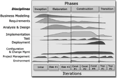
The Rational Unified Process (RUP) showed in Figure 1 does not specify a document that allows a formal tran-sition from the business modeling phase to the require-ments specification phase.When an intermediate informal document has not been defined, the specification of re-quirements is made in a highly subjective way, based only in the users. It causes it is not possible to establish a set of appropriated requirements to the business model.
∗E. S. Author is student of the School of Computer Science San Agustin University, Arequipa-Peru, Email: [email protected] †M. D. Author is student of the School of Computer Sci-ence San Agustin University, Arequipa-Peru, Email: [email protected]
[image:1.595.329.516.226.351.2]‡E. V. Author is docent of the School of Computer Science San Agustin University, Arequipa-Peru, Email: [email protected]
Figure 1: Development process RUP
The business processes describe the set of logically related tasks performed to achieve a defined business outcome in the company. They are characterized by been observable, measurable, improvement and repetitive [7]. It is by that reason that companies use them to reach most of their objectives.
The UML (Unified Modeling Language) notation is con-siderated as a standard of the software industry [8]. To represent business processes, UML proposes the Activity Diagram through which it is possible to have a signifi-cant set of requirements that could be transformed into a set of diagrams extremely important for the software construction [9].
To perform a transformation from a Processes Business Model to a Domain Model in a direct way without con-sider the interaction between an information object and an action of a activity diagram, only allows us to obtain classes without the association between them. Also, a point to consider is the specification of the information objects with the objective of obtaining a model of classes to which it is possible to add associations of generaliza-tion.
2
Related work
The transformation between models has called the atten-tion of many researchers. There are many articles on the subject, which perform transformations from a Business Process Model to a domain model and use cases, or only Domain Model. Barros [10] presents an article to obtain a class diagram. Garcia [11], introduced a strategy to obtain system model based on use cases and the domain model, from a business model implemented with UML activity diagrams. Rodriguez [12] presents a method of transformation between models using a set of rules de-fined with the QVT language (Query visual transforma-tion). In the work made by Estrada [13], he designs busi-ness models based on a goal oriented analysis and then obtains a model of software requirements.
3
Business processes modeling
and domain model
UML (Unified Modeling Language), is a graphic modeling language that is used to visualize, to specify, to construct and to document a software system [14]. It is endorsed by the OMG (Object Management Group) and has be-come the standard for modeling software applications, also is used to model other dominions, such as business processes.
In the following subsections we show the notation that al-lows to use UML for specifing the business process model and the domain model.
3.1
Business processes modeling
To model business processes with UML has its
advantages[15], such as: similar concepts, standard de-nomination, proven techniques and a short learning curve.
The methods and modeling techniques of business processes needs a standard denomination and UML pro-vides the activity diagram in order to model business processes, workflow and complex algorithms. In addi-tion, it makes possible to make a continuous traceability of the requirements to the implementation of code.
A UML activity diagram gives a broad notation to show the activity secuences, between them the parallel activ-ities. Larman [16] says: the activity diagrams could be applied to any perspective or purpose, but they are pop-ular to visualize the business processes and workflow in a organizational context.
In addition, Larman [16] affirms that these diagrams are very adapted to model business processes. Similarly, the RUP development process uses activity diagrams for the same aim. The most important elements that compose an activity diagram are those that are in the Figure 2.
Swimlanes
Actions Branch
Fork Expansion Regions
Object
Activity Final Initial Node
<<object>>
Merge
Join
[image:2.595.304.536.99.189.2]Activity diagrams commonly contain
Figure 2: Notation activity diagram
3.2
Domain model
A domain model is a visual representation of classes or objects of the real world in an interest domain [17]. It is also known as: conceptual model, model of domain objects and model of analysis objects.
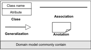
UML represents a domain model using class diagram, in which operations are not defined Figure 3, shows the el-ements that compose a domain model.
Clase Association
Generalization Anotation
Class name
Atribute
[image:2.595.339.499.361.449.2]Domainmodelcommonly contain
Figure 3: Notation domain model
4
Proposal of transformation
The transformation model we are proposing, consists of establishing a relationship between business modeling and requirements in the RUP development process, as shown in Figure 4. Additionally in Figure 4 we shown our proposal as it is integrated in a model driven archi-tecture. Thus we propose a methodology that is based on MDA and is applied to the RUP development process.
Our proposal of transformation is made up of the first stage, which performs the transformation from an activ-ity diagram to domain model, and a second stage in which it makes a refinement of the domain model obtained in the first stage.
Computation (CIM)
Independent Model
Computation Independent Platform (PIM)
P S
M (PSM)
latform pecific odel
Activity Diagram
Domain model
(Class Diagram) RequirementsAnalisys & Design
Implementation
MDA Our proposal RUP
Transformation Refinement
Business modeling
[image:2.595.316.525.676.757.2]To be able to better explain our proposal, we will present the case study [11] order registry, which is detailed as follows:
1. A customer submits an order, which has to include the order is date, the customer data and the desired products. A clerk of the sales department might also introduce the order requested by customer, placed by phone, or sent it by fax or ordinary mail to the sales department of the company.
2. The clerk checks the order (and completes it, if nec-essary), and begins its processing by sending it to the catalog manager, who is in charge of its analysis.
3. The catalog manager analyses the viability of each product of the order separately:
• if the ordered product is in the catalog,
manu-facturing is accepted.
• otherwise, it is considered as a special product,
and the catalog manager studies its manufac-turing:
– if it is viable, the manufacturing of the
spe-cial product is accepted;
– if it is not viable, the product is not going
to be manufactured.
4. Once the whole order has been studied, the catalog manager
• informs the sales department if every ordered
product is accepted or rejected.
• In the case that all the products of an order
have been accepted, a work order for every product is created, starting from a manufactur-ing template (the standard one, if the product was in the catalog, or a new one, specifically designed for the product, if it was not present in the catalog). Every work order is sent to the manufacturing manager, and its launching is considered pending.
5. The clerk informs the customer about the final result of the analysis of his or her order.
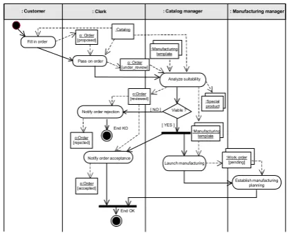
The Figure 5, shows the activity diagram proposed for this case of study.
In order to make the refinement processes it is necessary, to define the attributes of the information objects that compose the activity diagram. The following are the at-tributes defined for our case of study.
• Order: name, last name, address, date, telephone, product.
Fill in order
Pass on order
Notify order acceptance
End OK Notify order rejection
End KO
Analyze suitability
Viable ? [ NO ]
Launch manufacturing
[image:3.595.314.522.95.264.2]Establish manufacturing planning [ YES ]
: Manufacturing manager : Catalog manager
: Clerk : Customer
o: Order [proposed]
o:Order [rejected]
o:Order [accepted]
:Work order [pending] :Manufacturing
template :Catalog
:Special product o: Order
[under_review]
o:Order [reviewed]
:Manufacturing template
Figure 5: Case study register order
• Catalog: product, cost. stock. Special product:
name, type,description.
• Manufacturing template: product, feature.
• Order work: date, plant.
• Customer: name, last name. Clerk: name, last
name, zone.
• Catalog manager: name, last name, position.
• Manufacturing manager: name, last name, plant.
4.1
Transformation of the business process
model
The transformation is made initially identifying the infor-mation objects that composes the activity diagram. In our case of study, the information objects which could be immediately identifica as classes (to represent concepts of the business model) are: order, catalog, manufactur-ing template, special product, order work. The objects instanced several times but differ on their state, in the activity diagram, are considered as a single class. For instance, order has several states: proposed, evaluated, etc. but it represents the same information object.
The swimlanes, represent the role [14] inside the respon-sable organization for this activity. Similarly we consid-ered them like classes since they represent a concept of the business process model. For our case of study, is con-sidered as class, the swimlanes following: customer, clerk, catalog manager and manufacturing manager.
The form of obtaining of relations of association between the different extracted classes from the business model, is an important contribution of our proposal and differs from the previous works described in section 2.
Considering our previous premise, then it is possible to establish an action as tie between objects that enter and leave an action. We represent such action by means of a association relation between the classes that represent this information object.
[image:4.595.74.252.203.347.2] [image:4.595.315.524.429.527.2] [image:4.595.66.254.444.620.2]The discussed relationships are depicted in Figure 6.
[Order]
[Special product] Analyze suitability
a) Activity Diagram b) Domain model
Order
Special product
Figure 6: transformation activity diagram to domain model
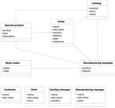
Finally, after applying the previously described criterion, the initial domain model is obtained ( Figure 7).
Order
+name +last name +product +address +date +telephone
Catalog
+product +price +stock
Manufacturing template
+product +feature
Special product
+product +type +description
Work orden
+plant +date
Customer
+name +last name
Clerk
+name +last name +zone
Catalog manager
+name +last name
+position +plant +name +last name
Manufacturing manager
Figure 7: Domain model after transformation
4.2
Refinement of the domain model
Business process model forms and other documents in an activity diagram are represented by the information objects.
Swimlanes being actors of the processes swimlanes, also has certain attributes, defined, such as permissions, po-sition and others. Thus, we obtain the classes with the attributes, from the documents of the business process model.
A refinement is required in order to obtain associations of generalization based in which a generic class contains a set of attributes that are common to all their specialized classes.
The generalization proposal, is inspired on the works of Silva [18] and Staudt [19]. In order to obtain general-ization associations the refinement process follows this criteria:
1. Compare the common attributes of the classes that have a association relation common.
2. If the number of attributes held in common is only one, then represents that attribute as a class and re-late it by means of a generalization association, with the classes that hold the same attribute they have in common. If the number of attributes is more than one, create a new class that contains those attributes in common.
3. For the classes which are resulted of the transforma-tion of a swimlanes, to use the same criterion used with the classes that have an association in common. This is because, swimlanes hold a common property: they being to the same activity diagram.
Special product
+type +description
Order
+feature
Catalog
+price +stock
Work orden
+plant +date +name +last name +address +date +telephone
Product
Customer
Clerk
+zone
User
+name +last name
+position
Catalog manager
+plant
Manufacturing manager Manufacturing template
Figure 8: Domain model after applying the refinement
In our case of study, a user class is created as a generaliza-tion of the classes: customer, commercial, technical head and production head. From the classes: order, manufac-turing template, catalog and special product; is extracted the product attribute that becomes part of a new class. As a final result of the refinement, the class diagram is obtained (Figure 8).
5
Conclusions and future works
model. Not being disturbed by the vision of the user or the engineer of requirements.
It is possible to consider, the actions of an activity di-agram as a source to trigger associations between the classes. In this way gives the class diagram a consistency since it represents of more accurately the business model way the activity diagram not losing of this form, the orig-inating information of the business model.
The specification of the structure of an information ob-ject, by the model of business processes, allows applying refinements to the class diagram in order to obtain gener-alization associations. As a future work, we would like to apply reverse engineer to the diagram of classes next to the diagram of cases of use, with the purpose of obtain-ing a model of business processes. And the use of QVT language to make the transformations.
References
[1] K. Weidenhaput, K. Pohl, M. Jarke, and P. Haumer., “Scenarios in system development: Current
prac-tice,” IEEE Software, March, 1998 and
In-ternational Requirements Engineering Conference (ICRE), 1998.
[2] I. Jacobson, M. Christerson, P. Jonsson, and
G. Overgaard, Objecto Oriented Software
Engineer-ing: A Use Case Driven Approach, 4th ed. Addison Wesley, 1993.
[3] G. Booch, J. Rumbaugh, and I. Jacobson,The
Uni-fied Modeling Language User Guide. Addison
Wes-ley, 1999.
[4] L. Antonelli and A. Oliveros, “Fuentes utilizadas por desarrolladores de software en argentina para
elici-tar requerimientos,” V Workshop on Requirements
Engineering, WER 2002, 2002.
[5] L. P. and V. Karakostas, System Requirements
En-gineering, M.-H. I. S. in Software Engineering, Ed. McGrawHill International Series in Software Engi-neering, 1995.
[6] D. Jitnah, H. J., and S. P., “Software requirements
engineering: An overview,” Technical Report
95-04, Peninsula School of Computing and Information Technology, Monash University, Melbourne, Aus-tralia, 1995.
[7] C. J. Quintana, “Indicadores de alineamiento entre procesos de negocios y sistemas informticos,” Mas-ter’s thesis, Universidad de Concepcin, 2002.
[8] A. Lonjon, “Business process modeling and stan-dardization,” 2004.
[9] P. Harmon, Business Process Trends, T. O. M. D.
Architecture and BPM, Eds. The OMG’s Model
Driven Architecture and BPM, 2005, vol. 2.
[10] J. P. Barros and L. Gomes, “From activity diagrams
to class diagrams,”International Conference on the
Unified Modeling Language, 2000.
[11] J. G. Molina, M. J. Ortn, B. Moros, J. Nicols, and A. Toval, “Towards use case and conceptual models
through business modeling,” International
Confer-ence on Conceptual Modeling, 2000.
[12] A. Rodrguez, E. Fernndez-Medina, and M. Piattini, “Hacia la obtencin de clases de anlisis y casos de uso
desde modelos de procesos de negocio,”Conferencia
Latinoamericana de Informtica (CLEI), 2007.
[13] A. Martnez, H. Estrada, and O. Pastor, “El modelo de negocios como origen de especificaciones de req-uisitos de software: una aproximacin metodolgica,” 2000.
[14] G. Booch, J. Rumbaugh, and I. Jacobson,The
Uni-fied Modeling Language User Guide Second Edition. Addison Wesley Professional, May 19, 2005.
[15] H.-E. Eriksson and M. Penker, Business Modeling
with UML: Business Patterns at Work. John Wiley
& Sons, 2000.
[16] G. Larman,Applying UML and patterns: An
intro-duction to object-oriented analysis and design and it-erative development. Westford, MA: Courier., 2005.
[17] J. Martin and J. Odell,Object-Oriented Methods: A
Foundation. Englewood (Miffs,NJ.: Prentice-Hall.), 1995.
[18] J. Silva, I. Ramos, and J. A. Cars´ı, “An algorithm
to compare ooconceptual schemas,” in ICSM, 2002,
pp. 351–358.
[19] B. S. Lerner, “A model for compound type changes
encountered in schema evolution,” ACM