Computer Aided Kinematic and Dynamic Analysis of
Cam and Follower
Prof. H.D.Desai
Prof. V.K.Patel
Abstract: Cam and follower are widely used in regulating,
opening and closing of valves (inlet and exhaust) in the internal combustion engines. Proper design of cam and follower is required for perfect tuning between opening and closing of valves with cam shaft speed. In this paper, the complete kinematic and dynamic analysis of cam and follower is done and critical angular speed is determined for each design to predict when the follower jumps off the cam. Analytical method is used, as it is more accurate and less time consuming and if programmed for the complete solution. The dynamic force analysis determines the cam contact forces and values of kinematic parameters at which the design fails. The analytical calculation is done in excel sheet for both kinematic and dynamic analysis of cam follower system for any rotational speed and angle of rise.
Keywords— Analytical Model, Cam–Follower, Constant
Velocity Motion, Cycloid Motion, Parabolic Motion, SHM.
I.INTRODUCTION
Cams are commonly used in opening and closing of valves in internal combustion engines. Both the inlet and outlet valves are regulated using cam and follower. The study of cam and follower mechanism becomes important for desired and required performance of the engines. In this paper, complete kinematic and dynamic analysis of cam and follower mechanism is carried out using analytical method. The equations for governing motion of the follower have been taken from the literature.[3]
The kinematic analysis of mechanism helps in answering many questions related to motion of the follower. In this present work displacement, velocity and acceleration values are calculated at each 100 rotation of cam using analytical relations. Fig.1 shows cam follower assembly.
Prof. H.D.Desai is with the Sardar Vallabhbhai National Institute of Technology, Surat, Gujarat, INDIA. phone:+919924900778; fax:+912612227334; e-mail: [email protected]).
Prof. V.K.Patelis is with the Sardar Vallabhbhai National Institute of Technology, Surat, Gujarat, INDIA. phone:+919879199149; fax:+912612227334; e-mail: [email protected]).
Fig.1: Cam follower assembly
The dynamic analysis includes the static and inertia force analysis of the follower. For normal working of mechanism, the resultant vertical force has to be in downward direction. If the instant force changes its direction, lifting of follower will take place and design will fail. In this paper kinematic parameters and forces are calculated analytically and critical angular speed of rotation is found for the design specification. The equations have been programmed for the computer solution for rotation of cam by an interval of 100.
II.KINEMATIC ANALYSIS
Equations for various governing motions of follower [2]:-
1. Cycloidal Motion
y
h
[( / ) (1/ 2 ) sin(2
/ )]
(1)2. Simple Harmonic Motion:-
y
(
h
/
2
)
[
1
cos(
/
)]
(2)3. Constant Velocity:-
y
h
/
(3)4. Constant Acceleration and Retardation: -
y
2
h
( / ) ,
2for
( / 2)
(4)
[
1
2
{
1
(
/
)}
]
2
h
y
,for
(
/
2
)
(5)
Where,
h
= Lift of the follower,= Angular displacement of cam, = Angle of rise,
y
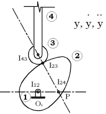
= vertical displacement of fillower. [image:2.595.73.258.504.702.2]Kinematic analysis of mechanism helps in determining the cam torque or torque delivered to the rotating cam. Using instantaneous centre of rotation of link 2 and link 4 we get torque delivered to the cam.
Fig. 2: Instantaneous centres of the cam.
Now we have,
2 2
p
v
y
O P
(6)2
( /
2)
O P
y
(7)P
O
F
T
2
32Y
2 (8)32
(
)
Y
s
F
P
F
m y
(9)Where,
y
= Velocity of follower,
y
= Acceleration of the follower,
2 = Angular Velocity of Cam, T2 = Torque delivered to the cam,F32 = Reaction of link 3 on link2,
m = Mass of follower, Fs = Spring force,
P = Force due to load.
For finding F32, dynamic analysis is done. Using the
equations of displacement, values of all kinematic parameters are calculated with the help of computer program.
III.DYNAMIC ANALYSIS
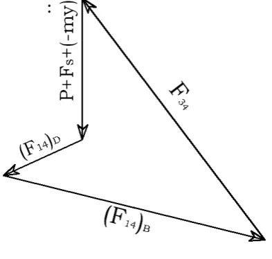
The resultant force acting on the follower, link 4 consists of the following forces:-
i. Reaction due to link3 on link4, F34,
ii. Reactions at support due to link1 on link4, (F14)B and (F14)D
iii. Inertia force due to mass of follower, (-my
),
iv. Spring force, Fs, v. Force due to load, P.
[image:3.595.54.275.122.274.2]Free body diagrams of link2, 3 and 4 are shown in Fig.3
Fig.3: Free body diagrams of Cam, Roller & Follower
Fig. 4: Force Polygon of forces acting on link 4
IV.RESULT AND DISCUSSIONS
The results computed from the program developed for kinematic and dynamic analysis of the follower are given for each 100 rotation of cam.
The results of kinematic analysis of the follower gives values of displacement, velocity and acceleration at different instants, which is shown in table: I, for simple harmonic motion,
Considering h = 0.018m, w2 = 62.83 rad/sec,
m = 1.6 kg, and = 1500.
Similar calculations may be done when motion of follower is constant velocity, parabolic and cycloidal.
The result from dynamic analysis gives the resultant vertical force on the follower and torque delivered to cam. Table: II shows Inertia Force, Spring Force, Resultant Force and torque according to cam rotation angle for simple harmonic motion.
[image:3.595.62.259.323.510.2]The variation of velocity and acceleration is shown in Fig.5. Similarly the variation of different forces with respect to cam angle is shown in Fig.6.
The knowledge of resultant force decides the critical angular velocity of the cam which is essential for the design of the cam mechanism.
Table: I: Displacement, Velocity and Acceleration of Follower according to Cam Rotation Angle.
Angle of Rotation of
Cam
Displacement of Follower
Velocity of Follower
Acceleration of Follower
m m/s m/s2
[
] [y
] [y
] [y
]0 0 0 51.16403
10 0.00020 0.14109 50.04597
20 0.00078 0.27600 46.74067
30 0.00172 0.39886 41.39257
40 0.00298 0.50429 34.23542
50 0.00450 0.58767 25.58201
60 0.00622 0.64537 15.81055
70 0.00806 0.67487 5.34810
80 0.00994 0.67487 -5.34810
90 0.01178 0.64537 -15.81055
100 0.01350 0.58767 -25.58201
110 0.01502 0.50429 -34.23542
120 0.01628 0.39886 -41.39257
130 0.01722 0.27600 -46.74067
140 0.01780 0.14109 -50.04597
[image:3.595.298.561.343.721.2]Table: II : Inertia Force, Spring Force, Resultant Force and torque according to Cam Rotation Angle.
Angle of Rotation of Cam
Inertia
Force Spring Force Resultant Force Torque
[θ] [N] [N] [N] [Nm]
0 -81.86245 0 -69.96245 0 10 -80.07356 0.27534 -67.89822 0.00286 20 -74.78507 1.08933 -61.79574 0.00598 30 -66.22811 2.40639 -51.92172 0.00951 40 -54.77667 4.16895 -38.70771 0.01351 50 -40.93122 6.30000 -22.73122 0.01783 60 -25.29689 8.70639 -4.69050 0.02216 70 -8.55696 11.28294 14.62599 0.02608 80 8.55696 13.91706 34.37401 0.02904 90 25.29689 16.49361 53.69050 0.03054 100 40.93122 18.90000 71.73122 0.03017 110 54.77667 21.03105 87.70771 0.02768 120 66.22811 22.79361 100.92172 0.02306 130 74.78507 24.11067 110.79574 0.01657 140 80.07356 24.92466 116.89822 0.00866 150 81.86245 25.20000 118.96245 0.00000
(A)
(B)
(C)
Fig.5: (A) Displacement, (B) Velocity and (C) Acceleration of follower according to Cam rotation Angle.
(A)
(B)
(D)
Fig.6 : (A)Inertia Force, (B) Spring Force, (C)Resultant Force on follower and (D) Torque Variation on cam according to Cam rotation Angle.
REFERENCES:
[1] Teodorescu,M. Kushwaha, M., Rahnejat, H. and Taraza, D. Elastohydrodynamic transient analysis of a four cylinder valve train system with flexibility. Proc./MechE, Part K:J.Multi-body Dynamics, 2005,219,13-25
[2] Rattan S.S., 2003, “Theory of Machines” Tata McGraw Hill, New York.
[3] Shigley, Joseph Edward, 2003, “Theory of Machines and Mechanisms” Tata McGraw Hill, New York [4] Norton, R.L., 2002, “Cam Design Manufacturing
Handbook”, Industrial Press Inc, SBN 0831131225. [5] Kushwaha,M., Rahnejat, H.Z.M. and Johns, P.M.,
Tribo-multibody dynamics analysis of valve train system. In proceedings of IMechE conference on multy body Dynamics: New Techniques and Applications, London, December 1998, paper c/553, pp.83-101 (Mechanical Engineering Publication, London).
[6] Dresner, T.L., and barkan, P., 1995, “New Methods For The Dynamic Analysis Of Flexible Single Input and Multy Input Cam Follower Systems” American Socity of Mechanical Engineering , New York. [7] Mahyuddin, A.I., Mitha, A. and Bajaj, A.K. on
methods of evaluation of parametric stability and response of flexible cam-follower systems. In proceedings of 21st Biennial ASME Mechanisms Conference on Cams, Gears, Robot and Mechanism Design, DE-Vol.26, 1990, pp 1-9.
[8] Pisano,A.P. and Freudenstein,F. Experimental and analytical investigation of the dynamic response of a high-speed cam-follower system - part1: Experimental investigation. Trans. ASME, J.Mechanisms, Trans., and automn in Des., 1983, 105(4), 692-704.
[9] Pisano,A.P. Coulomb friction in high-speed cam systems. Ttrans. ASME, J. Mechanisms, Trans., and Automn in Des., 1984, 106(4), 470-474.
[10] Ardayfio,D. Dynamics of high speed cam mechanisms with damped flexible followers driven by flexible cam shafts. ASME paper 76-DET-63, 1976
[11] Koster, M.P. Effect of flexibility of driving shaft on the dinamic behaviour of a cam mechanism. Trans.ASME, J.Engng for Industry,1975,92(2), 595-602.
[12] Kwakernaak,H., Smith, J., 1968, “Minimum Vibration Cam profiles”, Journal of Mechanical Engineering Science, Vol.10, No.3, June, pp219-227.