ISSN Print: 2329-3322
DOI: 10.4236/jfcmv.2018.63012 Jun. 29, 2018 136 Journal of Flow Control, Measurement & Visualization
Visualization of High-Speed Impact of Projectile
in Granular Sheet with Destructive Collision of
Particles
Chihiro Masaki
1, Kojiro Suzuki
1*, Yasumasa Watanabe
21Department of Advanced Energy, Graduate School of Frontier Sciences, The University of Tokyo, Kashiwa, Japan 2Department of Aeronautics and Astronautics, Graduate School of Engineering, The University of Tokyo, Tokyo, Japan
Abstract
The impact and penetration of a projectile in a particle-laden space, which are expected to have frequently occurred during the formation of the solar system and will occur in the case of an impact probe for future planetary exploration, were experimentally simulated by using the ballistic range. A two-dimensional sheet made from small glass beads or emery powder was formed by the free-falling device through a long slit in the test chamber evacuated down to about 35 Pa. A polycarbonate projectile of a hemisphere-cylinder or sphere shape with the mass and diameter about 4 g and 25 mm, respectively, was launched at the velocity up to 430 m/s, and the phenomena were observed by the high-speed camera at 20,000 fps. From a series of images, the bow-shock-wave-like laterally facing U-shaped pattern over the projectile and the absence of particles in the trail behind it were clearly seen. At the impact of the particles on the projectile surface, fine grains were formed due to the destructive collision and injected outward from the projectile. The images ob-tained by different lighting methods including the laser light sheet were com-pared. The effects of the particle diameter, its material and the impact velocity were also investigated.
Keywords
Ballistic Range, Impact, Granular Flow, Collision, High-Speed Camera
1. Introduction
Impact in a particle-laden space in a vacuum is not an unusual event. For exam-ple, it is well known that the destruction and aggregation of objects at the impact played an important role during the formation of the solar system [1]. An artifi-How to cite this paper: Masaki, C., Suzuki,
K. and Watanabe, Y. (2018) Visualization of High-Speed Impact of Projectile in Gra-nular Sheet with Destructive Collision of Particles. Journal of Flow Control, Mea-surement & Visualization, 6, 136-151. https://doi.org/10.4236/jfcmv.2018.63012
Received: March 9, 2017 Accepted: April 18, 2018 Published: June 29, 2018
Copyright © 2018 by authors and Scientific Research Publishing Inc. This work is licensed under the Creative Commons Attribution International License (CC BY 4.0).
DOI: 10.4236/jfcmv.2018.63012 137 Journal of Flow Control, Measurement & Visualization cial impact is expected to reveal the interior structure of a celestial object at the lunar and planetary exploration. In HAYABUSA 2 mission conducted by the Japan Aerospace Exploration Agency (JAXA), the impactor is planned to hit the surface of the asteroid Ryugu [2] for the in-situ observation of its interior struc-ture. To reveal the mechanism of the phenomena in such cases, the fundamental understanding about the impact in a particle-laden space is essential.
When the particles are packed in the space, the dynamics of their motions has been intensively and extensively investigated in the field of the terra-dynamics. The numerical method using virtual particles called DEM (Discrete Element Method) [1] [3] is known to appropriately simulate the behavior of the granular material both microscopically and meso-scopically. From a macroscopic view-point, the fluid-dynamics-like model is expected to work well. For example, the compressible and non-expanding fluid model successfully describes the nature of irreversible compression of granular materials [4].
When the particles at the undisturbed state are separately located at some dis-tance, the situation seems similar to the rarefied gas dynamics with relatively large mean free path. In the presence of the atmosphere, various studies have been numerically and experimentally conducted in the framework of the two-phase flow. For example, the combination of the Eulerian description of the dynamics of the fluid and the Lagrangian description of the motion of the float-ing solid particles is known to reasonably simulate the dusty flow around a body at a supersonic speed [5]. The phenomena around a circular cylinder in the stream of small spheres rolling down the slope of an inclined flat plate were ex-perimentally observed, assuming that the aerodynamic force acting on the par-ticles is negligible in comparison with the force due to collisions [6]. In most of the studies made so far, the destructive collision, which may frequently occur at the high-speed impact, was not taken into account. Considering the application to the planetary science or planetary exploration engineering mentioned above, the impact velocity is expected to be high, and the fundamental understanding about the phenomena involving the destructive collision into finer grains is ne-cessary based on the experimental study in the absence of the atmosphere.
DOI: 10.4236/jfcmv.2018.63012 138 Journal of Flow Control, Measurement & Visualization Figure 1. Schematic view of experimental setup.
The major objectives in the present study are 1) to reveal the characteristic features of the granular flow around a projectile penetrating on the sheet of par-ticles, 2) to clarify the presence of the destructive collision of particles at the projectile surface and its role in the granular flow field, and 3) to investigate the effect of the impact velocity, the diameter and the material of particles.
2. Method of Experiment
2.1. Ballistic Range and Particle Sheet Generator
DOI: 10.4236/jfcmv.2018.63012 139 Journal of Flow Control, Measurement & Visualization Figure 2. Photos of ballistic range facility and test chamber interior.
Figure 3.Snapshot of particle sheet before impact of a sphere model with exposure time 1 μs.
projectile was launched and penetrating on the particle sheet in this period. The projectile was finally caught in a semi-hard-landing manner by the projectile catcher made from the sponge layer and the oil clay.
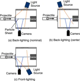
[image:4.595.242.506.364.538.2]DOI: 10.4236/jfcmv.2018.63012 140 Journal of Flow Control, Measurement & Visualization Figure 4. Arrangement of lighting and viewing area of camera (top view of test chamber).
image. After the penetration proceeded for some distance, the granular flow field around a projectile is expected to be in a steady state. The arrangement (b) was used for the observation after long penetration. We have to be careful to judge the presence of matter from a visualized image, because the dark image can be produced by not only the absence of matter but also the absence of light. To re-duce the risk of misunderstanding, the arrangement (c) with the front-lighting was tested and compared with the arrangement (a). For the lighting, the high-intensity metal halide lamp MID-25 FC (Lighterrace Inc.) with the maxi-mum power 250 W was used. To capture the images of the impact phenomena, the high-speed monochrome camera Phantom Miro 310 (Nobby Tech. Ltd.) was used. The sensitivity is 12 bit. The frame rate, exposure time and the spatial res-olution were set to be 20,000 fps, 1 μs and 512 by 256 pixels, respectively, in the present experiment.
2.2. Particles and Projectiles
DOI: 10.4236/jfcmv.2018.63012 141 Journal of Flow Control, Measurement & Visualization and iron oxide and is harder than the glass beads. The difference in the hardness of the particle is expected to change the nature of the destructive collision at the projectile surface and to affect the behavior of the granular flow around a body. In the case of type #40 glass beads, the number density of the particles was esti-mated as 5 × 10⁸ 1/m3 from the mass flow rate through the slit [7]. The falling
speed of the particles was estimated as about 3 m/s from two continuous snap-shots and the frame rate [7]. It was negligible in comparison with the flight ve-locity of the projectile.
Two types of the projectile shapes were tested, that is, the hemisphere cylinder and the sphere, as shown in Figure 5. Both types of the projectiles were made from the polycarbonate for its strength and low mass. The diameter of the body was 25.75 mm, which is the same as the inner diameter of the acceleration tube. Consequently, the projectile was launched without the sabot by the ballistic range. Such launch method without the sabot enables us to avoid significant disturbance added to the trajectory and attitude of the projectile at the sabot se-paration [9]. To obtain a high velocity from the ballistic range, the projectile mass was reduced by the hollow structure with the thickness 2 mm. The average mass of the hemisphere cylinder model and the spherical model is about 3.9 g and 4.3 g, respectively.
2.3. Uncertainty and Repeatability of Experimental Results
The projectile velocity was estimated from the frame rate and the difference in the projectile position between two continuous snapshots. The uncertainty in the estimated velocity was mainly caused by the blur of the projectile image in the exposure time [9], and it was less than 5%.
[image:6.595.270.475.539.701.2]Thanks to the launching of the projectile without the sabot, the uncertainty in the flight condition was relatively small. The free flight of the projectile before reaching the edge of the particle sheet was stable. The fluctuation in the velocity and the path angle during the free flight was smaller than ±10 m/s and ±1.5 de-grees, respectively [7]. The repeatability of the particle sheet generator was good
DOI: 10.4236/jfcmv.2018.63012 142 Journal of Flow Control, Measurement & Visualization because of its simple mechanism of the free falling. The variation in initial pres-sure at the test chamber was smaller than 1 Pa. The test chamber was carefully cleaned before each shot, because the presence of the residual particles and fine grains may affect the experimental pictures and becomes the serious source of the uncertainty. In the present study, qualitatively the same pictures were ob-tained in the same experimental condition and the same arrangement of the light source and the camera.
3. Results and Discussion
3.1. Two-Dimensionality of Phenomena
The present experimental setup was designed under the assumption that the motion of the particles mainly occurs on the plane of the particle sheet, because the plane of symmetry of a projectile coincides with that of the sheet. To confirm that, the setup of the lighting and the camera shown in Figure 6(a) was addi-tionally tested. Thanks to the mirror put in front of the projectile catcher, the oblique frontal view of the projectile was obtained. Figure 6(b) shows the sphere model just after the impact at the edge of the sheet of the glass beads #40. It is clearly seen that the particles in the sheet collided with the projectile surface on the plane of symmetry. At 0.1 ms after Figure 6(b), the projectile seems to move from the far side to the near side in the picture and to be hidden by the cloud of fine grains as shown in Figure 6(c). For clearness of the image, Figure 6(b) and
Figure 6(c) were intensified by enhancing the brightness and contrast by 20% using the image processing function of Microsoft Power Point 2008 for Mac.
The cloud seems to expand more in the vertical direction than in the horizontal direction. These pictures imply that the granular motion on the particles sheet was more significant than the out-of-plane motion. The fine grains were pro-duced by the destructive collision of the particle sheet at the projectile surface. Though the flight velocity cannot be estimated from the oblique view, it was ex-pected to be about 370 - 380 m/s from the experimental data of the spherical projectile at the same pressure of 0.6 MPa charged at the breech of the ballistic range.
To check the two-dimensionality of the phenomena, the visualization using the laser light sheet was also conducted. Two types of the laser light sheets, that is, the horizontal sheet and the vertical sheet, were tested as shown in Figure 7(a) and Figure 7(b), respectively. For the light source, Kentech model LDB2W blue laser was used. The maximum power, the wave length and the width of the laser sheet were 2 W, 450 nm and 2 - 3 mm, respectively. If the granular flow around the projectile had a significant three-dimensional out-of-plane structure, the laser light sheet would be scattered by the presence of the thick cloud of the particles and fine grains, and the cross section curve of the projectile surface could not be visualized by the laser light sheet. Figure 8(a) and Figure 8(b)
DOI: 10.4236/jfcmv.2018.63012 143 Journal of Flow Control, Measurement & Visualization (a)
(b)
[image:8.595.249.500.73.685.2](c)
DOI: 10.4236/jfcmv.2018.63012 144 Journal of Flow Control, Measurement & Visualization (a) (b)
Figure 7. Setup of laser light sheet. (a) Horizontal sheet; (b) Vertical sheet.
(a)
(b)
Figure 8. Snapshots of a sphere model moving from left to right in particle sheet with la-ser light sheet. (a) Horizontal lala-ser light sheet; (b) Vertical lala-ser light sheet.
contrast. In both pictures, the projectile moved from left to right, and the cross section curve of the projectile surface was clearly seen. Though the projectile ve-locity could not be estimated because of unclear images, it was expected to be about 400 m/s from the experiments in the similar condition. This fact indicated that the out-of-plane granular flow was not so significant to fully cover the pro-jectile surface.
[image:9.595.251.496.258.542.2]DOI: 10.4236/jfcmv.2018.63012 145 Journal of Flow Control, Measurement & Visualization
3.2. Formation of Granular Flow Field around a Projectile
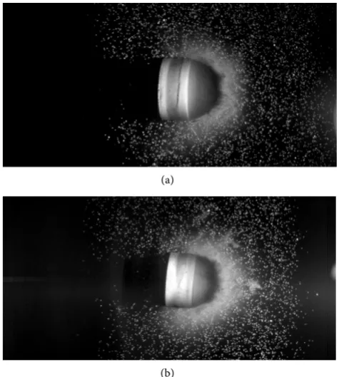
The typical pattern of a snapshot taken by the back-lighting arrangement (a) in
Figure 4 is shown in Figure 9(a). The particle sheet was made from the grass beads #40. The hemisphere cylinder model was used for the projectile, moving from left to right in the picture. The projectile velocity was estimated as 436 m/s. The snapshot was taken at 0.2 ms after the impact at the edge of the particle sheet. The bow-shock-wave-like laterally facing U-shaped structure over the projectile and the dark zone in its trail are clearly seen. The motion of the par-ticles in the other area seems undisturbed in the picture. The dark zone behind the body indicates the absence of the particles due to the sweeping effect of the
(a)
(b)
[image:10.595.245.505.239.677.2](c)
DOI: 10.4236/jfcmv.2018.63012 146 Journal of Flow Control, Measurement & Visualization projectile. The hazy pattern of the bow-shock-wave-like structure implies that this zone was composed of much finer grains than the glass beads. Such fine grains are expected to be produced by the destructive collision of the glass beads at the projectile surface. The fine grains spread away from the body and formed the laterally facing U-shaped structure as seen in Figure 9(a). It should be noted that such laterally facing U-shaped pattern was composed of two layers: the bright zone and the dark zone behind it. The presence of the dark zone may seem to indicate the absence of gains due to the blown-off effect by the grains re-flected at the body surface. However, in the front lighting picture under the al-most the same condition with the camera and lighting arrangement (c) in Figure 4, the dark zone in the back-lighting picture was captured as the hazy bright zone in the front-lighting picture as shown in Figure 9(b). One of the reasonable explanations for this discrepancy may be the assumption that the front surface of the projectile was covered with the thick cloud of the fine grains, which scattered and blocked the back light, resulting in the presence of the dark zone due to in-sufficient lighting. For clearness of the image, it was intensified by 50% and 67% in the brightness and contrast, respectively, from its original image shown in
Figure 9(c). Further investigations including the sampling of the fine grains are necessary to understand the mechanism for the images by the back-lighting and front-lighting to have significant difference.
[image:11.595.212.536.445.692.2]The image of the granular flow field around the projectile varies with the time from the impact at the edge of the particle sheet. Figure 10 shows a series of the snapshots after relatively long penetration. The images were intensified by 20% in the brightness and contrast. The sphere model and the glass beads #80 were
DOI: 10.4236/jfcmv.2018.63012 147 Journal of Flow Control, Measurement & Visualization used for the projectile and the particle sheet, respectively. The velocity was esti-mated as about 380 m/s from the snapshots. The images were taken by the cam-era and lighting arrangement (b) in Figure 4. The interval between the snap-shots is 0.05 ms. In this case, the highlight was obtained around the center of the picture. The light intensity gradually decreased and the image becomes darker with the distance from the highlight. From the snapshots 1, 2 and 3, the laterally facing U-shaped fine grain zone seems to move at almost the same speed as the projectile. Considering that the motion of the glass beads was not disturbed in front of this hazy laterally facing U-shaped zone, this pattern is expected to be formed by the mechanism similar to the shock wave in the compressible flow. In the wake side of the body, the brightness of the hazy image changes with the distance from the projectile. It may be possibly caused by the diffusion effect of the fine grains, which can penetrate into the zone of absence of the particles or fine grains in the trail of the projectile. It should be noted that the residual air existed in the test chamber due to the initial pressure before the shot and the in-flow from the acceleration tube during the shot. From the images of the particle sheet in the undisturbed zone, the motion of the glass beads due to the aerody-namic force from the flow of the residual air seems negligible. However, the mo-tion of the fine grains is much more easily influenced by the flow of the ambient air even in the low pressure environment. The diffusion of the fine grains behind the projectile seen in Figure 10 may be possibly caused in part by the presence of the wake flow of the residual air. The pattern around the projectile in the snapshot 6 seems almost the same as that in the snapshot 5. The granular flow field around the projectile seems to reach the steady state at the snapshot 6.
Consequently, the change in the pattern of the above pictures can be ex-plained by the destructive collision of the glass beads into fine grains at the pro-jectile surface, the removal of the particles or fine grains behind the propro-jectile by the sweeping effect, the shock-wave-like propagation of the laterally facing U-shaped zone of the fine grains in front of the projectile, and the diffusion of the fine grains into the trail of the projectile.
The above features were commonly observed in both cases of the sphere mod-el and the hemisphere cylinder modmod-el. However, the diffusion of the fine grains into the trail was much weaker in the case of the hemisphere cylinder model as shown in Figure 9. This was expected to be caused by the presence of the sharp corner at the rear end of the body as pointed out in [8].
3.3. Effect of Particle Size, Material and Impact Velocity
DOI: 10.4236/jfcmv.2018.63012 148 Journal of Flow Control, Measurement & Visualization Figure 11. Effect of particle size on formation of granular flow field around a sphere model.
filled with the diffusive fine grains in the case of the sheet of coarser particles. This fact indicates that the properties of the fine grains produced from the glass beads at the collision with the projectile surface depend on the initial particle size.
The effect of the material of the particle sheet on the granular flow field around a hemisphere cylinder model is shown in Figure 12, where the images taken at 0.15 ms after the impact with the sheet of the glass beads #40 and that of the emery powder are compared. The images were intensified by 20% in the brightness and contrast. The impact velocity is almost the same for both cases at about 440 m/s. The formation of the laterally facing U-shaped fine grain zone and the zone of absence of the particles or fine grains behind projectile was clearly seen in both cases. The dark zone in the laterally facing U-shaped struc-ture becomes narrower for the emery powder than for the glass beads. This fact indicates that the properties of the fine grains formed at the particle collision at the projectile surface also depend on the particle material.
DOI: 10.4236/jfcmv.2018.63012 149 Journal of Flow Control, Measurement & Visualization (a)
[image:14.595.261.487.66.336.2](b)
Figure 12. Effect of particle material on formation of granular flow field around a he-misphere cylinder model. (a) Glass beads #40; (b) Emery powder.
(a)
(b)
Figure 13. Effect of impact velocity on formation of granular flow field around a hemis-phere cylinder model.(a) 330 m/s; (b) 410 m/s.
[image:14.595.255.493.382.647.2]fac-DOI: 10.4236/jfcmv.2018.63012 150 Journal of Flow Control, Measurement & Visualization ing U-shaped layer of the fine grains was seen in front of the projectile than at the velocity 330 m/s. In addition, the luminous zone of the fine grain layer in front of the projectile becomes wider in the case of higher impact velocity. The mass flux of the colliding glass beads increases with the impact velocity and the destruction of the colliding glass beads becomes more significant at higher im-pact velocity. The velocity of the fine grains injected in the forward direction at the projectile surface is expected to increase with the impact velocity. As a result, higher production rate and higher injection velocity of the fine grains are ob-tained at higher impact velocity. Consequently, the zone of the fine grains spreads more quickly in front of the projectile at higher velocity.
4. Conclusions
The impact and penetration of a projectile in a particle-laden space were expe-rimentally investigated by using the ballistic range. A thin sheet made from small glass particles or emery powder was formed by the free-falling device through a long slit over the trajectory of a projectile in the test chamber. A poly-carbonate projectile of a hemisphere cylinder or sphere shape with the mass and diameter about 4 g and 25 mm, respectively, was launched at the velocity from 310 m/s to 430 m/s. The phenomena were observed by the high-speed camera at 20,000 fps. To reduce the effect of the flow of the residual air in the test chamber, it was evacuated beforehand. From the obtained images using various lighting and camera arrangement including the laser light sheet, the two-dimensionality of the phenomena was discussed. The bow-shock-wave-like laterally facing U-shaped pattern in front of the projectile and the zone of absence of the par-ticles or fine grains in the trail behind it were clearly observed in the pictures. The process of the formation of the granular flow field around a projectile was characterized by the destructive collision of the glass beads into fine grains at the projectile surface, the removal of the particles or fine grains behind the projectile by the sweeping effect, the shock-wave-like propagation of the laterally facing U-shaped zone of the fine grains in front of the projectile, and the diffusion of the fine grains into the trail of the projectile. The similar pattern was observed irrespectively to the projectile velocity, the size and material of the particles. However, the production rate and the spread speed of the fine grains depend on these conditions.
The above results suggest that the present phenomena can be numerically si-mulated by the model including the appropriate description for the motion of the original particles, the formation of the fine grains at the projectile surface and the flow of the fine grains. The numerical analysis using such model is ex-pected to be quite useful for understanding of the formation of the celestial ob-jects in the solar system, designing the impact probe for planetary exploration in the future and so on.
Acknowledgements
DOI: 10.4236/jfcmv.2018.63012 151 Journal of Flow Control, Measurement & Visualization 16H04585 of Japan Society for the Promotion of Science.
References
[1] Wada, K., Senshu, H. and Matsui, T. (2006) Numerical Simulation of Impact Cra-tering on Granular Material. Icarus, 180, 528-545.
https://doi.org/10.1016/j.icarus.2005.10.002
[2] Saiki, T., Imamura, H., Sawada, H., Arakawa, M., Kadono, T., Takagi, Y. and Wada, K. (2013) Small Carry-On Impactor of Hayabusa2 and Its Impact Operation. Web Paper Archives of the 29th International Symposium on Space Technology and Science, Nagoya, 2-9 June 2013, 2013-d-18.
http://archive.ists.or.jp/upload_pdf/2013-d-18.pdf
[3] Nakamura, A.M., Setoh, M., Wada, K., Yamashita, Y. and Sangen, K. (2013) Impact and Intrusion Experiments on the Deceleration of Low-velocity Impactors by Small-body Regolith. Icarus, 223, 222-233.
http://dx.doi.org/10.1016/j.icarus.2012.11.038
[4] Suzuki, K. (2017) Numerical Simulation of High-Speed Impact on Regolith Using Compressible and Non-Expanding Fluid Model. Web Paper Archives of the 31st International Symposium on Space Technology and Science, Matsuyama-Ehime, 3-9 June 2017, 2017-k-47.http://archive.ists.or.jp/upload_pdf/2017-k-47.pdf
[5] Ishii, R., Hatta, N., Umeda, Y. and Yuhi, M. (1990) Supersonic Gas-Particle Two-Phase Flow around a Sphere, Journal of Fluid Mechanics, 221, 453-483.
https://doi.org/10.1017/S0022112090003639
[6] Yano, R. and Suzuki, K. (2012) Visualization of Granular Flow around Obstacle.
Visualization of Mechanical Processes, 2.
http://dx.doi.org/10.1615/VisMechProc.v1.i4.50
[7] Masaki, C. (2017) Ballistic Range Experiment of Sphere in Dusty Atmosphere. Web Paper Archives of the 31st International Symposium on Space Technology and Science, Matsuyama-Ehime, 3-9 June 2017, 2017-s-10-e.
http://archive.ists.or.jp/upload_pdf/2017-s-10-e.pdf
[8] Masaki, C., Watanabe, Y. and Suzuki, K. (2017) Visualization of Projectile Flying at High Speed in Dusty Atmosphere. IOP Conference Series: Materials Science and Engineering, Volume 249, conference 1,14th International Conference on Fluid Control, Measurements and Visualization (FLUCOME 2017), University of Notre Dame, 8-12 October 2017, 012015. https://doi.org/10.1088/1757-899X/249/1/012015