© 2019, IRJET | Impact Factor value: 7.34 | ISO 9001:2008 Certified Journal
| Page 185
RECKONING THE VEHICLE USING MATLAB
Ms. Shyamalaprasanna A
1, Ms. Dharshini J
2, Ms Brindha R
31
Assistant professor, Department of ECE, Bannari Amman Institute of Technology, Erode, Tamilnadu
2
UG Scholar, Department of ECE, Bannari Amman Institute of Technology, Erode, Tamilnadu
3
UG Scholar, Department of ECE, Bannari Amman Institute of Technology, Erode, Tamilnadu
---***---Abstract - Counting the wide variety of vehicles is an essential part of image processing. Knowing the variety of vehicles in the image can be useful for further evaluation in a huge variety of applications. In this venture we propose a simple technique for determining the wide variety of vehicle in an image. Existing strategies contain counting based totally on location of car, color of the vehicle, making use of part detection strategies etc. This mission work also goals at figuring out the right value of density by clearing the vehicle touching the borders of the image. In this challenge the usage of MATLAB with image processing toolbox the count and density values are calculated and estimating the proper count. Automatic detecting and monitoring vehicles in video surveillance records is a totally tough thing in computer vision with essential practical programs, along with traffic evaluation and security. Manually reviewing the large amount of facts they generate is frequently impractical. Thus, algorithms for reading video which require little or no human enter is a scientific answer. Video surveillance structures are focused on monitoring, moving vehicle classification and tracking. A car tracking and classification system is described as one that could categorize transferring vehicles and similarly classifies that into various categories. Traffic control and statistics structures rely mainly on sensors for estimating the visitors parameters.
Key Words: Image processing, Video surveillance, MATLAB, Algorithm, Automation.
1. INTRODUCTION
The increase in the vehicle count leads to many troubles by causing traffic in highways. As a result it causes accidents, congestion in traffic and other drastical problems which leads to tough transportation over highways. To solve every problems in traffic we should attentive over vehicles. In this case vehicle detection and counting is necessary to avoid those activities. Manual surveillance video of traffic is tough where result cannot be accurate and efficient. Automation in traffic surveillance is indeed here. The main objective and scope of this project is to detect and count vehicles by inserting a high quality traffic video. The following are the basic things to be done for the vehicle detection and counting. The video is monitored continuously for detection of vehicles. The video is segmented in frames and they are counted. This system also categorizes vehicles into different classes.
1.1 PROBLEM DEFINITION
Counting vehicles using magnetic loops are the current approaches for traffic control and monitoring. This approach uses temporal differencing method which has not complete extraction of the shape of the moving vehicle that leads to fail in counting. And also in feature based tracking and region based tracking methods there is a major drawback of blur extracted image and time consuming respectively. To overcome this problem background subtraction method is used.
1.2 OBJECTIVES
Detecting the moving vehicles in a highway video
Tracking the detected vehicles in video Counting number of vehicles in video
2. LITERATURE SURVEY:
1. Gupte S- Detection and Classification Vehicles (March, 2002) [1]. It gives algorithms for imaginative and prescient-primarily based detection and type of automobiles in monocular picture sequences of traffic scenes recorded by way of a desk boundcamera. Vehicles are modeled as rectangular patches with sure dynamic conduct. The proposed technique is primarily based on the established order of correspondences among regions and objects, as the objects circulate through the video series.
2. Toufiq P and Anurag Mittal,- A Framework for feature selection for Background subtraction (2006) [2].Background subtraction is a widely used tool for surveillance of traffic video, human and object motion analysis etc. This algorithm selects the useful images for framework to differentiate and to eliminate foreground objects from the background scene.
3. PROPOSED MODEL
[image:2.595.40.285.249.299.2]Fig 1 gives an outline of the moving vehicle identification in a video sequence. The framework utilizes a current video sequence and the first frame is taken as the reference frame for car detection. The other frames are considered as the input frames. The backgrounds are eliminated by comparing the input and output frames. In the event that a vehicle is available in the input frame it is continued. The vehicle detection is in this way tracked by different procedures, specifically, blob analysis method and background method.
Fig 1 Overview of vehicle detection and counting system
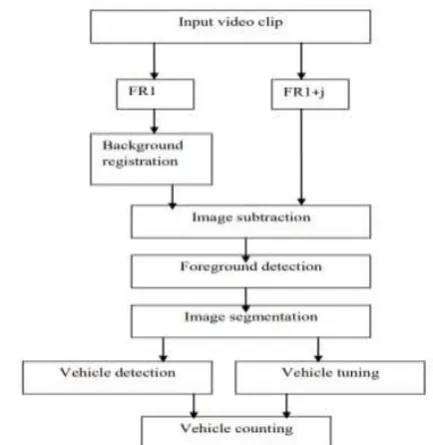
The first frame is considered as the background frame for video clips in adaptive background subtraction method. The architecture for the proposed model is explained in figure 3.1. The video clips obtained by background subtraction method is read and converted to frames. In first stage of the process, difference between the frames are generated (i.e FIR1, FIR1+j). In the second stage the difference obtained are generated and in the next stage the pixels that are having same values in the different frames are got eliminated.
The images that are obtained in the third stage are post processed in the fourth stage. Vehicle tuning and vehicle counting is done in the fifth stage. Finally counting is done in the last stage.
Fig 2 Architecture of vehicle detection and vehicle counting
3.1 BACKGROUND DETECTION:
Learned background detection method is used to extract the salient features from video clips in the general detection approach. This process involves in subtracting the images from background scenes. To determine the background image the first frame is considered as initial background and the resultant different images is threshold. The vehicle detection becomes very difficult when colour of the vehicle and the background becomes same or some parts of the vehicle are aged with the background. Due to this an error output is obtained.
3.2 FOREGROUND DETECTION:
An occlusion which is caused by errors and vehicle type can be rectified by detecting the information. After this the foreground dynamic vehicles are obtained by subtracting the background images from the video frames. Post processing technique is used to reduce the noise interference in the video.
3.3 IMAGE SEGMENTATION:
1. In the first step we have to segment the vehicle containing region and detect the unknown objects in the image.
2. In the second step suitable features and vehicles are extracted from the image. Data can be reduced by feature extraction process which affects the input pattern.
3. Final step is classification. Gray scale image is segmented by morphology operation through investigation.
3.4 VEHICLE TUNING:
There will be always some noise present in both the vehicle and background region due to irregular vehicle moment. Post processing technique is applied in foreground image to smoothen the vehicle boundaries. Binary image of the detected vehicle is the final output of the vehicle tuning process.
3.5 VEHICLE COUNTING:
[image:2.595.48.265.532.755.2]© 2019, IRJET | Impact Factor value: 7.34 | ISO 9001:2008 Certified Journal
| Page 187
VEHICLE COUNTING MODULE SPECIFICATIONS:
VEHICLE DETECTION:
Video analysis means detecting the moving vehicle. It can be used in various fields like people tracking, traffic monitoring and video surveillance. There are three different segmentation techniques, namely optical flow method, entropy mask and frame difference. The entire shape of the moving vehicle is not extracted well in frame difference method but it is good in implementation and computation.
Reference image and current frame is used by the adaptive background subtraction method. The difference between reference and current frame gives the threshold which is considered as moving vehicle. Moving vehicles can be detected even when the camera is moving by optical flow method but it is very sensitive to noise and need more time for its computational complexity. Since local computation is used in optical flow method the real image appears quite noisy. Hence optical flow method cannot be used to detect the moving vehicles.
3.6 VEHICLE TRACKING:
Vehicle tracking can be done by continuously identifying the vehicles present in the video sequences and boundaries around the vehicles. The most challenging problem is vehicle tracking. Vehicle tracking becomes more difficult due to camera motion, vehicle-to-scene and vehicle-to-vehicle occlusion, no rigid vehicle structures, changing vehicle pattern and abrupt vehicle motion. Vehicle tracking is usually done in high level applications that can be used to identify the exact location of the vehicle.
3.6.1 COLOR IDENTIFICATION:
Slandered color module can be used to identify the vehicle color with the help of intensity of threshold image. Color spaces can separate the illumination component and chromatic component. The idea of preserving computational cost and saving intensity components leads to RGB space.
[image:3.595.335.537.113.321.2]3.7 DATAFLOW DIAGRAM FOR VEHICLE DETECTION
Fig 3 Dataflow diagram for vehicle detection
As shown in the block diagram the read image is taken as the input image by converting it to frames. The converted frame is difference from background and foreground image. Image subtraction is used to detect the vehicle in the frame. Video analysis can be used to detect the moving vehicles in vehicle tracking system, traffic monitoring and surveillance.
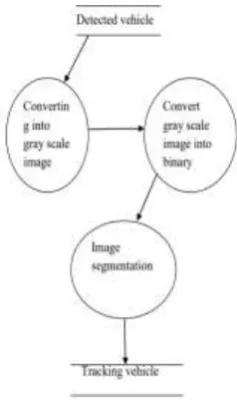
3.8 DATAFLOW DIAGRAM FOR VEHICLE TRACKING:
Fig 4 Dataflow diagram for vehicle tracking
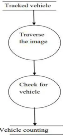
[image:3.595.357.476.465.670.2]3.9 DATAFLOW DIAGRAM FOR VEHICLE COUNTING:
Fig 5 Dataflow diagram for vehicle counting
The tracked binary image is considered as the input image for vehicle counting. To detect the presence of vehicle the binary image is scan from top to bottom. Two variables are kept to count the number of vehicle and information about the registered vehicles. When a new vehicle is detected in the frame it is first compared with the buffer to check whether the vehicle is already present in the previous frame or not. If it is not present the count is incremented else it is treated as the part of already existing image and the vehicle presence is eliminated. This is used to final counting of vehicle. Sometime two images are merged to a single image due to occlusion process.
4. ALGORITHEM AND OUTPUT
4.1 ALGORITHEMS:
Four major steps that involve in detecting the vehicles are explained above proposed model. In the first step the video clips is divided into number of frames. The second step involves in identifying background registered image and finding the frame difference. Finally in the last step post processing is done and background is eliminated thus maintain vehicle counting. The main aim of this algorithm is to count number of vehicles present in the given video. The given input video is divided into number of frames. Every individual frame is considered as an image. The obtained RGB image is converted to gray scale image. In the next step difference between the images is obtained. The interval between the frames is based on the speed of the video sequence. Some morphological operators are used to segment the vehicle edge counting and it is detected. The counts gest incremented once the vehicle got detected and in it is displayed in the command window.
[image:4.595.309.589.394.578.2]4.2 INPUT VIDEO SEQUENCE:
Fig 6 Input video sequence
This is the input video sequence given through an traffic video as input.It segments into frames where the first frame of the input video is considered as reference frame.
4.3 OUTPUT VIDEO FRAME:
Fig7 Output video sequence
With the help of reference frame the vehicle is detected by subtracting the background and it is outlined by a rectangular box to identify the vehicle which is to be counted.
5. CONCLUSION
© 2019, IRJET | Impact Factor value: 7.34 | ISO 9001:2008 Certified Journal
| Page 189
the exact counting and detection of vehicles of a live traffic in highways. With the help of some recognition techniques vehicles can be classified accordingly. This system is now designed for the counting and detection of vehicles and further this can be advanced for alarming systems during traffic in highways and also for identification of types of vehicles.
REFERENCES:
[1] Gupte S., Masoud O., Martin R. F. K. and Papanikolopoulos N. P.,―Detection and Classification of Vehicles‖, In IEEE Transactions on Intelligent Transportation Systems, vol. 3, no. 1, March, 2002,
[2] Toufiq P., Ahmed Egammal and Anurag Mittal, ―A Framework for Feature Selection for Background Subtraction‖, In Proceedings of IEEE Computer Society Conference on Computer Vision and Pattern Recognition(CVPR’06), 2006.
[3] N. Kanhere, S. Pundlik and S. Birchfield, ―Vehicle Segmentation and Tracking from a LowAngle Off-Axis Camera‖, In IEEE Conference on Computer Vision and Pattern Recognition‖, San Diego, June,2005.
[4] Deva R., David A., Forsyth and Andrew Z., ― Tracking People by Learning their Appearance‖, In IEEE Transactions on Pattern Analysis and Machine Intelligence,vol. 29, no1, Jan. 2007