International Journal of Emerging Technology and Advanced Engineering
Website: www.ijetae.com (ISSN 2250-2459, Volume 2, Issue 7, July 2012)226
Stability Improvement of Power System By Using SVC With
PID Controller
Habibur Rahman
1, Dr. Md. Fayzur Rahman
2, Harun-Or-rashid
31,3Department of Electrical and Electronic Engineering, Rajshahi University of Engineering & Technology
2Professor, Department of Electronics and Communication Engineering, Daffodil International University
Abstract— This paper presents the model of a static VAR compensator (SVC) which is controlled externally by a Proportional Integral Differential (PID) controller for the improvements of voltage stability and damping effect of an on line power system. The PID controller parameters has been selected by using Ziegler-Nichols tuning rule method. Both single phase and three phase faults have been considered in the research. Phasor simulation method has been used & Simulation result shows that the SVC with PID controller is more effective to enhance the voltage stability and increases power transmission capacity of a power system. It has been observed that the SVC ratings are only 40 MVA with PID and 200 MVA without PID. The damping was 0.01% with PID controller in compared to that of 0.5% without PID. For single line to ground fault, Using PID the system voltage, power(P,Q), speed deviation(dω) becomes stable in 1.5s and without PID controller 3.5s, 3s & 4.5s respectively. Similarly, For L-L faults, Using PID the system voltage, power(P,Q),speed deviation(dω) becomes stable in 1.4s, 0.7s & 2.2s and without PID controller system becomes stable in 5s respectively. So with PID controller the system performance is greatly enhanced.
Keywords—Static VAR Compansator (SVC), PID Controller, AVR, TCR, Voltage regulation, MATLAB Simulink.
I. INTRODUCTION
Power system stability improvements is very important for large scale system. The AC power transmission system has diverse limits, classified as static limits and dynamic limits[2 3].Traditionally, fixed or mechanically switched shunt and series capacitors, reactors and synchronous generators were being used to enhance same types of stability augmentation[2]. For many reasons desired performance was being unable to achieve effectively.
A static VAR compensator (SVC) is an electrical device for providing fast-acting reactive power compensation on high voltage transmission networks and it can contribute to improve the voltage profiles in the transient state and therefore, it can improve the qualities and performances of the electric services[3]. An SVC can be controlled externally by using properly designed different types of controllers which can improve voltage stability of a large scale power system. Authors also designed PI controller[6] and system performances were investigated. With a view to getting better performance PID controller has been designed for SVC to injects Vqref externally. The dynamic nature of the
SVC lies in the use of thyristor devices (e.g. GTO, IGCT)[4]. Therefore, thyristor based SVC with PID controllers have been used to improve the performance of multi-machine power system.
II.CONTROL CONCEPT OF SVC
An SVC is a controlled shunt susceptance(B) which inject reactive power (Qnet) into thereby increasing the bus
voltage back to its net desired voltage level. If bus voltage increases, the SVC will inject less (or TCR will absorb more) reactive power, and the result will be to achieve the desired bus voltage[Fig.1]. Here, +Qcap is a fixed
capacitance value, therefore the magnitude of reactive power injected into the system, Qnet, is controlled by the
magnitude of –Qind reactive power absorbed by the TCR.
International Journal of Emerging Technology and Advanced Engineering
Website: www.ijetae.com (ISSN 2250-2459, Volume 2, Issue 7, July 2012)227
Bus Bar C.B P.T Vsvc Isvc Reactor Thyristor Vulve SVC Controller AVR Inductive reactive power absorbtion (-Qind)Transformer TCR Pulse generator Capacitive reactive power injection
(+Qcap)
Qnet=Qcap - Qind
Fixced Capacitor
Fig.1 SVC based control system
III. SVCV-ICHARACTERISTICS
The SVC can be operated in two different modes:
a) In voltage regulation mode (the voltage is regulated within limits as explained below).
b) In VAR control mode (the SVC susceptance is kept constant).
From V-I curve of SVC, From Fig.2[2,3], V=Vref+Xs.I,: In regulation range(-Bcmax<B<Bcmax)
V=I/Bcmax, , : SVC is fully Capacitive(B=Bcmax)
V=1/Blmax, : SVC is fully inductive(B=Blmax)
Vref dv Blmax Bcmax Isvc-base Isvc
SVC operating point
Inductive(-)
Capacitive(+) 0
Xslope=dv/Isvc-base
v
Fig.2 Steady state(V-I) characteristic of a SVC
IV. PIDCONTROLLER TUNING PROCESS
The process of selecting the controller parameters to meet given performance specifications is called PID tuning. Most PID controllers are adjusted on-site, many different types of tuning rules have been proposed in the literature[1]. Using those tuning rules, delicate & fine tuning of PID controllers can be made on-site. Also automatic tuning methods have been developed and some of the PID controllers may possess on-line automatic tuning capabilities[1].
The PID controller has three term control signal[1],
...(1) In Laplace Form,
...(2)
Fig.3 Block diagram of PID controller parameters
For selecting the proper controller parameters, Ziegler-Nichols PID Tuning[1], Second Method is described below. In the 2nd method, the parameter is selected as Ti=∞,Td=0. Using the proportional controller action[Fig.4][1] only
increase Kp from 0 to a critical value Kcr. At which the
output first exhibits sustained oscillations[Fig.5].
Fig.4 PID controller is in proportional action
Fig.5 Determination of sustained oscillation (Pcr)[1]
Thus the critical gain Kcr & the corresponding period Pcr
are experimentally determined. Ziegler and Nichols suggested that the values of the parameters Kp Ti Td should
set according to the following formula.
Kp=0.6Kcr , Ti=0.5Pcr , Td=0.125Pcr
Notice that the PID controller tuned by the 2nd method of Ziegler-Nichols rules gives,
………..(3)
dt
t
de
T
K
dt
t
e
T
K
e(t)
K
t
u
p di p p
)
(
)
(
)
(
T
s
T
1
1
K
E(s)
U(s)
d i p
T
s
International Journal of Emerging Technology and Advanced Engineering
Website: www.ijetae.com (ISSN 2250-2459, Volume 2, Issue 7, July 2012)228
……(4)
( )
( )………...(5)
[image:3.612.49.282.244.313.2]
Thus the PID controller has a pole at the origin and double Zeros at S= - 4/Pcr [Fig.6].
Fig. 6 PID controller with tuning parameters
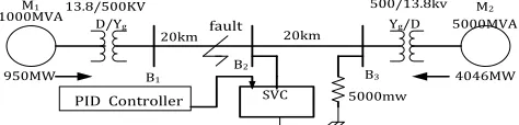
V.MODELLING OF POWER SYSTEM WITH SVC This example described in this section illustrates modelling of a simple transmission system containing 2- hydraulic power plants. SVC has been used to improve transient stability and power system oscillations damping. The phasor simulation method can be used. A single line diagram represents a simple 500 kV transmission system is shown in Fig.7(a).
M1 13.8/500KV D/Yg
950MW 1000MVA
20km 20km
SVC B1
B2
B3
500/13.8kv Yg/D
5000mw
M2
5000MVA
4046MW
PID Controller fault
Fig.7(a) Single line diagram of 2-machine power
A 1000 MW hydraulic generation plant (M1) is connected to a load centre through a long 500 kV, total 40km transmission line. A 5000 MW of resistive load is modelled as the load centre. The remote 1000 MVA plant and a local generation of 5000 MVA (plant M2) feed the load. A load flow has been performed on this system with plant M1 generating 950 MW so that plant M2 produces 4046 MW.
The line carries 944 MW which is close to its surge impedance loading (SIL = 977 MW).To maintain system stability after faults, the transmission line is shunt compensated at its centre by a 200 MVAR Static VAR Compensator (SVC).
The SVC does not have any controller unit. Machine & SVC parameters has been taken from ref.[7].The complete simulink model of this network is shown in fig.7(b). To maintain system stability after faults, the transmission line is shunt compensated at its centre by a 200 MVAR Static VAR Compensator (SVC). The two machines are equipped with a hydraulic turbine and governor (HTG) [Fig.8],excitation system, and power system stabilizer (PSS). Another machine is swing generator.PSS is used in the model to add damping to the rotor oscillations of the synchronous machine by controlling its excitation current[3]. Any disturbances that occur in power systems due to fault, can result in inducing electromechanical oscillations of the electrical generators. Such oscillating swings must be effectively damped to maintain the system stability and reduce the risk of stepping out of synchronism.
VI. SIMULATION RESULTS (WITHOUT PID) The load flow solution of the above system is calculated and the simulation results are shown below. Two types of faults: A. Single line to ground fault & B. L-L fault have been considered.
A.Single line to ground fault
Consider the fault occurred at 0.1s & circuit breaker is opened at 0.2s (4-cycle fault),Without SVC, the system voltage, power & machines oscillates goes on unstable[Fig.9(a-c-e)]. But if SVC(without PID) is applied then voltage becomes stable within 3s [Fig.9(b)],power becomes within 3s[Fig.9(d)] & machines oscillation becomes stable within 4.5s [Fig.9(f)]. The results has been summarized in table-I.
0
.
125
s
0.5P
1
1
K
6
.
0
)
(
crcr
cr
P
s
s
[image:3.612.52.289.433.490.2]International Journal of Emerging Technology and Advanced Engineering
Website: www.ijetae.com (ISSN 2250-2459, Volume 2, Issue 7, July 2012)229
Fig.7(b) Complete simulink model of 2-machine power system
Fig.8 PSS, HTG and excitation system block diagram for machine 1.
[image:4.612.71.546.143.293.2] [image:4.612.321.563.526.630.2] [image:4.612.47.293.526.638.2]International Journal of Emerging Technology and Advanced Engineering
Website: www.ijetae.com (ISSN 2250-2459, Volume 2, Issue 7, July 2012)230
Fig.9(c) Bus power,P in MW during fault (Without SVC)
Fig.9(d) Bus Power(P)in MW for 1-Ø faults(with SVC)
Fig.9(e) Speed deviation for 1- phase fault(without SVC)
Fig.9(f) Speed oscillations for 1- phase fault(with SVC)
B. Three Phase (Line-Line) fault
During 3-phase faults, If no SVC is applied then system voltage & machines speed deviations becomes unstable But when SVC(without PID) is applied then the system voltage becomes stable within 5s [Fig.10(a)] & machines speed deviation becomes stable within 5s [Fig.10(b)].
Fig.10(a) Bus Voltage(Va) in p.u for L-L phase fault
Fig.10(b) Machines speed deviation for L-L fault
VII. MODELLING OF PIDCONTROLLER FOR SVC The proposed PID controller parameters has been deigned by using Ziegler-Nichols tuning method [sec. IV]. The critical gain (Kcr) for which the plant output gives a
sustained oscillation[Fig.5] is determined for this network(Kcr=200) & corresponding period of Pcr [Fig.5] is
also determined from Fig.9(a) & found Pcr=0.2.Thus the
International Journal of Emerging Technology and Advanced Engineering
Website: www.ijetae.com (ISSN 2250-2459, Volume 2, Issue 7, July 2012)231
Fig.11(a) PID controller simulink model with dω input.
Fig.11(b) PID controlled SVC simulink model with dω input
Fig.11(c) PID controller simulink model with pm input.
Fig.11(d) PID controlled SVC simulink model with pm input
VIII.SIMULATION RESULT (WITH PID)
The network remains same [Fig.7],just simple SVC is replaced by PID controlled SVC[Fig.11(b,d)]. During fault, when the parameters speed deviation dω & mechanical power deviation, pm always monitored by PID controller & taking input of those oscillation, after processing as shown in fig.11(a,c).PID reduces damping of power system oscillation. Two types of faults has been considered: A. Single line to ground fault and B. three phase L-L fault.
A. Single line to ground fault
During 1-phase faults, if PID is used as SVC controller then, the system voltage becomes stable within 1.5s with 0% damping [Fig.12(a)] & Machines speed deviation becomes stable within 1.6s [Fig.12(d)] & Both power (P,Q) becomes stable within 1.6s [Fig.12(b-c)].
Fig.12(a) Bus voltage in p.u for 1-Ø fault (with PID)
Fig.12(b) Bus power,P in MW for 1-Ø fault (with PID)
Fig.12(c) Bus power,Q in MVAR for 1-Ø fault (with PID)
Fig.12(d) Machines speed deviation for 1-Ø fault(with PID)
dw 2
Vqref * 1
Transfer Fcn 1 s+20 s Transfer Fcn s+20 s Saturation Gain 471 .23 dw1 2 dw2 1 SVC Vr e f m
A B C
SVC PID Controller dw2 dw1 Vqref * dw dw 1 dw2 Bus Selector 8 7
6 <B (pu)>
<Vm (pu)>
pm 2
Vqref * 1
Transfer Fcn 1 s+20 s Transfer Fcn s+20 s Saturation Gain 471 .23 pm 1 2 pm 2 1 SVC Vr ef m
A B C
SVC PID Controller pm2 pm1 Vqref * pm pm 1 pm 2 Bus Selector 8 7 6 <B (pu)> <Vm (pu)>
0 0.2 0.4 0.6 0.8 1 1.2 1.4 1.6 0.4 0.6 0.8 1 1.2 1.4 1.6 time,t B u s V o lt a g e Va
0 0.5 1 1.5
0 500 1000 1500 2000 time,t B u s P o w e r
0 0.5 1 1.5
-500 0 500 1000 time,t R e a c ti v e P o w e r, Q
0 0.2 0.4 0.6 0.8 1 1.2 1.4 1.6 -4
-2 0 2 4x 10
International Journal of Emerging Technology and Advanced Engineering
Website: www.ijetae.com (ISSN 2250-2459, Volume 2, Issue 7, July 2012)232
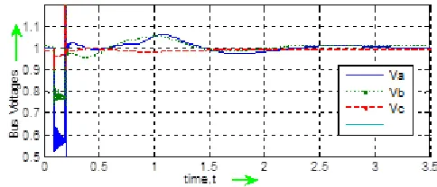
A.Three Phase (Line-Line) fault
During 1-phase faults, if PID is used as SVC controller then, the system voltage becomes stable within 1.4s with 0% damping [Fig.13(a)] & Machines speed deviation becomes stable within 2.2s [Fig.13(d)] & Both power (P,Q) becomes stable within 0.6s [Fig.13(b-c)].
Fig.13(a) Bus voltages in p.u for L-L fault (with PID)
Fig.13(b) Bus power, P in MW for L-L fault (with PID)
Fig.13(c) Bus power, Q in MVAR for L-L fault (with PID)
Fig.13(d) Machines speed deviation for L-L fault(with PID)
IX. RESULTS &DISCUSSIONS
The performance of the proposed PID controller of power system network with SVC has been summarized in the table-I. In table-I α (infinite time) means the system is unstable. The network is simulated in three steps, without SVC, With SVC & with PID controlled SVC.
TABLE-I
PERFORMANCE ANALYSIS OF PID CONTROLLER
1-Øfault (st.time) L-Lfault(st.time) controller SVC
rating
volt dω P,Q volt dω P,Q
No SVC 200MVA α α α α α α
SVC 200MVA 3.5s 4.5s 3s 5s 5s 5s PID 40MVA 1.5s 1.5s 1.5s 1.4s 2.2s 0.6s
X. CONCLUSION
This paper presents the stability improvement of voltage level, machine oscillation damping, real & reactive power in a power system model of SVC with or without properly tuned PID controller for different types of faulted conditions. PID is also a very efficient controller for SVC to enhance the power system stability. From above results, this proposed PID controller which is tuned by using Ziegler-Nichols tuning method may be highly suitable as SVC controller because of shorter voltage stability time & machine oscillation becomes damped out within very shortest possible time. Rather that, If PID controller is used then only small rating of SVC becomes enough for stabilization of robust power system within very shortest possible time for both steady state & dynamic conditions.
Another FACTS devices namely SSSC, STATCOM, UPFC whose controllers may be controlled externally by designing different types of controllers for both transient and steady state stability improvement of a power system.
REFERENCES
[1] K. Ogata, Modern Control Engineering, Fourth Edition, Prince Hall,2002,Chapter,10.
[2] Amit Garg ,‖Modeling and Simulation of Static VAR Compensator for Improvement of Voltage Stability in Power System‖ISSN:2249-071X,Vol.2,Issue-2
[3] Ali M. Yousef ―Transient stability Enhancement of multi machine using Global deviation PSS‖ Journal of Engineering sciences, Faculty of Engineering, Assiut University, Vol. 32-No.2 April 2004 pp. 665-677
[4] A.E.Hammad ―Analysis of power system stability enhancement by static var compensator‖, IEEE PWRS, vol 1, no. 4, pp. 222-227.
[5] Nang Sabai, and Thida Win (2008) ―Voltage control and dynamic performance of power transmission system using SVC‖ World Academy of Science, Engineering and Technology 42 Pp. 425-429.
0 0.2 0.4 0.6 0.8 1 1.2 1.4 0
0.5 1 1.5
time,t
B
u
s
V
o
lt
a
g
e
s
Va Vb Vc
0 0.1 0.2 0.3 0.4 0.5 0.6 0.7
0 500 1000 1500 2000
time,t
P
o
w
e
r,
P
0 0.1 0.2 0.3 0.4 0.5 0.6 0.7
-1000 0 1000 2000 3000 4000 5000
time,t
P
o
w
e
r,
Q
0 0.5 1 1.5 2 2.5
-4 -2 0 2 4 6x 10
-6
time,t
S
p
e
e
d
D
e
v
ia
ti
o
n
International Journal of Emerging Technology and Advanced Engineering
Website: www.ijetae.com (ISSN 2250-2459, Volume 2, Issue 7, July 2012)233
[6] Habibur Rahman, Dr. Fayzur Rahman, Harun-Or_Rashid, ’Online voltage level improvement by using SVC & PSS’ ―International
Journal of system & Simulation‖
Vol.06,No.02(Dec,2012)Issue(Received for publication)
[7] " MATLAB Math Library User's Guide", by the Math Works. Inc.
BIOGRAPHIES
Md.Habibur Rahman is currently a final year student of bachelor of Science in Electrical & Electronic Engineering in Rajshahi University of Engineering & Technology (RUET), Rajshahi-6204 ,Bangladesh & will complete the degree in august,2012. The author’s another one paper has been received for publication in International Journal of System & Simulation, India. Author is interested to research in the field of stabilization of power system.
Prof. Dr.Md. Fayzur Rahman received the B.Sc. in Electrical & Electronic Engineering from Rajshahi University of Engineering & Technology(RUET), Rajshahi-6204, Bangladesh, the M.Sc. degree in Electronics and Communication Engg. from S. J. College of Engg., Mysore, India, in 1992, and the Ph.D. degree in Electrical Engineering from Yeungnam University, Taegu, South Korea in 2000, respectively. Currently, He is a Professor & Head of Electronics & Telecommunication Engineering at Daffodil International University, Dhaka, Bangladesh. His teaching and research areas include System Design and Simulation, speech and image processing, power electronics, High Voltage Discharge Application. He has 53 research papers including Journals, conference papers and books, published in different professional societies.