© 2016, IRJET | Impact Factor value: 4.45 | ISO 9001:2008 Certified Journal | Page 846
Determining Appropriate Cooling System For Plastic Injection Molding
Through Computer Simulation
Parag Chinchkhede
1, Dr. K. M. Ashtankar
2,
1
Master Of Technology Final Year, VNIT Nagpur
2
Assistant Professor, Department Of Mechanical Engineering, VNIT Nagpur
---***---Abstract – This paper focus on determining appropriate
cooling system for plastic injection molding by comparing various cooling systems namely; parallel cooling system, series cooling system, robust cooling system and conformal cooling system. Comparison for simulation results for these systems are on basis of part cooling time, average mold cavity and part temperature, and average cycle time to decide suitable cooling channel system. Critical dimensions, surface finish, cycle time, etc., are all affected by mold cooling. An efficient cooling system design reduces the cooling time, and in turn, increases overall productivity of the molding process. Moreover, uniform cooling improves part’s quality by reducing residual stresses and maintaining dimensional accuracy and stability. Efficient cooling system, which achieves a uniform temperature distribution, can minimize the undesired defects that influence the quality of molded part such as hot spots, sink marks, differential shrinkage, thermal residual stress, and warp.
Key Words: Conformal Cooling System, Additive
Manufacturing (AM), Direct Metal Laser Sintering (DMLS), Vacuum Diffusion Bonding, and Liquid Interface Diffusion
1.INTRODUCTION
Injection molding is a manufacturing process for producing parts by injecting material into a mold. Injection molding can be performed with most of the materials including metals, glasses, plastics, (thermosetting and thermoplastic polymers mainly). Material for the desired part is fed into a heated barrel or material is heated along the feeding path in case of reciprocating screw injection system, and forced into a mold cavity, where it cools and hardens to the configuration of the cavity the part product is taken out. An industrial designer or engineer usually designs this configuration. Molds are made by toolmakers from metals, usually steel or aluminum. This configuration or design is very precise to the final product and hence very little or none finishing is done. For the same reason injection molding is widely used manufacturing process.
Injection molding is extremely versatile process that can produce parts with holes, springs, threads, hinges and undercuts in a single operation. Injection molded parts can be simple, complex, solid, hallow, reinforced, filled or foamed, parts can be small, or large, thick or thin, flexible or rigid. This multifunctional aspect of injection molding makes this process usable to all sorts of applications ranging from smallest part of a toy to the car body panels
1.1 Conventional Cooling System Or Straight Drilled
Cooling System [1]
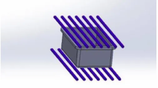
1.1.1 Parallel Cooling System
Parallel cooling channels are drilled straight channels that the coolant flows from a supply manifold to a collection manifold. Due to the flow characteristics of the parallel cooling channels, the flow rate along various cooling channels may be different, depending on the flow resistance of each individual cooling channel. This varying of the flow rate, in turn, causes the heat transfer efficiency of the cooling channels to vary from one to another. As a result, cooling of the mold may not be uniform with a parallel cooling channel configuration.
[image:1.612.316.569.526.667.2]© 2016, IRJET | Impact Factor value: 4.45 | ISO 9001:2008 Certified Journal | Page 847 1.1.2 Series Cooling System
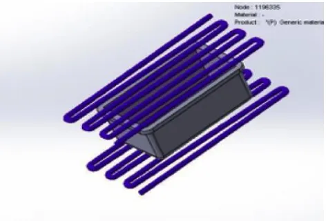
Cooling channels that are connected in a single loop from the coolant inlet to its outlet are called serial cooling channels. This type of cooling channel network is the most commonly used in practice. By design, if the cooling channels are uniform in size, the coolant can maintain its turbulent flow rate through its entire length. Turbulent flow enables the heat to be transferred more effectively. For large molds, more than one serial cooling channel may be required to assure a uniform coolant temperature and thus uniform mold cooling.
Fig -2 Series Cooling System
1.2 Robust Cooling System
[image:2.612.38.274.250.410.2]Robust cooling system is modified form series cooling system design to facilitate uniform cooling of molded part and reduce overall cooling time of injection molding process cycle.
Fig -3 Robust Cooling System
1.3 Conformal Cooling System [2]
Conformal cooling system is new approach for designing cooling channels for molded part. Conformal cooling channels are conformal to the contour of the part to be cooled. Conformal cooling channels allow the coolant to access all part locations uniformly, making the cooling process efficient and consistent. It is not always possible to reach all part areas with conventional methods. Depending on how much of the volume is accessible, the cycle time can increase significantly. Conformal cooling also reduces scrap rates; this is in part due to the reduction in the temperature variation across the part.
Fig -4 Conformal Cooling System
2. MANUFACTURING OF CONFORMAL COOLING
SYSTEM
DMLS is the most prominent AM technique for
manufacturing conformal cooling molds. There are several other techniques outside of additive manufacturing being employed including vacuum diffusion bonding and liquid interface diffusion.
2.1 Direct Metal Laser Sintering (DMLS) [3]
[image:2.612.316.564.262.407.2]© 2016, IRJET | Impact Factor value: 4.45 | ISO 9001:2008 Certified Journal | Page 848 for complex oil and gas components, custom medical guides,
consolidated aerospace parts, and tough functional prototypes.
2.2 Vacuum Diffusion Bonding [4]
Vacuum diffusion bonding relies on temperature, pressure, time, and (ultra low) vacuum levels to facilitate atomic exchange across the interface between the materials. The process will work on similar or dissimilar materials so long as they are in intimate contact with one another. Vacuum diffusion bonding can be performed with or without pressure being applied and with or without the assistance of a short-lived low melting point “filler metal” (i.e. “activation layers or interlayer”) to facilitate the joining process. The result of the process is joints suitable for use by a variety of industries, including aerospace, medical, chemical,
electronic, optics, energy and instrumentation. This method can be used for mold manufacturing of conformal cooling.
2.3 Liquid Interface Diffusion [4]
A liquid interface diffusion bonded composition comprises a metal honeycomb core such as a titanium honeycomb core and a metal facing sheet such as a titanium-facing sheet bonded thereto. The composition is prepared by a method comprising: (a) providing a metal honeycomb core having a faying surface and a metal facing sheet having a faying surface; (b) placing together the honeycomb core faying surface and the facing sheet faying surface, and providing there between a metal foil typically formed by a rapid solidification process or a melt spinning process,; (c) subjecting the faying surfaces and metal foil there between to sufficient positive pressure to maintain position and alignment for joining; and (d) heating the faying surfaces and metal foil there between in a protective atmosphere to a temperature for required time to cause a melt of the metal foil. The composition and method of this invention are useful in applications where high strength, lightweight materials are required, such as in aircraft and aerospace-related structures.
3. DESIGN METHODOLOGY AND LITERATURE
REVIEW
In this paper computer simulation is carried out for ABS material. Design of cooling system channels are according to following instructions [5]:
i) The circuits of the water should be symmetrical and independent relatively to the filling zones and impression(s) of the mold;
ii) Thermal variations in the walls of the impressions shouldn’t be pronounced, so the lines of water should be designed in function of its distance to the impression walls’;
iii) The cooling fluid input and output should be placed for the mold backwards (opposite side to the operator);
iv) It’s important to guarantee that the cooling flow in the channels be turbulent.
Table -1 Cooling Channel Design Instructions [2]
Wall thickness of molded product in (mm) Hole diameter in (mm) Centerline distance between holes Distance between center of holes
and cavity
b a c
00-02 04-08 (2-3) x b (1.5-2) x b
02-04 08-12 (2-3) x b (1.5-2) x b
04-06 12-14 (2-3) x b (1.5-2) x b
3.1 Simulation Conditions
Melt temperature = 230 0C
Minimum coolant temperature = 25 0C
Air temperature = 30 0C
Mold open time = 5-7 sec
Coolant flow rate = 150 cc/sec
Ejection temperature = 90 0C
3.2 Materials
Coolant = water
Part material = ABS
© 2016, IRJET | Impact Factor value: 4.45 | ISO 9001:2008 Certified Journal | Page 849
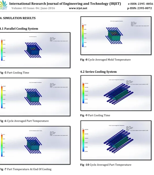
4. SIMULATION RESULTS
4.1 Parallel Cooling System
Fig -5 Part Cooling Time
[image:4.612.39.573.43.649.2]Fig -6 Cycle Averaged Part Temperature
Fig -7 Part Temperature At End Of Cooling
Fig -8 Cycle Averaged Mold Temperature
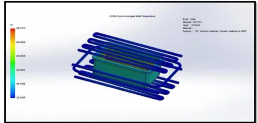
4.2 Series Cooling System
Fig -9 Part Cooling Time
© 2016, IRJET | Impact Factor value: 4.45 | ISO 9001:2008 Certified Journal | Page 850 Fig -11 Part Temperature At End Of Cooling
Fig -12 Cycle Averaged Mold Temperature
[image:5.612.313.567.285.407.2]4.3 Robust Cooling System
Fig -13 Part Cooling Time
Fig -14 Cycle Averaged Part Temperature
Fig -15 Part Temperature At End Of Cooling
Fig -16 Cycle Averaged Mold Temperature
[image:5.612.314.566.483.603.2]© 2016, IRJET | Impact Factor value: 4.45 | ISO 9001:2008 Certified Journal | Page 851 Fig -17 Part Cooling Time
Fig -18 Cycle Averaged Part Temperature
Fig -19 Temperature At End Of Cooling
Fig -20 Cycle Averaged Mold Temperature
[image:6.612.34.290.95.382.2]5. Comparisons Of Simulation Results
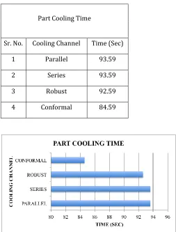
Table 1 Part Cooling Time
Part Cooling Time
Sr. No. Cooling Channel Time (Sec)
1 Parallel 93.59
2 Series 93.59
3 Robust 92.59
4 Conformal 84.59
[image:6.612.315.568.142.475.2]Chart -1 Part Cooling Time
Table 2 Averaged Part Cooling Time
Averaged Part Cooling Time
Sr. No. Cooling Channel Time (Sec)
1 Parallel 55.7
2 Series 55.8
3 Robust 54.91
[image:6.612.35.289.408.535.2]© 2016, IRJET | Impact Factor value: 4.45 | ISO 9001:2008 Certified Journal | Page 852 Chart -2 Averaged Part Cooling Time
Table 3 Averaged Part Temperature
Averaged Part Temperature
Sr. No. Cooling Channel Temperature (0c)
1 Parallel 111.27
2 Series 111.32
3 Robust 110.99
4 Conformal 106.15
[image:7.612.309.569.109.456.2]Chart -3 Averaged Part Temperature
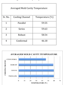
Table 4 Averaged Mold Cavity Temperature
Averaged Mold Cavity Temperature
Sr. No. Cooling Channel Temperature (0c)
1 Parallel 59.55
2 Series 59.63
3 Robust 58.54
4 Conformal 46.18
Chart -4 Averaged Mold Cavity Temperature
Table 5 Comparisons With Parallel Cooling System
Reduction Of Various Parameters
In Comparison With Parallel System
Cooliing
Systems
Part
Cooling
Time
(sec)
Averaged
Part
Cooling
Time
(sec)
Averaged
Part
Temperature
(0C)
Averaged Mold
Cavity
Temperature
(0C)
© 2016, IRJET | Impact Factor value: 4.45 | ISO 9001:2008 Certified Journal | Page 853
Robust 1 0.79 0.28 1.01
Conformal 9 13.27 5.12 13.37
6. CONCLUSIONS
Simulation results and direct comparison of various cooling systems that are in practice as of now we can say that conformal cooling system gives better cooling results in all parameters. Part cooling time and averaged part cooling time is considerably reduced. Averaged part and averaged mold cavity temperature is less than other cooling systems, which shows uniform cooling of part and readiness of mold for next batch production respectively.
This concludes that besides difficulty in manufacturing conformal cooling system is appropriate cooling system for plastic injection molding.
REFERENCES
[1] Cracknell, P. D. Handbook of Thermoplastics Injection Mould Design, Springer, Netherlands, (2014).
[2] M. Hall, M. Krystofik, Conformal Cooling . white paper, Rochester Institute of Technology, (2/10/2015 ).
[3] S. L. Ford, “Additive Manufacturing Technology: Potential Implications for U.S. Manufacturing Competitiveness,” Journal of International Commerce & Economics, (2014, September). [4] Ian Gibson, D. R. Additive Manufacturing
Technologies 3D Printing, Rapid Prototyping, and Direct Digital Manufacturing. London: Springer New York Heidelberg Dordrecht.
[5] Cooling Systems in Injection Moulds. School of
Technology and Management, Polytechnic Institute of Leiria. Leiria: CAE DS – Mould and Die Design.
[6] V. Filiposki, J. Chaloska “Analysis Of Injection Molding Cooling Systems And Its Effects On The Ejection Time Of The Part At Thermoplastic Injection Molding,” Journal for Technology of Plasticity , 40 (Number 1), (2015).
[7] M. Khan, S. K. Afaq, N. U. Khan and S. Ahmed, “Cycle Time Reduction in Injection Molding Process by Selection of Robust Cooling Channel Design,”ISRN Mechanical Engineering , Volume 2014 (article ID 968484), 8,
[8] X. P. Daang, H. S. Park ,”Design and Simulation-Based Optimization of Cooling Channels for Plastic Injection Mold,” university of Ulsan, South Korea