© 2015, IRJET ISO 9001:2008 Certified Journal
Page
1470
Performance Testing Of 2-Stroke SI Engine by Using External Vaporized
Carburetor
Ashish D. Sonparate
1, Sneha P.Gadpayle
2, Poonam P. Bajpai
31
Assistant Professor, Mechanical Engineering Department, PIET, Nagpur-19, Maharashtra, India
2
Assistant Professor, Mechanical Engineering Department, PIET, Nagpur-19, Maharashtra, India
3
Assistant Professor, Mechanical Engineering Department, PIET, Nagpur-19, Maharashtra, India
---***---Abstract -
— The general demand in the market todayis for two wheelers with excellent fuel economy, superb power performance and cleaner & greener emissions. A simple device for mixture preparation in a spark ignition engine (external vaporizing carburetor) with the ability to provide the engine with a homogeneous and correctly proportioned combustible mixture for different operating conditions has been tested in this study. This carburetor works on the principle of adiabatic vaporization of liquid gasoline fuel before introduction into the engine cylinder. This vaporization is achieved by passing atmospheric air suck by blower, the blower is used to pass atmospheric air forcefully into the chamber through perforated tube. The chamber contain petrol up to perforated tube level. One opening is given to the chamber for supply air-fuel mixture to the carburetor in vapor form. The performance and exhaust gas emissions of the engine were studied using gasoline and oil (lubricating oil), using both conventional and vaporizing carburetors. Results have shown that the vaporizing carburetor has numerous advantages over conventional carburetors. The advantages include improvement in fuel economy and exhaust emission, which can be attributed to the leaning out of the mixture that could be prepared by using the external vaporizing carburetor.
Keywords
:Bajaj Bravo 150cc- Air Cooled -2 Stroke
SI Engine; Externally Vaporizing Carburetor;
Mixture Preparation; Engine Performance.
1. INTRODUCTION
Spark ignition engine performance is greatly affected by the quality of air fuel mixture through the intake system, so the good design of the mixture preparation system will enable the engine to operate at its best performance. Metering of fuel and air in suitable proportions, mixing and distributing the fuel across the air stream and leading the mixture to the intake manifolds is usually accomplished through a mechanically controlled device which may be a carburetor. For the air fuel mixture to be combustible, the fuel should be atomized, mixed
with air and vaporized as it owns through the induction manifold to the combustion chamber. Atomization, mixing, vaporization, homogeneity and correct proportionality are very important parameters that make an air fuel mixture suitable for engine operation. Also, these processes require a finite time to occur, therefore, speed is quite important.
Most conventional carburetors do not deliver optimum, uniform mixtures to every cylinder at different operating conditions. Optimum fuel air ratio at any given speed is that which will de-velop the required torque, or brake mean effective pressure, with the lowest fuel consumption consistent with smooth and reliable operation. Mixture strength varies from cylinder to cylinder and from cycle to cycle. This is due to insufficient mixing and vaporization of fuel i n air in the intake manifold. I n summary, a conventional carburetor under normal operating conditions supplies the engine with a non homogeneous mixture containing part of the fuel in a liquid form which, i f not completely evaporated before combustion, can cause cyclic variation, increase the concentration of unburned hydrocarbons and ruin lubricating oil quality by oil dilution. Many attempts have been made to improve mixture quality to supply the engine with a well vaporized and mixed charge, such that engines will run reliably with best economy. Attempts include:
using gaseous fuels, e.g. methane, increasing the rate of turbulence to improve mixing of fuel vapors with air,
Developing other types of venturi carburetors that are more suitable for efficient engine operation.[4]
© 2015, IRJET ISO 9001:2008 Certified Journal
Page
1471
the two wheeler generally bought by the public havecharacteristics which include very high levels of pollution caused by scavenging losses, un-economical operation because of fresh charge losses, less scope for lean operation and no control on the engine once the valves have closed. Therefore the goal of this paper is to design such a carburetion system which achieves optimum emission values and in addition to improve the fuel efficiency of the engine.[3]
2.
CONVENTIONAL CARBURETOR
Fig.2.1 Conventional Carburetor
The modern carburetor consists essentially of a main air passage through which the engine draws its supply of air, mechanisms to control the quantity of fuel discharged in relation to the flow of air, and a means of regulating the quality of air/fuel mixture delivered to the engine cylinders.
The essential parts of the carburetor are:
a. Tickler b. Choke valve c. Venturi d. Throttle valve e. Idling system f. Float chamber g. Starting pump h. Accelerating system
a. Tickler
These are devices used to cause flooding of carburetor at the start. By depressing the tickler, the float is depressed thereby providing more fuel. These were commonly used in old motorcycle carburetor.
b. Choke valve
This is the simplest butterfly valve fitted at the top of air horn. It may be operated by hand or it may be automotive for starting choke is used so that very small amount of air gets past it and throttle valve is open due to which whole of suction is applied to nozzle which delivers sufficient fuel to provide a mixture rich in quantity, though small in quantity. The choke valve must be open immediately when the engine starts otherwise engine cylinder will be flooded with fuel, which would cause it to stall. This is helped by any of following methods. By mounting the choke eccentrically with this when the engine starts the forces due to pressure on the two sides of choke spindle are unequal, their difference producing a turning moment to open the choke.
By use of stranger valve fitted on the choke. As soon as engine started the air pressure forces open the strangers against the spring pressure and the air enters the carburetor avoiding mixture being over-rich. By this time the driver also presses the choke to open choke valve.
c. Venturi
The venturi is simply a restriction in the air passage. Here the passage area is minimum thus die to less area the air velocity increases and because of this increase in velocity decrease in pressure is caused at the nozzle which is located in venturi itself. Due to this depression being applied at nozzle the fuel comes out is vaporized by coming air streams.
d. Throttle valve
The pressure of throttle is to control the quantity of air fuel mixture. It is attached to the accelerator pedal by means of suitable linkage so that when pedal is depressed the valve opens out. The throttle valve is of two types.
1. Butterfly Valve 2. Cylindrical Valve
© 2015, IRJET ISO 9001:2008 Certified Journal
Page
1472
Metering rod consists of number of steps ofdiameter sizes at its bottom and is connected with accelerator pedal through linkage when accelerator pedal is pressed the throttle is held wide open and metering rod is lifted up. In this condition smaller diameter of rod is inside fuel hole providing larger flow area thus delivering more fuel.
e. Idling System
An idle port controlled by adjusting screw is provided in the engine side of throttle valve. As throttle is almost closed the engine suction is applied at the pilot petrol jet which supplies petrol the jet itself draws petrol form main jet circuit. The air is drawn in form main jet circuit. The petrol and air mix in idle passage and the mixer comes out of idle port. To ensure that smooth transfer from idle and low speed circuit to main jet circuit without the occurrence of float spot slow running openings are provided on venture side of throttle valve. As throttle valve is opened wide suction at idle port is decreased.
f. Float chamber
The float chamber as usual contains a float. A needle valve closes the valve inlet when the fuel in float chamber attains a specified level when the fuel level falls; the needle valve opens the inlet to admit the more fuel .
g. Starting Pump
The starter valve is in the form of a float disc with the holes of different sizes. These holes connect the petrol jet and the starter jet sides to passage which opens into the air horn just below the throttle valve. Depending upon the position of the starter lever. Which can be adjusted by the drive on the dashboard, either bigger or smaller holes comes opposite the passage. Initially for starting richer mixture is required and after the engine starts the richness-required decreases. So in the start position bigger holes are connecting holes. The throttle valve being in the close position the whole of the engine suction is applied to starting passage.
1. Due to this petrol from the float chamber passes through the starter petrol
jet and rises into passage
2. Some of it comes out and mixes with the air entering through air jet. Jet and
passages are so shaped that mixtures supplies to carburetor is rich enough for starting. After the engine has started the starter lever is brought to second position in between the initial and final position. Now the smaller hole in the valve completes the circuit, thus reducing the amount of petrol. Also in this position the throttle valve is partly open, so that petrol is also coming out form main jet. The reduced mixture supply form the starter system till it riches the normal running temperature when the starter is brought to off position.
h.
Acceleration Pump
To avoid float spot during acceleration, a separate membrane pump is provided which delivers spurts of extra needed fuel for acceleration. Pump lever is connected to accelerator pedal so when the same is pressed, the lever moves to left thrust pressing the membrane towards left and forcing petrol into main jet circuit. When the pedal is left free, the lever moves the membrane back towards right creating vacuum toward left which opens the ball valve provided and thus admits the petrol from chamber into a pump.
In a conventional spark-ignition engine, the fuel and air are homogeneously mixed together in the intake system, inducted through the intake valve into the cylinder where it mixes with residual gases and is then compressed. Under normal operating conditions, combustion is initiated towards the end of the compression stroke at the spark plug by an electric discharge. A turbulent flame develops following the ignition and propagates through this premixed charge of fuel and air, and also the residual gas in the clearance volume until it reaches the combustion chamber walls.
3.HISTORY OF VAPORIZED CARBURETOR
© 2015, IRJET ISO 9001:2008 Certified Journal
Page
1473
apparent for low speed and low load operations whenthe intake air velocity is too low to effectively wake the fuel droplets. The fuel injection system, employed for some I.C. engines today alleviate the problem to some extent by injecting the liquid fuel directly into the intake air stream via nozzle to produce final droplets and providing a more precise air fuel mixture. Unfortunately even the final droplets remain mostly in the liquid form.
The most common design to vaporize the fuel is to provide an exhaust gas heated, engine coolant heated or electrically heated heat exchanger in between the conventional carburetor and intake manifold. The main disadvantage of this type of design is the overall heating of intake air. This heating tends to promote detonation; the uncontrollable ignition of the fuel mixture inside the engine cylinder. Another disadvantage is the reduction of the maximum power output of the engine. As the intake air temp increases, the air mass going into the decreases due to the physical property that at higher air temperatures, the air density is lowered. In effect the maximum power produced by the fuel and air explosion is lessened. Some of these designs divert the proportion of intake air and fuel into the heat exchanger. Subsequently, only a portion of the fuel is vaporized and the majority of the fuel is still in liquid form. In engine coolant heated system, the temp of the engine coolant is not higher enough for fuel vaporization. In electrically heated system, extra batteries may be needed for providing the electrical power to the heat exchanger, and in general extra engine power is needed to generate this electricity to be effective.
Another approach is a standalone carburetor which consists of a few basic modules for conditioning the fuel. This is the approach this invention is based on. Commonly, this design has four basic modules; they are a fuel atomization chamber a heat exchanger, heat exchanger temp control apparatus and fuel metering mechanism. Earlier attempts usually employ mechanical spray for fuel atomization with bulky heat exchanger, simple heat exchanger temp control and fuel metering mechanisms. [8]
4. PRINCIPLE VAPORIZING CARBURETOR
Fig. 4.1. Schematic of vaporizing carburetor.
5. EXPERIMENTAL SETUP OF VAPORIZED
CARBURETOR
The above schematic is of Vaporized Carburetor. The main parts of vaporizing carburetor are:
a) Vaporizing chamber b) Blower
c) Venturi d) Throttle valve e) Fuel tank
a) Vaporizing chamber
It is made of a transparent plastic cylinder of 90 mm diameter and 180 mm long. A 20 mm diameter intake central tube which is made perforated up to certain level from its bottom. The lower end of the tube is closed and rests against the bottom cover of the cylinder. An opening in the bottom of the cylinder is made for fuel inlet from the tank.
The opening to supply the vapour to the venturi is made at some higher level in order to avoid mixing of gasoline with vapors. [2]
b) Blower
For maintaining constant supply of air under pressure required to form gasoline vapors a blower is used, which suck the atmospheric air and send to the vaporizing cylinder through perforated tube.[6]
c) Venturi
The vapour form in vaporizing chamber is suck in to the venturi, due to the suction created by the engine.
d) Throttle Valve
The pressure of throttle is to control the quantity of vapour. It is attached to the accelerator pedal by means of suitable linkage so that when pedal is depressed the valve opens out and accordingly vapors are supplied to the engine cylinder.
e) Fuel Tank
© 2015, IRJET ISO 9001:2008 Certified Journal
Page
1474
6. MEASUREMENT AND TESTING
In order to compare the performance of engine by using vaporizing carburetor with that of by using conventional carburetor, For this purpose we have to measure the various parameters using the various equipments and by conducting the various tests on the engine. Also we have to compare the engine in terms of its output and efficiency. Towards this end we have to test the engine and make measurements of relevant parameters that reflect the performance of the engine. It is beyond the scope of this report to discuss all the factors. In this chapter certain basic important measurements and tests are considered.
Measurement of various Basic parameters
6.1 Air consumption 6.2 Fuel consumption 6.3 Brake power 6.4 Speed of engine
6.1
Air Consumption Measurement
The mass of air inducted in the engine has to be measured to calculate the air fuel ratio. For the purpose of the measurement of air we use the air box method. The basic principle in this method is of orifice method.
The orifice method can be used if pressure pulsations could be damped out by some means. The usual method of damping out pulsations is to fit an air box of suitable volume (200 times the swept volume of the engine which is the 150 c.c. for our engine) to the engine with an orifice in the side of the box remote from the engine.
[image:5.595.340.550.227.336.2]We are using the U- tube for the measurement of pressure inside the air box. From air box we get the pressure in terms of height of water column. We are also using the diaphragm for the purpose of damping the pulsations.
Fig 6.1: AIR BOX
6.2
Fuel Measurement
This method consist of spherical glass burette which is calibrated for taking measurement for fuel consumption, as shown in fig. it is connected by a valve at its base to control the flow of fuel to the engine in order to avoid the error in sighting the fuel level against the mark on the burette photocells are used.
Fig 6.2: BURETTE
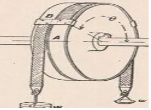
6.3 Brake Power
Measurement of brake power is one of the most important measurements in the test schedule of an engine. It involves the determination of the torque and the angular speed of the engine output shaft. The torque measuring device is called a dynamometer. A rotor driven by the engine under test is attached to stator with the help of rope; this type of dynamometer is called the rope brake dynamometer. The rope brake dynamometer as shown in fig is another simple device for measuring BP of the engine. It consists of rope wound around the rotating drum attached to the output shaft. Both sides of the ropes are connected to the spring balance. The power absorbed is due to the friction between the rope and the drum. The drum therefore requires cooling. Rope brake is quit cheaper and can be easily fabricated but not very accurate because of changes in the friction coefficient of the rope with temperature.[7]
[image:5.595.350.505.616.729.2]© 2015, IRJET ISO 9001:2008 Certified Journal
Page
1475
6.4
Speed Measurement
[image:6.595.320.583.103.409.2]Speed measurement is an art. Speed of the engine is widely used in the computation of power, design and development. Measurement of speed is accomplished by instruments like mechanical counters and timers, mechanical tachometers, stroboscope, electric counters, tachometers, electric generators, electronic pulse counters etc. The measuring instrument we are using here for measuring the speed of the engine is hand digital tachometers.
Fig 6.4: HAND TACHOMETER
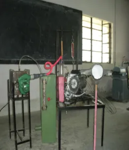
7. EXPERIMENTAL SETUP
[image:6.595.70.297.467.598.2]The experimental setup to study the direct air injection scavenged engine. [5]
Fig 7.1 : EXPERIMENTAL SETUP
1.AIR BOX , 2.BLOWER,3.VAPOURIZING CHAMBER, 4.FUEL TANK, 5. CARBURATTOR ,6.CRANKCASE, 7.ENGINE, 8.SPRING BALANCE 9.DYNAMOMETER, 10.TACHOMETER, , 11.MANOMETER, 12 BURRETE,
a.
Actual Setup
The selected engine is a Single Cylinder Two Stroke, 150 cc engine. The engine details are mentioned in appendix. A rope brake dynamometer which consists of rope, two spring balances as shown in the fig is used for loading the engine to measure brake power. The air flow is measured with the help of Air box, which pressure is measured with the help of U-Tube manometer, mounted itself on the air box. The fuel measurement is taken with the help of Burette which is calibrated. A tachometer along with digital rpm indicator is used to measure the speed of the engine.
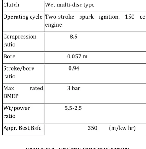
8. ENGINE SPECIFICATION
BAJAJ BRAVO 150CC, AIR COOLED 2 STROKE SI ENGINE:
TECHNICAL SPECIFICATIONS OF ENGINE
Performance
Peak power 8.0 hp at 5500 rpm
Highest power amongst 2-stroke scooters
Peak torque 1.35 Kg m at 3500 rpm
© 2015, IRJET ISO 9001:2008 Certified Journal
Page
1476
EngineType 5-port single
cylinder, 2-stroke with reed valve induction
Advanced engine for superior performance
Transmission 4-speed gear box Smooth easy shifting
Clutch Wet multi-disc type
Operating cycle Two-stroke spark ignition, 150 cc engine
Compression ratio
8.5
Bore 0.057 m
Stroke/bore ratio
0.94
Max rated BMEP
3 bar
Wt/power ratio
5.5-2.5
[image:7.595.314.561.103.356.2]Appr. Best Bsfc 350 (m/kw hr)
TABLE 8.1: ENGINE SPECIFICATION
9.
TESTING
9.1
Observation
1. Diameter of orifice = 14.13mm 2. Swept volume = 150cc
3. CV of fuel = 45000kJ/kg 4. Specific gravity of fuel = 0.78 5. Diameter of brake drum = 23cm 6. Room temp = 303k
9.2
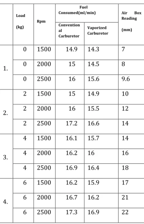
Observation Table
Following table is tabulated with the help of net fuel consumption calculated for 3 different RPM’s with the help of conventional as well as vaporized carburetor. Following table shows the brief comparison between the two:
9.3 Performance Evaluation
Here performance evaluation for the conventional Two Stroke SI Engine by taking the observations reading of various parameters for both with and without direct air scavenging system. Here in this table comparative observations of both readings are made in an accurate way. [1]
Sr. No.
Load
(kg)
rpm
B.P.
Watt
Bsfc (kg/KW-hr) ma/mf for
Vaporized
Carbureto r Conventional
Carburetor
Vaporized Carburetor
1
0
0 1500 _ _ _ 4.79
0
0 2000 _ _ _ 5.033
0
0 2500 _ _ _ 5.123
2
2
2 1500 434.54 0.0269 0.0267 5.50
2
2 2000 579.39 0.0215 0.0208 5.784
2
2 2500 724.24 0.0185 0.0178 5.841
3
4
4 1500 869.06 0.0144 0.014 6.176
4
4 2000 1158.79 0.0109 0.0107 6.474
4
4 2500 1448.49 9.1×10⁻³ 8.82×10⁻³ 6.712
4
6
6 1500 1303.64 9.69×10⁻³ 9.51×10⁻³ 6.715
6
6 2000 1738.19 7.49×10⁻³ 7.27×10⁻³ 7.326
6
© 2015, IRJET ISO 9001:2008 Certified Journal
Page
1477
TABLE 9.1: Difference between Conventional & Vaporized Carburetor
10.
RESULTS AND DISCUSSION
From the overall experimental setup is has revealed the effect of ENGINE improves the engine performance and exhaust emissions. From results it is almost clear that 2stroke SI engine gives more power for same fuel consumed, less emission as compared to conventional carburetor.
The improvement in the engine efficiency and the reduction in exhaust emissions when the vaporizing carburetor is used can be attributed to the following:
1. The degree of turbulence which improves vaporization and mixing of fuel vapor with air. Tur-bulence formed in the vaporizing carburetor is due
to air penetration through the central holes which increases the air velocity to enter the fuel layer and begin the process of atomization and vaporizing of fuel droplets. The degree of turbulence is directly related to engine speed.
2. Elimination of fuel droplets in the mixture. This will obtain a higher air fuel ratio and better distribution of fresh charge to each cylinder which, in turn, reduces cyclic and cylinder to cylinder variation and exhaust emissions.
0 3 6 9 12 15 18
0 500 1000 1500 2000 2500 3000
F U E L
C O N S U M E D
[image:8.595.320.519.230.420.2]Load Coventional
Fig.10.1.LOAD Vs FUEL CONSUMPTION
0 3 6 9 12 15 18
1200 1500 1800 2100 2400 2700
F U E L
C O N S U
M
E D
SPEED
Coventional Vapourized
Fig.10.2.SPEED Vs FUEL CONSUMPTION
11. CONCLUSIONS
Sr .
N o .
Load
(kg)
Rpm
Fuel
Consumed(ml/min) Air Box
Reading
(mm) Convention
al Carburetor
Vaporized Carburetor
0
1.
0
1500 14.9
14.3
7
0
2000 15
14.5
8
0
2500 16
15.6
9.6
0
2.
2
1500 15
14.9
10
2
2000 16
15.5
12
2
2500 17.2
16.6
14
0
3.
4
1500 16.1
15.7
14
4
2000 16.2
16
16
4
2500 16.9
16.4
18
0
4.
6
1500 16.2
15.9
17
6
2000 16.7
16.2
21
[image:8.595.320.518.468.699.2]© 2015, IRJET ISO 9001:2008 Certified Journal
Page
1478
1. For the same power output, an engine can operate
with leaner mixtures by using the externally vaporizing carburetor as opposed to a conventional carburetor, so the fuel consumption is considerably reduced, and the amount of exhaust emissions are reduced.
2. The construction of the vaporizing carburetor is
very simple, so its manufacturing cost is low when compared with conventional carburetors or fuel injection systems, and its maintenance is easier.
3. The engine can be successfully operated with the modified vaporized carburetor up to 4500 rpm.
4. Improvement in fuel efficiency and more complete
combustion of the modified engine were observed as compared to conventional carbureted engine.
REFERENCES
1. S.Kumarappa, G.P.Prabhukumar,
“Improving the Performance of Two Stroke Spark Ignition Engine by Direct Electronic CNG Injection”JJMIE, Volume 2, Number 4 (ISSN 1995-6665),2008.
2. Simon de Bruxelles, “Oil Industry Suppressed Plans for 200-mpg Car”,March 31, 2003, Charles Nelson Pogue: US Patent #1,759,354 ("Carburetor").
3. T.R.Ani1, S.D.Ravi, M.Shashikanth, P.G.Tewariand N.K.S.Rajan, “CFD Analysis
of a Mixture Flow in a Producer Gas Carburetor”, International Conference on Computational Fluid Dynamics, Acoustics, Heat Transfer and Electromagnetics CFEMATCON-06, July 24-25, 2006, Andhra University, Visakhapatnam – 530003, INDIA.
4. MohÕd Abu-Qudais, K.R. Asfar, Ramzi Al-Azzam, “Engine performance using vaporizing carburetor”, Energy Conversion and Management 42 (2001) 755-761
5. Mani, Kaushik, Jain, Vineet, “ Development Of Mechanical Gasoline Direct Injection (Gdi) Engines For 4 Stroke Two Wheelers” Manipal University, India, F2008-Sc-042.
6. Lars Grimsrud, “Carburetor Vacuum Ports: Manifold, Ported and Venturi Vacuum Explained”, The Ultimate Corvette Tuning and Beer Drinking Fraternity Lafayette, CO. Rev. New 9-10-03.