N A N O E X P R E S S
Open Access
Nonmechanical Infrared Beam Steering
Using Blue Addressed Quantum Dot Doped
Liquid Crystal Grating
Xiangru Wang
1*, Xiaoping Huang
2, Ziqiang Huang
3, Liang Wu
2, Jiyang Shang
4, Qi Qiu
1and Shuanghong Wu
1Abstract
We present a scheme of nonmechanical laser beam steering using ZnS/InP quantum dots doping nematic liquid crystal as the optical recording film. Because of its internal electric field generated by blue laser-induced charge carrier distribution, liquid crystal molecules are reoriented to form a phase grating which make the incident angle steer to the angle as we desire. Being a nonmechanical programmable laser beam steering, the anisotropy of the relative permittivity tensor and blue laser-induced electric carriers play a significant effect in determining the reorientable liquid crystal molecule and reconfigurable phase modulation of the gratings, that determines the steering angle and steering efficiency.
Keywords:Quantum dot, Liquid crystal grating, Nonmechanical beam steering
Background
Nonmechanical laser beam steering promises significant benefits to many free-space laser application, especially on those where precise pointing and tracking system are required, such as free-space optical (FSO) communica-tion, Lidar [1]. Many nonmechanical steering techniques have been suggested and studied including liquid crystal phase grating [2], MEMS [3], nanoscale optical antenna [4], gratings [5], fiber array [6], and so on.
Meanwhile, phase grating using the material of liquid crystal (LC) technology has undergone tremendous development not only on a single programmable device [7–10] but also on some integrated photonic devices due to its excellent electro-optic properties [11]. To be one of the most promising candidates to be a nonmechanical steerer, narrow steering range has been still a crucial short legs on one device. To accurately and efficiently steer optical beams over a large field of regard (FOR), the scheme of cascade system was proposed from an idea of N-nary numerical cascade system having multiple devices (M). And this M-bit-N-nary system was sug-gested to be used as numerical domain selection, and
the ordinary liquid crystal phase grating was used to be domain filling [12]
To realize a N-nary numerical laser steering, a couple of devices was invented including polarized prism [13], liquid crystal polarization grating (LCPG) (passive and active) [14, 15], multiplex volume Bragg grating (VBG) [16]. Generally, these numerical N-nary devices are all based on a general physics that: device should have a specific grating structure where the steering property is sensitive to the state of incident beam, and the state parameter could be polarization, incident angle, angular momentum, and so on. So, the value of N to realize a practical N-nary system is very limited to be binary for passive LCPG, quasi-ternary for active LCPG, and ternary for multiplex VBG. More importantly, steering angles of these N-nary devices are fixed and one-time written, but none is truly erasable or fully programmable.
In this letter, quantum dot doped liquid crystal (QD-LC) as the rewritable recording medium by blue laser [17], a
novel optical setup is proposed to succeed a
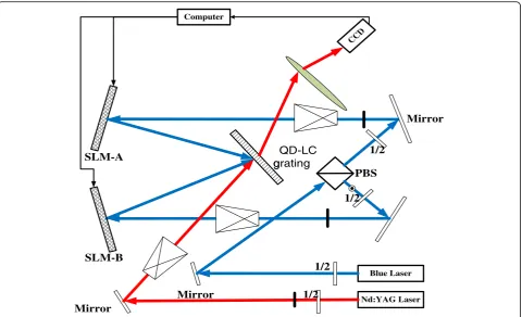
programmable diffractive grating on this QD-LC layer using two spatial light modulators to steer the writing coherent blue beams. As shown in Fig.1, on this novel blue laser-addressed grating, not only the grating period is programmable but also grating direction. To utilize the first order grating, the diffraction efficiency is required on * Correspondence:[email protected]
1School of Optoelectronic information, University of Electronic Science and
Technology of China, Chengdu 610054, China
Full list of author information is available at the end of the article
a very high level. Meanwhile, its response time is on the level of few milliseconds [18].
Methods
In our experimental setup shown in Fig. 1, from an optic-ally pumped single frequency MSL-FN-473 solid laser from CNI company with a wavelength of λB = 473 nm
and coherence length of longer than 50 m, the writing laser source are split into two beams which are set to be both s-polarized and intersected at an angle ofαAandαB
with respect to the x-axis, respectively, where the coordinate system is defined as shown in Fig. 2. The inci-dent angle of these two writing beams are realized by its given spatial light modulators (SLM) SLM-A and SLM-B. The incident plane (x-o-y plane) defined by the wave vec-tors of the two recording beams is perpendicular to the cell substrate. When their corresponding SLM does not load any data, i.e., direct reflection, QD-LC sample is titled at 45 with respect to the bisector of the two recording beams so that there is a projection of the grating vector
Nd:YAG Laser Blue Laser
CCD
Computer
SLM-A
Mirror
Mirror Mirror
PBS
1/2
1/2 1/2
1/2 SLM-B
QD-LC g
grating
Fig. 1Optical setup of QD-LC laser steering
[image:2.595.59.540.87.379.2] [image:2.595.57.544.543.715.2]onto the electric field vector to separate the electron-hole pairs easily.
The interference region is read by a linearly polarized coherent beam with a wavelength of 1064 nm, which is from a single mode coupled Nd:YAG laser with a power of more than 10 mW. Meanwhile, the reading near infrared beam propagates through the phase modulated QD-LC device with the angle of θinwith respect to the x-axis. After the phase modulation and fully interference, the reading beam is tilt to the direction ofθout.
Being a rewritable holography recording medium, quantum doping liquid crystal is similar withrevisable optical writing media such as photochromic polymers [17]. Because of its fast response and high photocon-ductivity [18], it has already been applied on the field of holographic glass-free 3D display. The grating formation is induced by orientational photorefractive (PR) effect related to photoexcitation and transportation of charge carriers [19]. Charge carriers (holes and electrons) are generated by pumped blue photons so as to form an internal field in the QD-LC mixture and boundary layer
interface. The distribution of charge carriers is modu-lated by interferometric fringe intensity, the grating direction of which is κg, as shown in Fig. 3a. Driven by
an external bias electric field E, the holes and electrons are trapped in the bright and dark regions, respectively, so as to form an enhanced spatially varying space charge field, as shown in Fig. 3b. Then, this spatially varying space charge field reorient the liquid crystal molecules to form a birefringence grating as show in Fig. 3c.
With the purpose of programming grating period and grating direction, according to the optical designed above, the value of grating direction θg and grating
periodΛare determined by
θg ¼αBþαA
2 ‐
π
2 ð1Þ
λBB 2Λ ¼ sin
αB−αA 2
ð2Þ
Meanwhile, according to the grating equation, we know, according to the theory of Kogelnik [20], if the
[image:3.595.54.540.354.704.2]incident beam propagates along the direction of first order diffraction angle
θin ¼αBþαA
2 þ arcsin λIR
Λ ð3Þ
it goes out with the angle perpendicular to the grating direction, being determined by
θout¼θg−π=2 ð4Þ
Substitute (1) and (3) into (4) and (2), respectively, Eqs. (2) and (4) are rewritten that:
sinαB−αA
2 ¼
λB
2λIR
sinðθout−θinÞ ð5Þ
αBþαA¼2θoutþ2π ð6Þ
For the given θout we desire, θin is always unchanged
after system initially being setup, the angles of two coherent writing beams αA and αB can be obtained
according to Eqs. (5) and (6), and realized by the non-mechanically spatial light modulator, where the phase on each electrode is governed by the method of variable blazing grating [2]. With respect to the normal direction of their given spatial light modulator, the steering angles of A and BαA/BandαBare determined by
sinαA=B¼ ΔϕA=B
k0d ð
7Þ
whereΔϕis the phase step between two adjacent pixels,d is the pixels period, k0 is the vacuum wave number of
addressing blue laser, i.e., the ideal phase retardation on the n-th electrode is the remainder ofnΔϕdivided by 2π.
[image:4.595.56.291.99.201.2]The blue addressed QD-LC phase plate is perfectly fabricated according the standard process of liquid crys-tal cell. Two ITO electrode coated fused silica were well pretreated after UV and DI water cleaning. After mech-anical rubbing on the polyimide layer coated on ITO substrates for homogeneous alignment, these two substrates are well aligned and spaced with a thickness of 30 μm by spherical spacers. Then, the working medium QD-LC material is a mixture of nematic liquid
Table 1Steering angle versus incident angles of blue laser
Desired θout
Theoretical results of Meas.
results ofθout
αA αB
−85.0° 81.04° 98.96° −84.99°
−87.5° 83.02° 96.98° −87.50°
−90.0° 85.00° 95.00° −90.01°
−92.5° 86.99° 93.01° −92.49°
−95.0° 88.99° 91.01° −95.01°
[image:4.595.59.540.397.707.2]crystal and ZnS/InP quantum dots, where the weight doping concentration is almost 1:20. Therein, the ZnS/ InP quantum dots must be firstly pretreated in a vacuum drying oven for roughly 10 h at 70oC so as to evaporate the chloroform and solvent. Finally, this mixture of QD-LC was filled in the empty liquid crystal cell mentioned above via capillary action at room temperature. Stainless pins are usually banded on the edge of ITO substrates to connect with electric driving circuit or driver.
Results and discussion
Initially, the incident angle of αA and αB are 85°and
95°(not loading data), respectively. Grating direction isx
axis, i.e., θg= 0, According to Eqs. (2) and (3), the initial
incident angle of infrared reading beam θin is 113.1°.
After loading, the driving data generated from computer to SLM-A and SLM-B, the steering out angle is measured by CCD camera and easily triangle geometrics. Table 1 shows the experimental measured result of steer-ing angle versus different steersteer-ing angle of SLM-A and SLM-B. It shows a good agreement with the theoretical results as we designed.
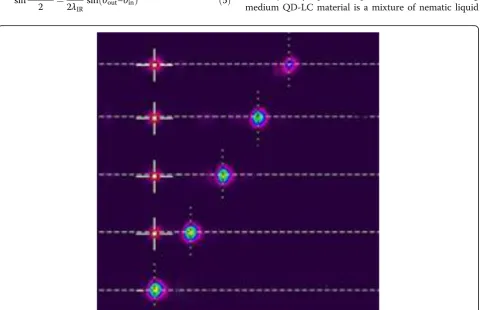
Meanwhile, the measured results and theoretical results are plotted in Fig. 4. Meanwhile, Fig. 4 shows the measured steering angles versus desired angle which is linear increasing. Furthermore, the captured beam pro-files of some issues are listed on the materials we used here are widely available, and the method is scalable, making this approach promising for future use in large size, dynamic, wide angle nonmechanical beam steering.
Importantly, because of the injection of blue address-ing laser on the device, those functional layers would play significant roles on blue laser absorption where it could result into heat deposition, particularly on the ITO layer. The additional heat deposition may lower the threshold of working laser power. However, addressing blue laser is usually on the level of mill watt per square centimeter, comparing with few watts or even kilo watts of the working infrared lasers on the potential applied fields such as laser communication, lidar, laser weapon. On the heat deposition, the contribution of addressing laser is quite small so that it is a neglectable issue. Meanwhile, with an infrared camera, we have not found any significant temperature rising.
Conclusions
In summary, we have established a study of nonmechani-cal laser beam steering system, where the phase grating of reading beam is recorded by using ZnS/InP quantum dots doping nematic liquid crystal film. We have shown that the birefringence of the liquid crystal is modulated by the internal electric field generated by the blue laser-induced charge carrier distribution. The behavior of reorientation of liquid crystal molecule forms a phase grating which
makes the incident angle steer to the angle as we desire, so as to a nonmechanical laser beam steering. In particu-lar, the anisotropy of the relative permittivity tensor and blue laser-induced electric carriers play a key role in deter-mining the reorientable liquid crystal molecule and recon-figurable phase modulation of the gratings, so that it would influence the efficiency and steering range of non-mechanical laser beams steering.
Abbreviations
FOR:Field of regard; FSO: Free-space optical; LC: Liquid crystal; LCPG: Liquid crystal polarization grating; MEMS: Micro electric mechanical system; QDLC: Quantum dot doped liquid crystal; SLM: Spatial light modulators; VBG: Volume Bragg grating
Acknowledgements
We gratefully acknowledge Najing Tech Cooperation for providing the quantum dot sample.
Funding
This work was supported under NSFC contract 61405029 and 91438108 and SAST 2015087.
Authors’Contributions
XW carried out the quantum dot liquid crystal device and thin films fabrication, experiment, data analysis, and paper writing. XH and ZH participated in paper writing. LW, JS, QQ, and SW participated in the very constructive discussion on the experiment setup. All authors read and approved the final manuscript.
Competing Interests
The authors declare that they have no competing interests.
Author details
1School of Optoelectronic information, University of Electronic Science and
Technology of China, Chengdu 610054, China.2School of Physical Electronics, University of Electronic Science and Technology of China, Chengdu 610054, China.3Research Institute Electronic Science and Technology, University of Electronic Science and Technology of China, Chengdu 610054, China.4Shanghai Aerospace Electronic Technology Institute Shanghai, Shanghai 201109, China.
Received: 2 December 2016 Accepted: 26 December 2016
References
1. Majumdar AK, Ricklin JC (2010) Springer Science & Business Media, vol 2 2. McManamon P F, Dorschner T A, Corkum D L (1996) Proc IEEE 84(2):268–298 3. Yoo B-W, Megens M, Sun T, Yang W, Chang-Hasnain CJ, Horsley DA, Wu MC
(2014) Opt Express 22:19029
4. Sun J, Timurdogan E, Yaacobi A, Hosseini ES, Watts MR (2013) Nature 493:195 5. Kwong D, Hosseini A, Covey J, Yang Z, Xu X, Subbaraman H, Chen RT (2014)
Opt Lett 39:941
6. Shay TM, Benham V, Baker JT, Benjamin W, Sanchez AD, Culpepper MA, Pilkington D, Spring J, Nelson DJ, Lu CA (2006) Opt Express 14:12015 7. Stockley J, Serati S (2004) Optical science and technology, the SPIE 49th
Annual Meeting. Int Soc Opt Photonics 32:32–39
8. Wang X, Wang B, Mcmanamon PF, Pouch JJ, Miranda FA, Anderson JE (2004) Int Soc Opt Photonics 782:782–791
9. Xinghua W, Bin W, Bos Philip J, McManamon Paul F, Pouch John J, Miranda Felix A, Anderson James EJ (2005) Appl Phys 98:073101 10. Wang X, Wang B, Bos PJ, Anderson JE, Pouch JJ, Miranda FA,
McManamon PF (2004) OSA technical digest 11. Serati S, Stockley J (2003) IEEE Aerosp confer 2003:5
12. McManamon PF, Bos PJ, Escuti MJ, Heikenfeld J, Serati S, Xie HK, Watson EA (2009) Proc IEEE 97:1078
13. Wu L, Mazilu M, Krauss TF (2003) J Lightwave technol 21:561
15. Kim J, Miskiewicz MN, Serati S, Escuti MJ (2015) Lightwave technol J 33: 2068–2077, ISSN 0733
16. Yaqoob Z, Arain MA, Riza NA (2003) Appl Opt 42(26):5251 17. Chen CP, Su Y, Jhun CG, J. J (2014) Opt photonics 1:1–8
18. Li X, Ping Chen C, Li Y, Zhou P, Jiang X, Rong N, Liu S, He G, Lu J, Su Y (2016) J J Display technol 12(4):362
19. Khoo C, Li H, Liang Y (1994) Opt Lett 19.21:1723 20. Kogelnik H (1969) Bell Syst Tech J 48(9):2909
Submit your manuscript to a
journal and benefi t from:
7Convenient online submission 7Rigorous peer review
7Immediate publication on acceptance 7Open access: articles freely available online 7High visibility within the fi eld
7Retaining the copyright to your article