© 2017, IRJET | Impact Factor value: 5.181 | ISO 9001:2008 Certified Journal | Page 2602
COMPARATIVE STUDY OF CODAL PROVISIONS FOR PRE-ENGINEERED
BUILDINGS
Vishwanath Pujar
1, Prof. Ravi Tilaganji
21
M.Tech Student, construction Technology, Department of Civil Engineering, Jain College of Engineering Belagavi,
Karnataka, India
2
Assistant Professor, Department of Civil Engineering, Jain College of Engineering Belagavi, Karnataka, India
---***---Abstract -
For a construction of single storey industrial building the pre-engineered building (PEB) is a new thought in the construction field. It is a concept of steel structures introduced in early 1960’s. In this type of construction the entire structure uses of built up “I” sections, the main advantage in this concept is no welding process will be carried out in the site. The structure will be designed and manufactured in the plant and are transported to the site and then erected. The sectional properties will depends on the moments at those specific locations hence there won’t be any excess of steel utilisation. In this study, an industrial ware house is analyzed and designed according to Indian standards, I.S. 800-2007 and also referring MBMA- 2002/AISC-89 with members built up, rectangular and tapered sections. In this study, a structure with a length of 30m,width of 20m, clear height of 9m and roof slope of 1: 10 is considered to carry out analysis and design(The members are assigned with the built up sections of rectangle and tapered sections).The behaviour and economy of the structure is discussed with respect to its analysis results and weight, between Indian code (IS 800 -2007) and American code (MBMA- 2002, AISC-89). In this study the structures considered was analyzed and designed with structural engineering software STAAD.Pro.
Key Words: Pre-Engineered Building, Rectangle Sections, Tapered Sections, MBMA- 2002/AISC-89, I.S. 800-2007.
1. INTRODUCTION
1.1 General:
In all parts of the earth almost steel industry is growing quickly. When there is a situation of resources availability, use of steel structures is economical solution, here word “economical” is used by considering duration and expenditure. The more important aspect in steel structures is time; these are built in very minimum duration of time. For the construction within the short duration, one such method is pre-engineered building construction. These are the buildings consists of steel sections, more amount of steel is avoided by considering the tapered section as per requirement of various analysis. Much more people are not aware of these kinds of structures but someone has to think about its prospect. Regular steel construction requires long
duration and more expenditure, hence construction stages consumes more time and cost it results in an uneconomical. In these, type of buildings the all fabrication is done in factory, based on the design, pre fabrication is been carried out for the members. After that transportation of members to the site and the process of erection is carried out in a less duration.
The performances of these buildings is structurally well understood, to ensure the satisfactory behaviour in high winds for the most part the code provisions are currently in place and adequate. The dismantling process of steel structures is easy because these buildings are connected with the bolts. When compared with strength to weight ratio the steel structures have better ratios than RCC structures. These members can be reused after dismantled.
1.2 Conventional steel building:
Steel structures are low rise with the truss system of roofing with roof coverings are termed as conventional steel buildings. For these kind of structures can be utilisation of various types of the roof trusses. According to pitch of truss the type of roof system is used. The steel structures also termed as metal structures. In this construction process producing the shapes of structural steel material used is steel. The shape of steel structure is unique, built with a specific cross section and also including certain chemical composition.
1.3
Pre-Engineered Building and it’s
Components:
These buildings are the composed with the combination of various sections they are built up sections, hot rolled sections and the elements of cold formed sections. The basic steel frame work is provided by these elements. For roofing and wall cladding with a selection of sheeting of single skin with added insulation or insulated sandwiched panels are provided.
1.3.1 Component of Pre-engineered Building:
© 2017, IRJET | Impact Factor value: 5.181 | ISO 9001:2008 Certified Journal | Page 2603 Main Frame
Secondary frame
Material for Sheeting (or) cladding Accessories
For the construction of these structures use of hot rolled tapered sections for primary framing and cold formed sections such as “Z” and “C” may be used as per the internal requirements for the stress for secondary framing, thus the control of wastage of steel and the own weight of the structure and hence lighter foundations. These kinds of structures are basically rigid jointed structure frames from hot rolled or cold formed sections, the roofs and side wall cladding is supported by main and secondary frames by purlins and sheeting rails. For the selection of PEB roof slope is selected from 5 to 12 degree, because of least volume of air occupied during heating and cooling of the structure.
To achieve the reduction in time of design, fabrication and installation the pre-engineered building system concentrates on use of pre-designed connections and pre-determined material stocks for structure to design and fabricate
1.4 Technical Parameters of Pre-engineered
Building:
PEBs are termed for detailed measurements. These are designed to provide the comfort to clients and to meet their requirements. The dimensions of the members are designed and produced to meet accuracy in standards. The measurements for the requirements of the structure are taken accurately. Some of the basic parameters that can be taken are: Span of the building, Length of the building, Height of the building, Sloop of the roof, Bay spacing, and Clear span.
1.5 Applications of Pre Engineered buildings (PEB):
This type of building system is new concept in structural engineering field, found itself in a construction and the erection variety building structures, this concept have widely used for Ware Houses, Workshops, Gas Stations, Parking for Vehicle Sheds, Showrooms, Aircraft Hangers, Roofs of Indoor Stadium, Canopies for Outdoor Stadium, Bridges, Railway platform Shelters and Industrial sheds.
1.6 Advantages of Pre Engineered buildings (PEB):
After the study shows that the use of PEB will decrease duration of construction of the project by at least less than time required by conventional Steel structures. Due to modern systems approach, there is saving in design, production of members and on site erection costs. Steel structures are completely manufactured in factory in the presence of controlled conditions hence the quality control is assured. The applications of PEB are Ability to span long distances, Faster occupancy, Cost efficient, Low cost
maintenance, Architecture design are unique and aesthetically pleasing , Reduction in time, Structures are light weight, Greater durability, Higher tensile strength, Provides flexibility in expansion, Quality control is assured.
2. METHODOLOGY
The details of various steel structural configurations are explained and details of the members and their properties are discussed. Normal steel structures and pre-engineered structures are discussed with available information and design concepts.
2.1 Design procedures:
The procedures and standards are adapted to analysis and design of pre-engineered buildings. The design is done by IS 800:2007, “ Code of practice for General Construction in Steel Structures” as well as IS 875:1987(Part 1,2&3), “Indian Standard code of Practice for loads on Buildings and Structures”. With the various combination as specified in Indian Standard Dead load , Live load and Wind load had been considered for structure and also MBMA -2002 (Metal Building Manufacturer Codes ) and AISC – 1989 ( American Institute of Steel Construction Manual ).
2.2 Practice of Code – Steel Construction by Indian
Standard (IS 800:2007):
The bureau of the Indian standards had adopted this Indian standard. This code had been considered by the experts in civil engineering divisional council after the methods and standards for construction are finalized by the engineers of structural department and the selection committee of structural sections.
In the year 1950 Indian standard institution was initiated the programme of steel economy by establishing rational, efficient and optimum steel product standards and their use. For general construction of steel basic code is I.S 800:2007. It is the suitable document for any design in structures. The other codes governing the design of other steel structures, such as bridges, towers, silos, chimneys, etc., has influenced by this code only. In the country and abroad the developments taking place and the consideration has been given to them. Any additive and changes to the code have been included to make more useful standard.
2.3 Manual for Metal Systems of Building (2002):
© 2017, IRJET | Impact Factor value: 5.181 | ISO 9001:2008 Certified Journal | Page 2604 loading methods. The MBMA low rise building system manual
is replaced by this manual and represents the new way for criteria’s of design.
When most of the municipalities comes to the building codes in the United States have adopted this system. In the past it won’t allow to govern the design in the building code, in the MBMA low rise buildings the pre recommended loads were often specified. There is a decrease for MBMA loads after reorganization in the system. This manual now deals with how to deals with load apply under International building code and ASCE- 7 specified by them. This new manual system can be also deals with low rise buildings generally. This method of practices purely related to design, compliance of codes and metal building systems specifications. It purposes for design community.
2.4 Structure Configuration:
[image:3.595.313.551.108.497.2]The Industrial ware house is assumed to be located in Karnataka, India. The area is considered as 35m x 25m. Span of the frames is 20m and total bay length 30m.
Fig -1: Plan of the structure
Fig -2: Elevation of the structure
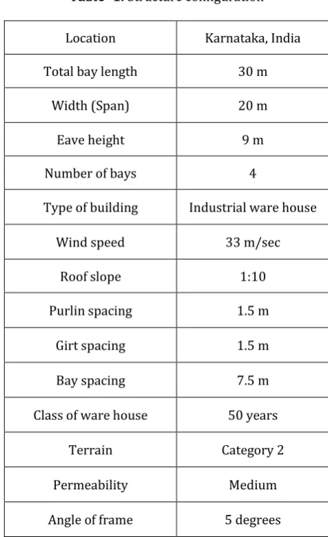
Table -1: Structure configuration
Location Karnataka, India
Total bay length 30 m
Width (Span) 20 m
Eave height 9 m
Number of bays 4
Type of building Industrial ware house
Wind speed 33 m/sec
Roof slope 1:10
Purlin spacing 1.5 m
Girt spacing 1.5 m
Bay spacing 7.5 m
Class of ware house 50 years
Terrain Category 2
Permeability Medium
Angle of frame 5 degrees
2.5
Properties of the Materials Assigned:
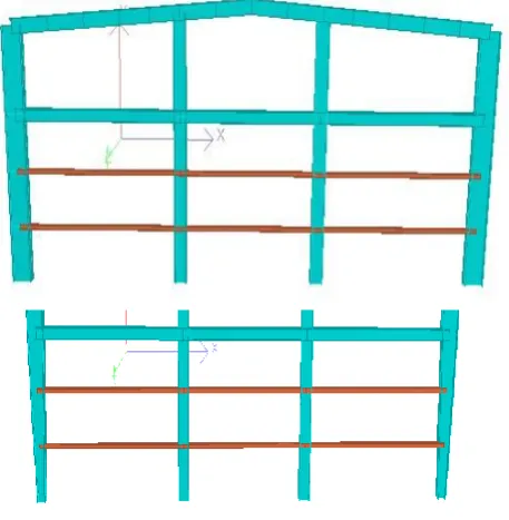
[image:3.595.51.285.379.724.2]© 2017, IRJET | Impact Factor value: 5.181 | ISO 9001:2008 Certified Journal | Page 2605 Fig -3: 3D Rectangular Section
Fig -4: 3D Tapered Section
2.6 Design Procedure as per MBMA -2002 (Metal
Building Manufacturer Codes) and AISC – 1989
(American Institute of Steel Construction Manual):
According to this codes the structural configuration of the building is considered as same as for designed with the IS – 800: 2007. Load consideration for the structure according to MBMA – 2002, ASCE-7 (American society of civil engineers) and combination of loads are taken from AISC – 1989. In this structure the design and analysis of main frames and the comparison between rectangular sections and tapered sections are carried out. The methods to design and analyse the structure is as follows.
2.7 Basic Data of the Structure:
Table-2: Data of the structure
3. RESULTS AND DISCUSSIONS
3.1 Loads and load combination details of the
structure:
The structure is designed as per the recommended codes and details of various loads and load combination are shown in the table. The loads combinations include different combinations of loads according to standard codes (IS 800 – 2007 and AISC -89/ MBMA – 2002) by considering both serviceability and strength criteria
.
3.2 Calculation of steel for the Structure (IS 800 –
2007):
Table -3: Calculation of Steel for Rectangular Sections
Description of
Members Length ( Meter ) Weight ( kg )
End Column 90 13320.12
Intermediate
Column 95 14618.23
Main Rafter 100 15386.35
Intermediate Beam 220 21069.72
Purlin 450 5535.63
Girt 160 2132.31
Total 72061.86
Table -4: Calculation of Steel for Tapered Sections
3.3 Calculation of steel for the Structure (AISC -89/
MBMA – 2002):
Table -5: Calculation of Steel for Rectangular Sections
Description of
Members Length ( Meter ) Weight ( kg )
End Column 90 13300.34
Main Rafter 100 12246.81
Beam 90 10173.61
Purlin 450 5535.62
Girt 160 2132.36
Total 40129.68
Building type Industrial ware house
Basic wind speed 33 m/s
Exposure category Exposure C (open terrain with scattered object)
Purlin spacing 1.5 m
Girt spacing 1.5 m
Bay spacing 7.5 m
Eave height 9 m
Description of
Members Length ( Meter ) Weight ( kg )
End Column 90 10784.56
Intermediate
Column 95 14618.23
Main Rafter 100 12386.35
Intermediate Beam 220 21069.72
Purlin 450 5535.61
Girt 160 2132.32
© 2017, IRJET | Impact Factor value: 5.181 | ISO 9001:2008 Certified Journal | Page 2606 Table -6: Calculation of Steel for Tapered Sections
Description of
Members Length ( Meter ) Weight ( kg )
End column 90 12200.32
Main Rafter 100 12246.84
Beam 90 10173.61
Purlin 450 5535.67
Girt 160 2132.35
Total 37129.89
[image:5.595.309.553.133.272.2]3.4 Summary of the Results from Software (IS 800 –
2007):
Table -7: Results from Software
After the analysis of the results from the software as per the Table -8, it is clear that support reaction is less for tapered sections, the deflection is more for tapered sections and the maximum shear force is more for the rectangular sections. The steel take off for the rectangle section is higher than the tapered sections.
[image:5.595.311.559.365.488.2]3.5 Summary of the Results from Software (AISC
-89/ MBMA – 2002):
Table -8: Results from Software
Description of
Results Rectangle Sections Tapered Sections
Steel Take Off (kN) 390.496 339.877
Support Reaction
(kN) 85.350 79.281
Maximum
Deflection (mm) 8.346 10.265
After the analysis of the results from the software as per the Table -8, it is clear that support reaction is less for tapered sections, the deflection is more for tapered sections and the maximum shear force is more for the rectangular sections. The steel take off is also more for rectangular sections.
3.6 Summary of the Results Comparison (IS 800 –
2007):
Fig -5: Comparison of Steel Take Off
Fig -5 represents the steel take off comparison between rectangular sections and tapered sections. It is noticed that the value of steel take off for tapered section is less compared to rectangular sections
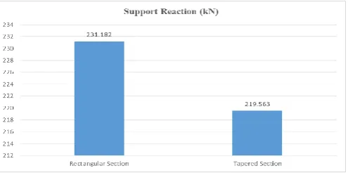
Fig -6: Comparison of Support Reaction
Fig -6 represents the Support Reaction comparison between Rectangular sections and tapered sections. It is noticed that the value of Support Reaction for tapered section is less compared to rectangular sections
Fig -7: Comparison of Maximum Deflection Description of
Results Rectangle Sections Tapered Sections Steel Take Off
(kN) 706.681 652.464
Support Reaction
(kN) 231.182 219.563
Maximum
Deflection (mm) 40.866 42.090
Maximum Shear
[image:5.595.31.277.572.665.2] [image:5.595.308.559.582.747.2]© 2017, IRJET | Impact Factor value: 5.181 | ISO 9001:2008 Certified Journal | Page 2607 Fig -7 represents the Maximum Deflection
comparison between Rectangular sections and tapered sections. It is noticed that the value of Support Reaction for tapered section is high compared to rectangular sections
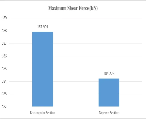
Fig -8: Comparison of Maximum Shear Force
Fig -8 represents the Maximum Shear Force comparison between Rectangular sections and tapered sections. It is noticed that the value of Support Reaction for tapered section is less compared to rectangular sections
3.7 Summary of the Results Comparison (AISC -89/
MBMA – 2002):
390.496
339.877
310 320 330 340 350 360 370 380 390 400
Rectangular Section Tapered Section
[image:6.595.305.558.58.298.2]Steel Take Off (kN)
Fig -9: Comparison of Steel Take Off
Fig -9 represents the steel take off comparison between Rectangular sections and tapered sections. It is noticed that the value of steel take off for tapered section is less compared to rectangular sections
[image:6.595.37.282.165.365.2]Fig -10: Comparison of Support Reaction
Fig -10 represents the Support Reaction comparison between Rectangular sections and tapered sections. It is noticed that the value of Support Reaction for tapered section is less compared to rectangular sections
8.346
10.265
0 2 4 6 8 10 12
Rectangular Section Tapered Section
Maximum Deflection (mm)
Fig -11: Comparison of Maximum Deflection
[image:6.595.311.551.397.566.2] [image:6.595.41.276.501.664.2]© 2017, IRJET | Impact Factor value: 5.181 | ISO 9001:2008 Certified Journal | Page 2608 Fig -12: Comparison of Maximum Shear force
Fig -12 represents the Maximum Shear Force comparison between Rectangular sections and tapered sections. It is noticed that the value of Support Reaction for tapered section is less compared to rectangular sections.
3.8 Percentage of Decrease in Weight:
8
7.9
7.84 7.86 7.88 7.9 7.92 7.94 7.96 7.98 8 8.02
IS 800: 2007 MBMA-2002/ AISC- 89
[image:7.595.40.286.416.618.2]Percentage decrease in weight
compared to rectangular sections
Fig -13: Percentage Decrease in Weight
Fig -13 represents percentage decrease of weight between tapered and rectangular sections. It is noticed that the utilisation of steel is less for tapered sections when compared to rectangular sections. The figure represents the percentage of weight decrease of the structure for both the codes.
4. CONCLUSIONS
1. Pre- engineered steel building offers the minimum cost, less time in construction, more strength, durable in the life span, flexibility in design, recyclability. In the construction of Pre-engineered steel building the basic material used for the construction is steel. It is recyclable up to infinite times. The present study is discussed about the comparison of design procedures for pre-engineered building with two different code standards are IS 800 – 2007 and MBMA – 2002/AISC -89. On the direction of current studies we can conclude that:
2. The structure is analysed and designed as per IS 800 – 2007 with two different specifications are rectangular section and tapered section, there it is noticed that the steel take off is more for rectangular section, increase in maximum support reaction and shear force but when it comes to deflection it shows more for tapered section. 3. The structure is analysed and designed as per MBMA – 2002/AISC -89with two different specifications are rectangular section and tapered section, there it is noticed that the steel take off is more for rectangular section, increase in maximum support reaction and shear force but when it comes to deflection it shows more for tapered section.
4. When the results summary of two different design procedures of the current study are compared, there is much difference appeared in steel take off, maximum deflection, maximum shear force and maximum support reaction.
5. There is increase in weight in IS 800 – 2007 compared to MBMA – 2002/AISC -89 due to “Serviceability criteria”. And also deflection limits by Indian standards are higher than deflection limits by MBMA – 2002/AISC -89.
6. Higher weight in Indian standards is mainly due to the limiting ratios of the sections (Table 2, Clauses 3.7.2 and 3.7.4).
7. The loading as per Indian codes is greater than MBMA codes that is live load is 1.08kN/m in Indian code and where as it is 0.55kN/m in MBMA.
8. It was observed in the most of the industrial projects are done with tapered sections, the reason preferring these sections it leads to an economical structural solution as compared to rectangular Sections.
5. FUTURE SCOPE
© 2017, IRJET | Impact Factor value: 5.181 | ISO 9001:2008 Certified Journal | Page 2609 time which will leads to the designer, resulting in behaviour
of the structure and economy in the construction.
REFERENCES
[1] IS: 800- 2007: General Construction in Steel – Code of Practice
[2] IS: 875 (Part 1) – 1987: code of practice for design loads (Other Than Earthquake) for buildings and structures- Dead Loads
[3] IS: 875 (Part 2) – 1987: code of practice for design loads (Other Than Earthquake) for buildings and structures- Live Loads
[4] IS: 875 (Part 3) – 1987: code of practice for design loads (Other Than Earthquake) for buildings and structures- Wind Loads
[5] IS: 456 – 2000: Plain and reinforced concrete – code of practice
[6] AISC: American Institute of Steel Construction-1989, Manual of Steel Construction, Allowable Stress Design. [7] MBMA: Metal Building Manufactures Association-2006, Metal Building Systems Manual
[8] C.M.Meera (2013), “Pre-engineered Building Design of Industrial Warehouse”,International Journal of Engineering Sciences and Emerging Technologies, Volume 5, Issue 2, pp: 75-82
[9] “Comparison of Design Procedures for Pre-engineered Building (PEB)”: A Case study, Authors: G Sai Kiran, A Kailas Rao, R. Pradeep Kumar.
[10] Dr. N. Subramanian, “Design of Steel Structures” [11] S.S.Bhavikatti, “Design of Steel Structures”
[12] Syed Firoz (2012),”Design Concept of Pre-engineered Building”, International Journal of Engineering Research and applications (IJERA), Vol.2, Issue 2,267-272
BIOGRAPHIES
Vishwanath received the B.E in Civil Engineering from Jain College of Engineering Belagavi, Karnataka, India. He is presently pursuing M.Tech in Construction Technology at Jain College of Engineering Belagavi, Karnataka, India.