Journal of Chemical and Pharmaceutical Research, 2014, 6(7):316-326
Research Article
CODEN(USA) : JCPRC5
ISSN : 0975-7384
The basic impact load model on deep water pier-ship collision
Miao Jilun
1,2*, Wang Zhaobing
2, Xiao Shengxie
11
School of Civil Engineering and Architecture, Chongqing Jiaotong University, China
2
Western Research Institute for Waterway Transportation, Chongqing Jiaotong University, China
_____________________________________________________________________________________________ABSTRACT
The collision problem between ship and bridge is a complex multidisciplinary problem. This paper states the frequently-used engineering calculation methods of the ship-bridge collision problem. After analyzing the load characteristic when the pier was impacted by the ship, the author summarizes three kinds of impact load model: triangle load model, half-wave sinusoidal load model, poly-lines load model and then gets the corresponding equations. In order to obtain the impact load characteristic value, the author builds the finite element model with various tonnage ships and bearing stations in different scales in deep water firstly. By using the impact numerical simulation method, this paper cannot only calculate the ship collision equivalent static loads, but also study the relationships between ship collision force, ship mass, tonnage and collision speed. The author can finally get the impacting force calculation formula of the ship impacts the rigid walls. Meanwhile, considering the differences between ship impacts the rigid walls and cushion cap, there is a further analysis of the effect that the cushion cap scale, shape and impact angle put on the maximum impact force and the average impact force.
Key words: Pier; ship impact; load; finite element method
_____________________________________________________________________________________________
INTRODUCTION
The collision between ship and bridge is a typical multidisciplinary problem. It relates to the bridge engineering, ship engineering, traffic engineering, collision dynamics and fluid mechanics, etc. At present, the focus of study mainly concentrates on confirmation of impact force, the damage of pier and ship, the development of anti-collide device and the probability of ship impacting bridge, etc. Many study ways of ship-bridge collision have been developed. The collision problem is a strong nonlinear problem, so the author tries analyzing the collision in details is too complex even impossible. This is the background of the simplified analysis method of ship impacting bridge[1].
author will have a further analysis on effect that the cushion cap scale, shape and collision angle put on the maximum impact force and average impact force.
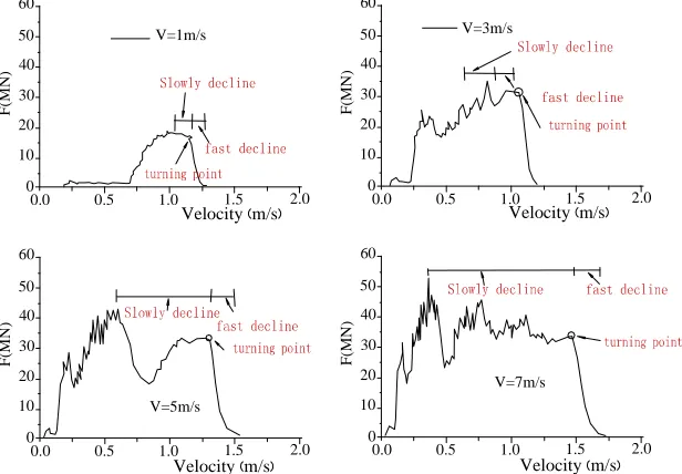
[image:2.595.153.461.272.486.2]SHIP IMPACTING DYNAMIC LOADING MODEL Time course Characteristics of impacting force
Fig. 1 displays the typical impacting force curve. By observing, people can find that the whole time course of impacting force can be divided into three stages: the ascent stage, slowly decline stage before the ship body breaking away and the quick decline stage during the breaking away period. At the beginning of impacting, there will be a short-time and small-loaded slowly ascent stage. This is explained by the fact that the previous contacting is small, so the impacting force is weak and the lasting time is relatively short. After this part of the structure is broken, there will be a wide range contacting. At this time, the impacting force will increase quickly and get to the peak.With the elastic plastic distorting of ship material and the bending, tearing and losing efficacy of structure, the ascent stage gradually declines the time slope. The loading curve will slowly decline when the enormous range of material’s plastic distorts and the structure destroyed. But this kind of global decline seems varying sometimes even the obvious platform. This decline stage increases with the impacting speed’s increase. At last, the load will incline quickly when the ship body began to break away from each other[2][3].
0.0 0.5 1.0 1.5 2.0 0
10 20 30 40 50
F
(M
N
)
60
0.0 0.5 1.0 1.5 2.0 0
10 20 30 40 50
F
(M
N
)
60
0.0 0.5 1.0 1.5 2.0 0
10 20 30 40 50
F
(M
N
)
60
0.0 0.5 1.0 1.5 2.0 0
10 20 30 40 50
F
(M
N
)
60
Velocity m/s Velocity m/s
Velocity m/s Velocity m/s
V=1m/s V=3m/s
V=5m/s
V=7m/s
Fig. 1: Characteristics of the typical impacting force changes with speed in post-peak stage
According to the time course observing of ship impacting dynamic, the author finds that the ship impacting force presenting a single peak as a whole. Although this kind of force will present the complex changes because of the differences in the ship structure and the inner structure’s crash order. According to this observing result, this paper chooses the mathematical functions as the basic loading model of dynamic design, which can not only reflect the time course’s main features of impact force, but also be convenient for the usage of engineering design. According to the characteristic curve of the ship impacting a rigid wall, the author can summarize the following impacting loading model: triangle load model, half-wave sinusoidal load model and poly-lines load model[4].
Triangle loading model
t
0 tm
t
Fm F
Time(s)
Im p ac ti n g f o rc e ( M N )
0.0 t0 0.8 tm 1.6
[image:3.595.81.508.76.222.2]0 1×10⁷ 2×10⁷ 3×10⁷ 4×10⁷ Fm
Fig. 2: Triangle loading model
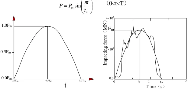
Half-wave sinusoidal loading model
Figure-3 shows the half wave sinusoidal loading mode.
t
0, as the corresponding appearing time ofP
m, is half of the lasting time of the practical impact force. There are two kinds of parameters:P
m andt
m. Following is the mathematical expression: = m m t t PP sin π (0<t<T)
4×10⁷
2×10⁷
t
Time(s)Im p ac ti n g f o rc e ( M N ) 1 2 Fm
t0 tm
[image:3.595.151.462.310.457.2]0 0.0 1.0Fm 0.5Fm 0.0Fm 1.0Tm 0.5Tm 0.0Tm
Fig. 3: Half-wave sinusoidal loading model
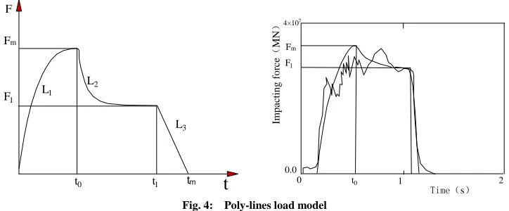
Poly-lines load model
Figure-4 shows the poly-lines loading mode. It is constituted by 3 lines:
L
1,L
2,L
3. The peak point of impact force (t
0,P
m ) is the practical curve peak. The load time before peak adoptsL
1(1/4 sine wave) as the simulation. The spherical trapezoid curve included inL
1 and timer shaft is equal to the impulse between the load zero and impacting peak.So the load zero can be calculated. L2, as the load descending stage before the e index curve breaks away which stands for the ship body. L3, is tangent to the impact force curve quickly descending stage. Load destinationt
m is the point of intersection (different from the practical one) betweenL
3 and timer shaft.L
2and
L
3’s intersection point (t
0,P ) is confirmed by the load impulse (after-peak impulse of practical curve) 1equivalent principle. There are 5 parameters belonging to poly-lines load model:Pm,P ,1
t
m,t
0,t
1. It should bepointed out is, besides superposition between peak and practical curve, poly-lines load including load origin, destination, descent fraction are all the equivalence point, which comes from the equivalence impulse.
The equation of each line:
1
L
: = t t P P m 0 2 sin π 2L
: − − − − + = 0 1 0 1
1 ( )exp
t t t t c P P P P m 3
L
: ( )1 1 1
1 t t
4×10⁷
t0 t1 tm
t
F1 Fm
F
L1
L2
L3
0 t0 1 2
Im
p
a
ct
in
g
f
o
rc
e
(
M
N
)
0.0
F1
Fm
Time(s)
Fig. 4: Poly-lines load model
Parameter c in the formula is to control the descending speed and load platform of slowly descending stageL2. When the
c is relatively small, the load descending speed is relatively slow. So there is mainly no load platform. Conversely, load descending speed is relatively quick and there is an obvious load platform afterward. A large number of impact sample time course show that: the feature of
2
L is when the load has a degree of descending, it will maintain for a
period of time at a numerical value. Then a load platform is produced and descending quickly, entering into theL . 3
By observing a plenty of sample time course, we will start from the angle of simplified load model and regard parameter c as constant 10 usually.
FEM MODEL OF CONSTRUCTION COLLISION BETWEEN SHIP AND BRIDGE The common methods of ship impacting force
The common engineering calculation methods of ship-bridge collision are Minorsk theory (V.U. Minorsk) and experienced formula[5][6][7]. Among the formulas above, the calculation results are relatively different from each other because of the constant confirmation of different calculation methods. Result of the same question and same situation shows that the calculated impact force which adopts the second method is the largest one. While the force which adopts the forth method is the smallest one.
Among the common calculating methods of ship-bridge collision, we consider some simple factors. They are mainly involves impulse formula and energy formula, etc. The result based on the experienced data has some instructing meaning to engineering applications. All the experienced formula do not completely consider the effect of the factors like specific categories, structures and materials from ship, pile foundation, cushion cap and abutment, etc. Nowadays, the global traffic infrastructure develops quickly, the river-crossing even the sea-crossing bridge are building constantly, the structure type of bridge is updating continuously and the tonnage and speed of ship are always increasing. It is harder and harder to meet the engineering design construction’s need just by calculating the traditional engineering formula.
In recent years, with the development of nonlinear limited meta-analysis technology and computer hardware system, the ship-bridge collision problem has some new breakthroughs. In terms of the different kinds of collision problem, adopting the nonlinear limited meta-technology can accurately describe the complex geometry shape, material constitutive,damages of ships and bridge. Then people can get a more accurate result. It is much better than the traditional experienced calculating formula[8][9].
Ship impacting rigid wall mode
In order to build the time course load model of ship impacting force, the author regards the rigid things as the typical collision model. After considering the effect of ship tonnage, impacting speed and angle, the author summarizes the time course load model of ship impacting force, which can be used into the structure(e.g. cushion cap) size amending when analyzes the impacted bridge so as to get the purpose of simplified analysis.
[image:4.595.125.487.74.224.2]Fig. 5: Sketch map of ship impacting rigid wall
Ship model
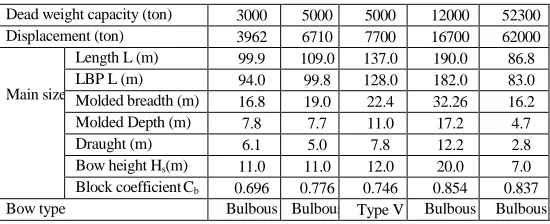
[image:5.595.170.445.252.364.2]In this paper’s simulation calculation, the basic information of the adopted ship can be seen in table-1.
Table 1: Parameter table of the shape and size of simulating ship
Dead weight capacity (ton) 3000 5000 5000 12000 52300 Displacement (ton) 3962 6710 7700 16700 62000
Main size
Length L (m) 99.9 109.0 137.0 190.0 86.8 LBP L (m) 94.0 99.8 128.0 182.0 83.0 Molded breadth (m) 16.8 19.0 22.4 32.26 16.2 Molded Depth (m) 7.8 7.7 11.0 17.2 4.7 Draught (m) 6.1 5.0 7.8 12.2 2.8 Bow height Hs(m) 11.0 11.0 12.0 20.0 7.0 Block coefficientCb 0.696 0.776 0.746 0.854 0.837
Bow type Bulbous
bow
Bulbous bow
Type V Bulbous bow
Bulbous bow
Ship impacting bridge is an unlimited impacting process. During the contacting process between bow and bridge, the bow structure will be buckled or squashed. In order to get a real impacting process, the author should simulate the shape and structure of the bow accurately. The bow part, which has the directly contact with bridge structure during the impacting process, should get an accurate simulation. Some mesh generations which is far away from the impacting area are relatively thick and can be replaced by steel. The rolled steel strain rate effect and fracture effect also should be considered into the impacting calculation.
The nose of ship is steel structure and it can be disposed into elastic plastic material. The linear mode should be used and the elasticity modulus is 2.1×10⁵MPa. The Poisson’s ratio is 0.3. Yield strength is 235MPa. Harden modulus is 2.1×10²MPa. Invalid strain is 0.35. In order to consider the effect that the material yield strength got from the strain rate, the author uses Cowper-Symonds mode in materials, C=40.4, P=5.0. The friction coefficient 0.3 is considered into the calculation process[10].
The pile foundation is composed by cushion cap and pile. The cushion caps are mostly rectangle, polygon and polygon with arc. The edges are mostly straight flange or arc in the cushion cap which is vertical to the bridge axes direction. This paper considers the cushion cap mainly rectangle and rotundity. The others are mostly composed by these two shapes. As the maximum ship impacting force is the key to engineering design, considering the impacting force, the author can ignore the effect that rigidity makes to impacting force. So cushion cap’s spatial position is fixed as a complete rigidity. The figure 6. shows the limited model of bridge members.
(a) Rectangle (b) Rotundity
Fig. 6: Cushion cap finite element model
EQUIVALENT STATIC LOAD MODEL Definition of equivalent static load model
appears in some time during the impacting process. In the engineering design, such a dynamic impacting process equaling to a static load is needed. Regarding the equivalent load as the whole dynamic process, people should choose a proper way to define the equivalent static load. The author chooses two ways to define it, seeing figure-7. The first way is to choose the peak
P
m of the whole time and process. The second way is to choose the population meanP
g of impacting force in time domain.Time(s)
Im
p
a
ct
in
g
f
o
rc
e
(
M
N
)
[image:6.595.195.419.152.322.2]Peak
Fig. 7: Definition of equivalent impacting load
Fig.7 is an example of ship impacting force numerical value simulation structure. The beginning time of impacting is
t
g0. The end time ist
g. The whole lasting time of impacting is∆
t
g. If the impulse isI
g during ∆tg time period, the whole average impacting force isg g
g I t
P = /∆ .
The Fundamental Formula of Equivalent Static Impact Load
Impacting force has been influenced by many factors. When the other factors are relatively fixed, the impacting speed has remarkable influence on impacting force. From the perspective of impacting mechanics, the faster the speed, the stronger the force is and the corresponding duration time is long. In order to clearly reflect the influence of speed on force, the passage has used the finite element model established in the third segment to do simulative calculation of the process ships colliding rigid wall.
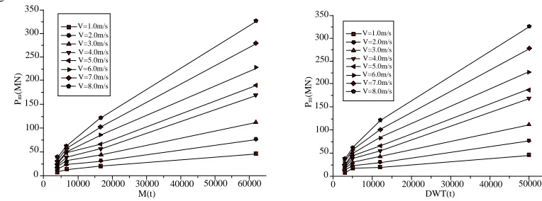
Figure 8 has shown how the equivalent static impact load of ships with various weights changed with the change of speed. From the figure, we can see that the equivalent static impact load is increased with the increase of speed. They basically grow in linear relationship. So the straight line equation y=A+Bx can be used for matching.
0 1 2 3 4 5 6 7 8 9
Velocity V(m/s)
Pm
(M
N
)
P=-1.8615+40.053*V
0
[image:6.595.213.402.541.685.2]40 80 120 160 200 240 280 320 360
Fig. 8: Relation curve of 50000DWT ship ~V
increasing.
0 10000 20000 30000 40000 50000 60000
M(t) 0
50 100 150 200 250 300 350
P
m
(M
N
)
V=1.0m/s V=2.0m/s V=3.0m/s V=4.0m/s V=5.0m/s V=6.0m/s V=7.0m/s V=8.0m/s
0 10000 20000 30000 40000 50000
DWT(t) 0
50 100 150 200 250 300 350
Pm
(M
N
)
[image:7.595.108.490.82.224.2]V=1.0m/s V=2.0m/s V=3.0m/s V=4.0m/s V=5.0m/s V=6.0m/s V=7.0m/s V=8.0m/s
Fig. 9: Relationship between the Maximum Impacting Force and M (up) Fig. 10: Relationship between the Maximum Impacting Force and DWT (bottom)
As the relationship between maximum impacting force and the mass of ship is not in linear line and its increasing trend conforms to the law of power function, so we can use the form of power function to match. Here we choose
b
ax
y
=
.The matching can be implemented in two steps. First, matchP
m in various speed with M or DWT and we can get coefficient a and index b in various speed. Then match the first step to get index b. Averaging them and we can get the averageb
.then, makeb
as a fixed index and match again theP
m in various speed with M or DWT. Thuswe can acquire a series of new coefficient a corresponding to the fixed index
b
.Through the above matching and simplification, the relationship of maximum impacting power with mass and speed can be shown as:
V M Pm=0.017 0.7
Maximum impacting force with the ship’s mass and speed can be shown as:
V DWT Pm=0.031( )0..66
In the formula:
P
m is the maximum impacting force ships colliding with rigid wall; M is the total mass of ships (ton);DWT is the load tonnage of ships (ton);V is the impacting speed (m/s).With the same method, we can get the relationship between the overall average impacting force and ship mass or tonnage:
66 .. 0
) 0062 . 0 01 . 0
( V M
Pg = +
64 .. 0
) )( 0117 . 0 016 . 0
( V DWT
Pg= +
In the formula,
P
g is the overall average impacting force ships colliding with rigid wall (MN).The Correction of Impacting Angle
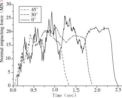
45° 30° 0°
N
o
rm
al
i
m
p
ac
ti
n
g
f
o
rc
e
(
M
N
Time(sec)
0.0 0.5 1.0 2.0 2.5
[image:8.595.205.408.72.235.2]0 5 10 15 20 25 30
Fig. 11: Normal impacting time course of each angle
By the above 12000 DWT ships colliding the cushion cap obliquely, the influence of impacting angle on impacting force has been analyzed qualitatively. To further acquire the mathematic relation between impacting force and impacting angle, the situation of ships with different tonnages colliding obliquely has been calculated.
By counting and analyzing the result, the correction coefficient of oblique maximum impacting can be shown as:
(
θ)
α
γ 1 1 1 cos
0
0 −
− =
b M
DWT
In the formula,
a
0 andb
0 are simulation parameters. As for normal impacting force,a
0=28.64 ,0
b
=0.40. Therelationship of
γ
g andγ
M, the oblique impacting correction coefficients of overall average impacting force, isM g
g
c
γ
γ
=
⋅
,c
gis 0.64.The amending coefficient of impacted geometry
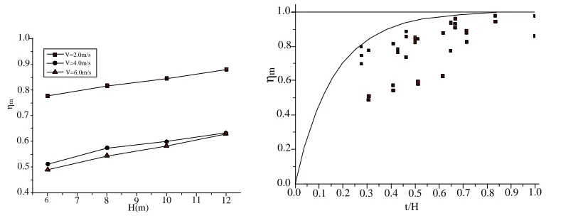
Generally speaking, bow’s force of impacting the rigid wall is bigger than the force, which owns smaller ship thickness than the body height. In order to reflect the effect what the ship-impacting get from impacted rectangle geometry thickness, the paper need to introduce the amending coefficient:
m tm m=P /P
η
,g tg g =P /P
η
tm
P
, is the maximum impacting force andP
tg is the total average impacting force of the ship-impacting force.V=2.0m/s V=4.0m/s V=6.0m/s η m H(m)
6 7 8 9 10 11 12
0.4 0.5 0.6 0.7 0.8 0.9 1.0 η m t/H
[image:9.595.114.524.70.227.2]0.0 0.1 0.2 0.3 0.4 0.5 0.6 0.7 0.8 0.9 1.0 0.0 0.2 0.4 0.6 0.8 1.0
[image:9.595.238.370.573.631.2]Fig 12: Relation of
η
m with H for ship 50000DWT (left)Fig 13: Correction coefficient of
P
mfor rectangle geometry (right)Considering the dispersing of impacting force amending coefficient, it is hard to get a unified function expression by using parameter statistic to calculate the 3000DWT~50000DWT impacting amending coefficient. The
m
η
in each tonnage will increase as the increase of cushion cap thickness. When the thickness increases to a number (bow height),m
η
will keep constant if it is 1. From the bridge anti-impacting design angle, the author finds that is harmful to the engineering safety if theη
m is small enough. But it is conservation to ignore the effect. Considering the factors above,η
m can be gotten from the envelope of different force correction coefficient, which can be seen in figure 13. Horizontal axis in the figure is the ratio between impacted geometry thickness t and the bow height Hs. Drawing all kinds of amending coefficients in each calculating condition in the figure, the author can get the function expression which the outer envelope is index 1: ≥ < − − = 0 . 1 1 0 . 1 6 exp 1 s s s m H t H t H t η m
η
, is the rectangle geometry amending coefficient of maximum force. t, is the thickness of cushion cap(m).H
s, is the bow height.In terms of total average impacting force, the amending coefficient
η
g is: ≥ < − − = 0 . 1 1 0 . 1 7 . 4 exp 1 s s s g H t H t H t η
Similar to the discussion of rectangle geometry, the author can also get the amending coefficient of rotundity geometry:
068 . 0 8 . 0 R m =
ξ
08 . 0 596 . 0 R g =ξ
R is the radius of cushion cap round geometry in the formula.
Calculation formula of equivalent static ship-impacting force
static ship-impacting force.
1) Calculation formula of maximum ship-impacting force
V M Pm = ⋅ m⋅ m⋅ m⋅ ⋅
7 . 0
017 .
0 η γ ξ
V DWT Pm=0.031⋅ηm⋅γm⋅ξm⋅( )0.66⋅
2) Calculation formula of total average ship-impacting force
(
)
0.660062 . 0 01 .
0 V M
Pg=
η
g⋅γ
g⋅ξ
g⋅ + ⋅(
)
0.64) ( 0117 . 0 016 .
0 V DWT
Pg =
η
g⋅γ
g⋅ξ
g⋅ + ⋅CONCLUSION
Based on a plenty of impacting force time course sample, this paper summarized and put forward three kinds of impacting force time course load model. These three kinds of simplified basic dynamic modes are all based on the impulse equality, which in order to guarantee the impulse as main feature during the impulse process. Half-wave sinusoidal load mode owns the features like simple style. The other feature is it can reflect the main dynamic characters of ship impacting load. Poly-lines load model based on the original force’s time-developing character, adopting the percentage of impulse and time as each stage’s control standard. From this paper’s simplified result the author can find that the coefficient in modes all can show the function of original impacting speed V, which simplifies the difficulty of getting the confirmed parameter.
Regarding the impact force time course as the load input can overcome the shortcoming: static calculation method of impact force cannot consider the structure quality inertia restrain of the body above impacted part. Such a restrain inner reflection to the upper structure of impacted part should not be ignored. Comparing with the practical impact calculation force load, the poly-lines load mode’s error is relatively small among the three kinds of modes. The whole error is smaller than 35%. Meanwhile, the frequency feature of its structure reflection is similar to the practical one.
By using the simulating analysis to conduct a detailed simulating calculation, which is aiming at a series tonnage ship impacting rigid wall with all kinds of speed, the author studies the relationship between force, ship mass, tonnage and impacting speed. At last, the paper gets the force calculation formula of ship impacting rigid wall in deep water. Meanwhile, considering the differences between ship impacting rigid wall and bearing station, the paper makes a further analysis on the effect, which is the force effect from the cushion cap, shape, and impacting angle. The author also gets the practical calculation method which is the factors to ship impacting amending. On this basis, the author puts forward the simplified calculation formula.
The study of this paper provides a basic thinking and load mode for building the bridge-ship impacting design method. There are also some complex factors needed to be studied and developed, such as the effect between bridge member geometrical shape and size, the random factor of ship inner structure and impacting angle. The related mode parameter also needs our constant accumulation and development. Building such a bridge-ship impacting force design theory need a long and persistent study and experienced process. This is just a beginning.
Acknowledgments
This research was supported by China Postdoctoral Science Foundation(Grant No. 2014M552538XB), Chongqing science & technology commission fund(Grant No. cstc2014jcyjA30021), the open fund of national engineering technology research center for inland waterway regulation, and Key laboratory of hydraulic and waterway engineering, ministry of Education, Chongqing Jiaotong University(Grant No. SLK2014B04).
REFERENCES
[1] Wu Jing, Journal of Guangdong communication polytechnic,2014,12(4),60-64.
[2] Lenselink.etc, Proceedings of the second international of shore and polar engineering conference,1992. [3] Vredeveldt A.W. etc.Full scale ship collision tests, Third international symposium on structural crash
worthiness and failure,1993.
[4] Wang Junjie, Meng Dewei, Ou Bifeng. Journal of vibration and shock.2010,29(11),165-170.
[5] AASHTO. LRFD bridge design specification and commentary, American association of state highway and
transportation officials, Washington D. C, 2004.
[7] AASHTO,Guide specification and commentary for vessel collision design of highway bridges,2009. [8] Gary R.Consolazio,David R.Cowan. Computers and Structures,2003,81,547-557. [9] Petersen P. T, Zhang S. On impact mechanics in ship collision. Marine structure,1998,11(10),42-49.
[10] Wang Junjie,Yan Haiquan,Qian Hua. Journal of highway and transportation research and development.