International Journal of Emerging Technology and Advanced Engineering
Website: www.ijetae.com (ISSN 2250-2459,ISO 9001:2008 Certified Journal, Volume 3, Issue 8, August 2013)
731
Design, Development of Six Phase Squirrel Cage Induction
Motor and its Comparative Analysis with Equivalent Three
Phase Squirrel Cage Induction Motor Using Circle Diagram
Dr. Archana Nanoty
1, Dr. A.R.Chudasama
21Principal, Dr.Jivraj Mehta Institute of Technology, Mogar, Anand,Gujarat 2Director, Neotech Engineering College, Vadodara,Gujarat
Abstract—For machine drive applications, multiphase induction motor could potentially meet the demand for high power electric drive systems which are both rugged and energy efficient. High phase number drives possess several advantages over conventional three phase drives such as high torque, higher reliability and increased power. Multiphase induction motors have found many applications such as electric/hybrid vehicles, aerospace applications, ship propulsion etc.This paper focuses on design, development of prototype six phase induction motor carried out at M/sJyoti Ltd,.Mogar, Anand, Gujarat and then comparison with equivalent three phase induction motor using Circle diagram is shown.
Keywords—six phase Induction motor design and development, Circle Diagram, Torque comparison
I. INTRODUCTION
Amongst many types of electrical motors, induction motors still enjoy the same popularity as they did a century ago. Several factors which include robustness, low cost and low maintenance have made them popular for industrial applications when compared to dc and other ac motors. Another aspect in induction motor drives which has been researched recently is the use of multiphase induction motors where the number of stator phases is more than three.
Here, a multi-phase system is a system with more than three stator phases. Among the different multi-phase induction motor drives being researched, following important advantage for the dual-3-phase induction motor having two stator winding sets spatially shifted by 30 electrical degrees with separated neutral is: The dual-3-phase solution can generate higher torque as compared to conventional three phase motor. This characteristic makes them convenient in high power and/or high current applications, such as ship propulsion, aerospace applications, and electric / hybrid vehicles (EV). [5]
Output Torque of multiphase induction motors is much higher than that of conventional three phase Induction Motor. Emil Levi [1] provides a review of the recent developments in the area of multiphase induction motor control. In this paper Vector control and direct torque control (DTC) are addressed and utilization of the additional degrees of freedom that exist in multiphase machines for differing purposes is described (higher stator current harmonic injection for torque enhancement and control of a group of series-connected multiphase motors supplied from a single multiphase VSI).
II. BRIEF CONSTRUCTIONAL DETAILS OF INDUCTION MOTOR
A poly phase induction motor consists essentially of two major parts, the stator and the rotor. The construction of each one is basically a laminated core provided with slots which house windings. When one of the windings is exited with AC voltage, a rotating field is set up. This field produces an emf (Electromotive Force) in the other winding by transformer action which in turn circulates current in the later if it is short circuited. The currents flowing in the second winding interact with the field produced by the first winding thereby producing a torque which is responsible for the rotation of the rotor.
Basically a three phase Induction motor consists of stator and rotor. The Induction motor is invented by Great scientist Nikol Tesla.
International Journal of Emerging Technology and Advanced Engineering
Website: www.ijetae.com (ISSN 2250-2459,ISO 9001:2008 Certified Journal, Volume 3, Issue 8, August 2013)
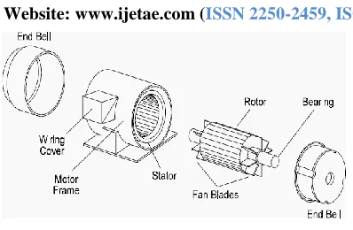
[image:2.612.70.269.117.247.2]732 Figure 1: Assembly of a typical three phase induction motor
As with the stator, the rotor consists of a set of slotted steel laminations pressed together in the form of a cylindrical magnetic path and the electrical circuit. There are two types of motor rotors: The wound rotor and Squirrel cage rotor. Because of the ease of winding, Squirrel cage induction motor is designed.
III. ACTUAL DESIGN OF PROTOTYPE SIX PHASE INDUCTION MOTOR
To begin with, an m-phase symmetrical induction machine, such that the spatial displacement between any two consecutive stator phases equals α = 2π/m, is considered. Stator winding is treated as m–phase and it is assumed that the windings are sinusoidally distributed, so that all higher spatial harmonics of the magneto-motive force can be neglected. The phase number m can be either odd or even.
When the number of phases is six, i.e. m = 6, there are two, three phase windings. The two, three phase windings are displaced by 600 in symmetrical design but there is a problem of magnetic circulating currents.
So asymmetrical design is implemented in which two, three phase windings are displaced by 300, which eliminates (6n + 1) order harmonics, where n = 1,3,5………. [1].
A six phase machine can be easily constructed by splitting the 600 phase belt into two portions each spanning 300.The winding distribution factor increases from 0.965 for three phase to 1.0 for six phase for split phase belt connection.[8] A true six phase that retains the same winding pitch and distribution factor is shown in the table1 below.
Table1
Multiphase Winding configuration
The six-phase machine uses the same magnetic frame with the baseline machine. So initially the stator dimensions, stator size, rotor size etc. were kept same as 3 phase, 3 HP induction motor. And the same stator is rewound for making six phase.
Stator design depends upon number of stator slots.The emfs induced in coil sides placed in neighboring slots are thus phase shifted by an angle, αes, expressible in electrical radians as follows:
αes = πp / Ss [1]
General expression for number of stator slots is given by,
Ss = m/2.p [2+K] Slots [2]
Where, Ss = No. of Stator Slots
m = No. of machine phases
p = No. of machine poles
K = 0,1,2…..
For Symmetrical ac winding: K = 0,2,4…..
For Asymmetrical ac winding: K = 1,3,5….
In our case no. of poles = 4, so putting the values of m, p, K in equation [2] we get,
International Journal of Emerging Technology and Advanced Engineering
Website: www.ijetae.com (ISSN 2250-2459,ISO 9001:2008 Certified Journal, Volume 3, Issue 8, August 2013)
733 Thus we have a 4-pole machine with 36 stator slots. In order to keep the leakage distribution balanced, the phases are displaced among the two stator layers. The six-phases are constructed such that one three-phase group is displaced from the other one by 30 electrical degrees.
Thus we have an asymmetrical six phase machine, where
θm = 2. θe / p [4] θm = 2 .30° / 4 = 15° mechanical [5]
Slot pitch = 360° / 36 = 10° mechanical [6]
Hence, the 30 electrical degrees displacement corresponds to 15°/10° = 1.5 slots.
We cannot implement such a configuration and have to use an approximation. This is done as shown below :
One of the three-phase groups has the same structure of the baseline machine with half of the circuits and winding distributed in 3 slots per pole per phase
(qA = 3)
The second group is distributed into 4 slots per pole per phase (qX = 4) but keeping the same number of conductors per pole per phase.
Initially we have used same dimensions as per 3 phase, 3 HP, induction motor at a manufacturing unit. And stator is divided into two parts and winding is carried out as discussed above.
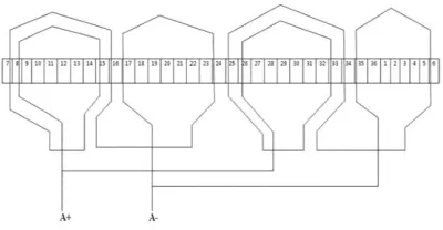
Prototype six phase induction motor is developed in such a way that, first three phase set say, “ABC” has two pole pitches viz. 9 for outer layer and 7 for inner layer. While the second three phase set say “XYZ” has two pole pitches viz.8 for outer layer and 6 for inner layer. The number of poles is kept same for both the windings. Also wire gauge and number of turns are same for both the windings. The neutrals of two three phase sets are kept open. The motor is star connected.
[image:3.612.70.270.575.679.2]Figure 2. Phase A-Winding Layout
Figure 3. Phase X-Winding Layout
IV. CALCULATIONS OF PROTOTYPE SIX PHASE INDUCTION MOTOR
To design main dimensions of 3 HP (2.238 KW), 200 Volts, 6phase, 4 pole induction motor (assuming efficiency η= 85%, power factor cosΦ = 0.8 lagging
Q = Output in KW / η x cosΦ [7]
Q = 2.238 / 0.85 x 0.8 = 3.3 KVA [8]
Also Q = C0 D2 Lns [9]
And C0 = 11 Bav ac Kw 10-3 [10]
Kw = Window space factor for 6 phase = 1
Assuming Specific magnetic loadings Bav = 0.65 wb/m2 , Specific electric loading, ac = 12000 Ampere conductors
C0 = 11 x 0.65 x 12000 x 1 x 10-3 = 85.8 [11]
Putting the value of C0 from [10] in [8]
We get, D = 0.125 m = 125 mm [12]
Taking overall good design condition, i.e. L / Γ [13]
Where, Γ = pole pitch = π D / p [14]
Thus L = 0.1 m = 100 mm [15]
Similarly turns per phase,
Tph = Eph / 4.44 fφ Kw = 312 [16]
Total conductors = Zss = 2mTph [17]
Stator slots Ss =36, no. of phases m =6
Thus Total conductors = 3744
Conductors per slot Zs = Zss / Ss = 3744 / 36 =104 [18]
International Journal of Emerging Technology and Advanced Engineering
Website: www.ijetae.com (ISSN 2250-2459,ISO 9001:2008 Certified Journal, Volume 3, Issue 8, August 2013)
734 Stator Dimensions:-
Stator Bore or Inner Diameter =125 mm
Stator Slots = 36
Stack length = 100 mm
Rotor Dimensions:-
Outer Diameter =125 mm
Rotor Slots = 28
Stack length = 100 mm
Conductor size :- 22 SWG
Conductors per slot = 104
No. of Turns per phase = 312
Insulation :- Class F
V. ACTUAL DEVELOPMENT OF PROTOTYPE SIX PHASE INDUCTION MOTOR
1. Initially a stator lamination having diameter 125 mm is pressed into a cylindrical frame as per the stack length of 110 mm. Rotor laminations as per the dimension are also pressed for 28 rotor slots.
2. Then windings are formed as per the number of turns per phase shown in the figure 2 and 3.
3. 22 SWG Copper conductors is used for winding.
Class F insulation is used
Photograph1. Actual winding of six phase prototype IM
Photograph2. Six phase Induction Motor
Before supplying the motor from two, three phase inverters, the no load and blocked rotor tests are carried out with two, three phase sets shorted. The six phase motor is supplied through three phase, 200 V, 50 Hz supply when A shorted to X, B to Y, C to Z. the same set up is supplied through single three phase inverter for variable frequency operation.
Photograph3: ABC and XYZ shorted and connected to Dynamo as a load
No Load test results when ABC and XYZ shorted: (Six phase star connected 3 HP, 4 pole IM)
No Load voltage, V0 = 200 V
No Load Current, I0 = 4.19 A
No Load Speed N = 1475 rpm
International Journal of Emerging Technology and Advanced Engineering
Website: www.ijetae.com (ISSN 2250-2459,ISO 9001:2008 Certified Journal, Volume 3, Issue 8, August 2013)
735 In general,
W = mVph Iph Cos Φ [19]
For three phase IM, m=3
W = 3 Vph Iph Cos Φ = √3 VL IL Cos Φ [20]
For six phase IM, m= 6
W = 6 Vph Iph Cos Φ = 2√3 VL ILCos Φ [21]
W0 = 2 √3 V0 I0 Cos Φ0 [22]
Φ0 = W0 / 2√3 V0 I0 = 82.87o [23]
Blocked rotor test results
Vsc = 64 V
Isc = 9.44 A
Wsc = 0.56 Kw
Speed N = 1460 rpm
Wsc = 2 √3 Vsc Isc Cos Φsc [24]
Φsc = Wsc / 2 √3 Vsc Isc [25] Φsc = 74.47
o
With this knowledge, the circle diagrams for three phase, 3 HP and six phase, 3 HP (shown in figure 4 and figure 5 respectively) are drawn to calculate torque and efficiency, etc.
[image:5.612.327.561.159.411.2]For three phase, 3 HP, 4 pole, 200V induction motor, choosing the scale of 1cm = 1 Amp the circle diagram as shown in the figure 3.33 is drawn. Power scale is 1 cm =340 Watt (Power scale: √3 x voltage)
Figure 4. Circle Diagram for three phase 3 HP, 200V, 4 pole IM
Full Load line current OP = 8.4 cm
As per current scale, 1 cm = 1 Amp
Hence full load current = 8.4 Amp
Full load CosΦ = PT / OP = 6.8 / 8.4 = 0.8 lag [26]
Full load torque = Rotor input = PR = 5 cm
As per power scale 1 cm = 340 W
Hence
full load torque = 5 x 340 = 1700 Synchronous watts [27]
Full Load Efficiency = PQ / PT = 4.5/6.8 = 66 % [28]
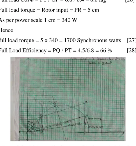
Figure5. Circle Diagram for six phase 3HP, 200v, 4 pole Induction motor
For six phase, 3 HP, 4 pole, 200 Volts Induction motor the current scale is
1 cm = 2 Amp and power scale is 1 cm = 695 W, (2√3 x voltage)
From figure 5,
Full Load line current OP = 5 cm
As per current scale 1 cm = 2 Amp
Hence Full load line current = 10 Amp
Full Load P.f. CosΦ = PT/ OP = 4/5 = 0.8 [29]
Full Load torque = Rotor input = PR = 3.9 cm [30]
As per power scale 1 cm = 695 W
Hence
Full load torque = 3.9 x 695
= 2710.5 Synchronous Watts [31]
Full Load Efficiency = PQ / PT
International Journal of Emerging Technology and Advanced Engineering
Website: www.ijetae.com (ISSN 2250-2459,ISO 9001:2008 Certified Journal, Volume 3, Issue 8, August 2013)
736 VI. DISCUSSION
From equations [27] and [31]
The full load torque of 3 HP, 4 pole, 200 volts, 3 phase induction motor is 1700 synchronous Watts and full load torque of 3 HP, 4 pole, 200 volts, 6 phase induction motor is 2710.5 Synchronous Watts.
Thus
Full Load torque of 6 phase IM / Full Load torque of 3 phase IM = 2710.5/1700 = 1.6.
Also efficiency of 6 phase IM = 88% ; From equation [32]
While efficiency of 3 phase IM = 66%; From equation [28]
From the circle diagram and calculations it is clear that the torque of six phase induction motor is more and found to be approximately 1.6 times more than equivalent three phase motor. Also Efficiency of six phase induction motor is 1.4 times more than that of equivalent three phase induction motor.The torque of six phase induction motor is much higher than equivalent three phase induction motor. Prototype six phase induction motor torque is 1.6 times that of equivalent three phase motor.
In [1]-[6] torque improvement is obtained by third harmonic current injection. Third harmonic current injection needs large inductors. The application of multiphase induction motor is mainly in high power-high current applications so the use of inductor for current injection is uneconomical.
Though the initial cost of six phase induction motor is increased as compared to three phase induction motor but at the same time efficiency and torque are significantly improved. Also torque improvement with third harmonic current injection is 1.4 times that of equivalent three phase induction motor [1]-[6] while the developed prototype six phase induction motor torque is 1.6 times that of equivalent three phase induction motor. As the motor rating increases it is tedious to arrange third harmonic current.
1. Same design can be extended in multiples of three, e.g. for 9 phase there will be three sets of three phase windings with 200 phase shift.
2. The design is applicable for even phase number only. 3. Looking to the area of application i.e. high
power-high current application though the initial cost is higher than that of equivalent three phase but efficiency and torque are much higher.
4. From the no load and load tests conducted separately on ABC and XYZ, it is obvious that the prototype motor is highly reliable: If one of the three phase sets is not supplied the motor will continue to run as three phase and continuity of operation is maintained as the neutrals are separate.
5. Instead of copper conductors, aluminum conductors may be used to reduce the cost, thus making it more economical.
REFERENCES
[1] Emil Levi, “Recent Developments in High Performance Variable-Speed Multiphase Induction Motor Drives” Sixth International Symposium Nikola Tesla, Belgrade, Serbia. 18th – 20th October, 2006.
[2] Robert H. Nelson, Thomas A. Lipo, and Paul C. Krause, “Stability Analysis of a Symmetrical Induction Machine” IEEE Transactions on Power Apparatus and Systems, Vol. 88, No. 1, November 1969. [3] L. Romeral, “Motion Control for Electric Drives” XVI Journal of
Conference in Electronics Engineering, JCEE-2002, Terrasa, Spain, pp 26-30. November 2002.
[4] Samir Hamdani, Omar Touhami, Rachid Ibtiouen, “ A Generalized Two Axes Model of a squirrel-Cage Induction Motor for rotor Fault Diagnosis” Serbian Journal Of Electrical Engineering Vol. 5, No. 1, 155-170. May 2008.
[5] K. Gopalkumar, Mahopatra, “A novel scheme for six phase induction motor with open end windings.” 28th
Annual Conference of IEEE Industrial Electronics Society, Spain. 5th - 8th November,
2002.
[6] Renato O. C. Lyra, Thomas A. Lipo, “Torque Density Improvement in a Six-Phase Induction Motor With Third Harmonic Current Injection” IEEE Transactions on Industry Applications, Vol. 38, no. 5, pp. 1351-1360, September – October, 2002.
[7] G. K. Singh, S. K. Lim, “A Simple Indirect Field-oriented Control Scheme for Multiphase Induction Machine”, IEEE Transactions on Industrial Electronics, Vol. 52, No. 4, August 2005
[8] G. K. Singh, “Multiphase Induction Machine drive research”, Elsevier Journal, Electric Power System Research, Vol. 61, pp. 139-147, 2002.
Acknowledgement:
Authors are indebted to Dr. K.K. Thakkar, Director, M/S Jyoti Ltd, Mogar, Anand, Gujarat for providing all facilities to carry out research work.
APPENDIX-I
No Load and Blocked rotor tests were carried out one by one on ABC and XYZ terminals, the readings obtained were same for both ABC and XYZ.
International Journal of Emerging Technology and Advanced Engineering
Website: www.ijetae.com (ISSN 2250-2459,ISO 9001:2008 Certified Journal, Volume 3, Issue 8, August 2013)
737 Sr.
No.
TABLE-I NO LOAD TEST RESULTS FOR THREE PHASE 3 HP, 200V IM
Supply Voltage (Volts)
Current (Amps)
Speed (RPM)
1 200 2.33 1492
Sr. No.
TABLE-II LOAD TEST RESULTS FOR THREE PHASE 3 HP, 200V IM
Supply Voltage (Volts)
Current (Amps)
Speed (RPM)