Comparison of Cooling Load Calculations by E20 and
HAP Software
Fahad AlHarbi*, Abdullah AlRomaih, Sulaiman AlHudaithi, Abdullah AlHusayyani, Talal AlQadhi,
Ali Sulaiman Alsagri, Abdul Rahman Alateyah, M. Shameer Basha
Department of Mechanical Engineering, Qassim University, Saudi Arabia
Received July 24, 2019; Revised September 9, 2019; Accepted September 23, 2019
Copyright©2019 by authors, all rights reserved. Authors agree that this article remains permanently open access under the terms of the Creative Commons Attribution License 4.0 International License
Abstract
A complete air conditioning system has been developed to control ambient conditions such as temperature, relative humidity, air movement, etc. in an economical manner for AlFahad Mosque located Unaizah in qassim region K.S.A. In this paper, the calculations were carried out taking into account the ASHRAE standards. For space references and calculations, the plan is developed by AUTO CAD. After taking the plan investigated the location and materials used for construction, based on the study theoretical thermal load calculations were performed by the E20 Method for number of rooms as per the plan and summarizing. The present plan has one huge room of each floor. Based on the heat load calculations, cfm values were found for number rooms and summarized for entire building. Obtained the cfm for first floor as one room and ground floor as one room and add for total cfm for the AlFahad mosque. The object of the paper is about the cooling load calculation for the AlFahad Mosque at Unaizah Qassim Region Saudi Arabi (K.S.A.). The load calculation is carried out by using E20 Manually and HAP software. Nowadays, people are estimating the load calculation by approximation method i.e. by giving dimensions of building which the sellers are estimating roughly tonnage of refrigeration (market method or ALGhaith company method). These cooling load calculations obtained, which is under or over the comfort condition. To overcome this problem, the cooling load calculated by E20 manual method, HAP software and compared.Keywords
ASHRAE Handbook, HVAC, E20, Auto CAD, HAP Software1. Introduction
1.1. Thermal Ventilation and Air Conditioning
The air conditioning is used in most commercial real estate, from small shops and cafes to high-rise buildings and auditorium. In order to meet these various applications, the air conditioning systems have different heating and cooling capacities and have a variety of superstructures and layouts.
Many of our homes, offices and commercial facilities would not be left without control of the indoor environment. The "luxury label", which has been tied to the air conditioning system in previous decades, has given it a practical value when it comes to making our lives healthier and more comfort.
AutoCAD is the software for mechanical, electrical and plumbing designers. Building and coordinating building documents is more efficient with AutoCAD design tools. AutoCAD also assesses our vision and improves our efficiency through our specially developed software for MEP designers.
1.2. History of HVAC
In 1902, a 25-year-old engineer from New York, named Willis Carrier, invented the first modern air conditioning system. However, the machine which sends air through water-cooled coils was not directed to human comfort. It was designed to control the humidity in the printing shop where he worked.
Heating, ventilation and air conditioning (HVAC) is the technology of indoor and vehicle comfort. Its aim is to provide thermal comfort and acceptable indoor air quality.
Air conditioners use Refrigerants that can easily turn from a gas into a liquid and return. This Refrigerant is used to transfer heat from the air within a house to the outside air. The machine has three main parts. They are compressor, condenser and evaporator.
HVAC (Heating, ventilation and air-conditioning) system is not only heats but also cools residential, commercial or industrial buildings. The HVAC system may also be responsible for the provision of fresh outdoor air to dilute internal airborne substances such as odors from occupants, volatile organic compounds (VOCs) emitted from interior equipment, chemicals used for cleaning, and so on properly designed system will provide a comfortable indoor life environment all year round, if properly maintained.
1.3. Working of Ac
An air conditioning unit cools and dehumidifies the air as it passes over a cold coil surface. The inner coil is an air-to-liquid heat exchanger with rows of pipes that guide the liquid through the coil. Ribbed surfaces connected to these tubes increase the total area of the cold surface thereby increasing the heat transfer characteristics between the air flowing through the coil and the liquid flowing through the coil. The type of liquid used depends on the selected system. Direct-expansion (DX) equipment uses refrigerant as a liquid medium. Cooling water (CW) can also be used as a liquid medium. If the required temperature of a cold water system is close to the freezing point of the water, a freezer in the form of glycols or salts is added. Irrespective of the liquid medium used, the liquid is fed to the cooling coil at a cold temperature.
The first modern electric air conditioner was invented by Willis Carrier [14] in 1902 in Buffalo, New York. After completing Cornell University, Carrier found a job at the Buffalo Forge Company.
In the case of direct expansion units, the air which passes through the internal cooling coil heats the cold liquid refrigerant. The heating of the refrigerant leads to boiling and converts the refrigerant from a cold liquid into a warm gas. This warm gas (or steam) is pumped from the cooling coil to the compressor through a copper pipe (suction line to the compressor), where the warm gas is compressed. In some cases, an accumulator is placed between the cooling coil and the compressor to detect unused liquid refrigerant and ensures that only steam enters the compressor. The compression process increases the pressure of the refrigerant vapor and considerably increases the temperature of the steam. The compressor pumps the steam through a further heat exchanger (outside condenser), where heat is rejected and the hot gas is condensed to a warm high-pressure liquid. This warm
high-pressure liquid is pumped through a smaller copper tube (liquid line) to a filter (or filter / dryer) and then to an expansion device where the high-pressure liquid is reduced to a cold, low-pressure liquid. The cold liquid enters the internal cooling coil and the process is repeated.
1.4. Importance of HVAC
HVAC is an important component of residential buildings such as single-family houses, multi-family houses, hotels and senior citizens' residences, medium-sized industrial and office buildings such as skyscrapers and hospitals, on board ships and in marine environments where safe and sound building conditions are regulated with regard to temperature and humidity from the outdoors.
Ventilation in HVAC is the process of exchanging air in each room to provide high room air quality, temperature control, oxygen replenishment and removal of moisture, odors, smoke, heat, dust, air bacteria, carbon dioxide and other gases. Selected different types of ac systems Window air conditioning, split air conditioning. Packed air conditioning Central air conditioning based upon the TR.
2. Literature Review
Kosar [4], investigated recent work of national center for Energy Management and Building Technologies has documented the emergence of diverse air conditioning products with enhanced dehumidification features. The leading issue being addressed with these new cooling systems is the large dehumidification requirements presented by moisture-laden outside air that is mechanically introduced into buildings to meet the increased ventilation rates. The ready quantification of outside air dehumidification loads by others has also made it much more straightforward to determine builders heating, ventilation, and air conditioning (HVAC) moisture removal design needs, especially those originating from outside airstreams.
Douglas, K [5], found that increased outside air volume can result in periods of increased indoor humidity levels in non-arid climates. Many examples of the harmful effects on humans and buildings of elevated humidity levels have been documented. As a result, it was proposed that revisions to standard 62-1989 include a requirement that building spaces in humid climates average ≤60% relative humidity (RH) for occupied periods and ≤70% RH for an unoccupied period. While this requirement is not currently advanced for public review, the 1989 standard does include a recommendation for maintaining RH between 30% and 60%. Good practice in humid climates dictates that this requirement is met to prevent the problems that occur at higher humidity levels.
Taft [6], in his study for Health-care HVAC suggests that 60% RH is the recommended design condition for good surgical space design. While we agree that 60% RH is the upper range of the recommended design, it is not the midpoint and is not sufficient to provide any safety factor for good engineering design. The author has selected the more common 50% midpoint used by most engineers. This would have required a much drier leaving condition and probably required a need for preheating.
Sogut [7], studied which utilizes two factors, EEF (exergy efficiency factor) or energetic COP and MTEWI (modified total comparative heating effect), that was suggested to judge energetic and the environmental functionality of RAC (room air conditioners) distributed in the Turkish market. In the research, fumes compression chilling routine used entire RAC models are accepted as the model for the studies. The outcomes are demonstrated that typical EEF worth of models using R-22 and L-410A gas is 74.53% and 74.64% correspondingly. Rather than, Ur-410A gas, which is utilized in many breaks up devices and promoted while an environmental useful gas, offers an impact that is usually around 23.18% larger than the R-22 gas which is no longer in use.
Bajwa [8] investigated the effectiveness of passive evaporative cooling techniques through experiments on two-story full-scale test house in the eastern region of Saudi Arabia. The evaporative cooling system consists of a wind tower that is covered internally by 5 cm thick
evaporative pads made up of special paper honeycomb supplied by recirculated water through a pump that keeps the absorbent pads wet. The cooled air is supplied directly to the rooms or indirectly through the ducts. The cross-sectional area of the tower is 4.84 m2 and a height of 17.22 m. The experiment was carried out during a summer period from July 11th to September 28th. The evaporative cooling system was activated in two periods daily: from 5:00 to 10:00 and from 15:00 to 18:00. Air conditioning is turned off during the experiment. The results of this experiment showed that the evaporative cooling system has performed very well despite the high relative humidity during few days. During low relative humidity periods (10–30%), the indoor dry bulb temperature was dropped by 8–16 oC, while it dropped by 4–5 oC during higher relative humidity periods (65–70%). Overall, the passive evaporative cooling technique was found to have reduced the operation time of the air conditioning system significantly during the hot summer period.
Bajwa [9], has also presented results of experiments that investigated the potential of night ventilation cooling techniques to improve indoor thermal comfort and eventually reducing the use of mechanical cooling in detached residential buildings located in the eastern region of Saudi Arabia. A full-scale test house was built at the King Faisal University campus in Dammam, KSA. It is worth to mention that the test house had external insulation and heavy internal thermal mass. Predictive mean vote (PMV) was recorded every 3 min during the experiment and compared with the ambient weather conditions to evaluate the performance of the passive cooling strategy. The testing period of the experiment was based on climate analysis that indicated that October would be a favorable period for natural ventilation. Therefore, the experiment was carried out between October 18th and 29th. During the testing period, windows are left open from 3 p.m. to 8 a.m. to take advantage of the cool outdoor air to cool the test house internal thermal mass, and windows are kept closed for the remaining period of the day due to unsuitable ambient conditions. The results of the experiment revealed that the indoor temperature is almost 10oC lower than the outdoor temperature during daytime. Thus, acceptable indoor comfort is met for over 65% of the testing period.
can be even lowered by covering it during the day by a white tent and expose it to the sky at night, which improved the cross-ventilation cooling performance for the interior spaces.
AlAidroos and Krarti [11], investigated the impact of apartment building designs on the effectiveness of natural ventilation within and around buildings in KSA. According to the Saudi Building Code, it is required that the design of apartment buildings includes a light well which is an open vertical shaft located in the center of the building and overlooked by more than one apartment to provide natural ventilation for kitchens and bathrooms. The concern of this design is that the access door in the ground level is always kept close. Thus, the natural ventilation is not sufficient within the light well.
Mohsen [12] investigated the ventilation rates in such buildings and introduce alternatives for improving ventilation performance. The study is based on laboratory experiments conducted in the aerodynamics laboratory at King Abdulaziz University in KSA. Different sizes of light well openings to the exterior space have been assessed. A proportional relationship between the opening size and ventilation rate is discovered. The increase in air velocity is found to be linear with the increase in the opening size. The increase in ventilation reaches a lower rate as the area of the opening increases more than the cross-section area of the light well. Thus, it is concluded that permanent opening of light wells is crucial for sufficient natural ventilation of service spaces in apartment buildings.
Al-Sulaiman and Zubair [13], analyzed energy consumption patterns of residential buildings in the eastern province of KSA showed that at that time, 75% of electricity consumption is used for space cooling, and that most of the residential buildings are equipped with oversized air conditioning systems that are varied between central type units (3–25 ton) and window type units (1.5–2 ton). Based on this finding, the energy efficiency part (SBC 601) of the Saudi Building Code has been developed to cover proper design of building mechanical systems and equipment to ensure the best performance and efficiency of HVAC systems in residential buildings as well as commercial buildings. For residential buildings, the building code requires minimum HVAC equipment performance as follow: For air-cooled heat pumps, the heating mode with a cooling capacity less than 19,000 kW, the minimum performance for single packaged systems should be 6.6 HSPF, and for split, systems should be 6.8 HSPF. For air-cooled air conditioners and heat pumps, cooling mode with a cooling capacity less than 19,000 kW, the minimum performance for single packaged systems should be 9.7 seasonal energy efficiency ratio (SEER), and for split, systems should be 10.0 SEER. Cooling and heating indoor temperature settings for residential buildings are specified to be 25.5 o
C for cooling mode and 20 0C for heating mode. The allowable temperature setback is 2.8 oC. The code requires at least one thermostat per zone,
while the maximum number of zones per unit is set to be two zones. Humidistats should be able to reduce the relative humidity below 60% or increase it above 30%.
3. Methodology
3.1. The Mosque Plan and Location
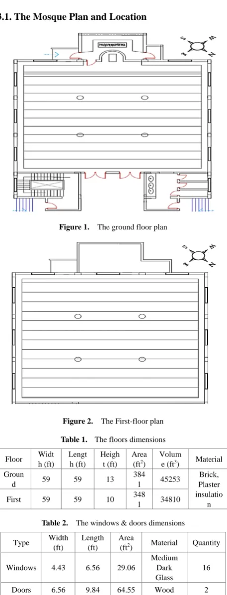
Figure 1. The ground floor plan
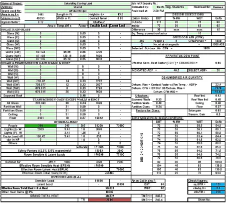
Figure 2. The First-floor plan
Table 1. The floors dimensions
Floor Widt h (ft) Lengt h (ft) Heigh t (ft) Area (ft2)
Volum
e (ft3) Material
Groun
d 59 59 13 384
1 45253
Brick, Plaster insulatio n First 59 59 10 348
1 34810
Table 2. The windows & doors dimensions
Type Width (ft)
Length (ft)
Area
(ft2) Material Quantity
Windows 4.43 6.56 29.06
Medium Dark Glass
16
[image:4.595.307.536.159.758.2]Table 3. Thermal Conditions Condition Dry Bulb Temperature (oF) Wet Bulb Temperature (oF) Relative Humidity (%) Humidity Ratio (g/Ib)
Outside 111 20 76 80
Inside 75 50 63 65
Difference 36 --- --- 15
AlFahad Mosque is placed in Unaizah at latitude = 36.191 oN, and longitude = 44 oE. There is no existing building in front or behind of the building which means that the sides of the building are directly open to the atmosphere shown in figure 3.1 and 3.2
3.1.1. Location
Building Location: Unaizah Qassim Region K.S.A Latitude: 36.191°N
Longitude: 440E
Google map location GPRS
AlWafaa, Unayzah56468
https://goo.gl/maps/EkaiphkgCYS2
3.2. Load Calculations
Cooling load calculations for air conditioning system design are mainly used to determine the volume flow rate of the air system, and tonnes of refrigeration required for the system. It provides the inputs to the system in order to select optimal design alternatives. Cooling load usually can be classified into two categories:
a) External cooling loads: these loads are formed
because of heat gains in the conditioned space from external sources through the building wall and the partition walls. Sources of external loads include the following cooling loads:
Heat gain entering from the exterior walls and roofs.
Solar heat gain transmitted through the windows.
Conductive heat gain coming through the windows.
Heat gain entering from the partition walls and interior doors.
Infiltration of outdoor air into the conditioned space.
b) Internal cooling loads: these loads are formed by
the release of sensible and latent heat from the heat sources inside the conditioned space. These sources contribute internal cooling loads:
People.
Electric lights.
Equipment and appliances.
Heat loads should be calculated based on the procedures outlined in the American Society of Heating, Refrigerating, and Air Conditioning Engineers (ASHRAE) Handbook of Fundamentals. Design heat transmission
coefficients used for cooling loads should be obtained from the Plant Structures Branch and should reflect the actual materials to be specified.
The calculation of space heat load using the transfer function method (TFM) consists of two steps. First, heat loss from exterior walls, roofs, and floors is calculated using conduction transfer function coefficients; and the solar and internal heat gains are calculated directly for the scheduled hour. Second, room transfer function coefficients are used to convert the heat gains to cooling loads, or the heat losses to heating loads. Most of the widely adopted computer software programs for space load calculations, HAP software in our case, are based on the TFM.
The cooling load temperature difference (CLTD) method first calculates the sensible cooling load based on the TFM. The result is divided by the sensible heat gain to generate the CLTD. Cooling load calculation using the CLTD method can be either computer aided or performed manually for a check or rough estimate. The CLTD method is one of the members of the TFM family. In the CLTD method, the CLTD is used to calculate the sensible cooling load for the exterior wall and roofs. Recently, a solar cooling load (SCL) factor has been added which represents the product of the solar heat gain at that hour and the fraction of heat storage effect due to various types of room construction and floor coverings. Cooling load factor (CLF) is used to calculate internal sensible cooling loads. The following are the detailed calculation procedures for CLTD method. [2]
The following equations (3.1-3.7) obtained from [2] are used for calculating the space cooling load due to the heat gained.
Space cooling load due to heat gain through exterior walls, roofs, and conductive gain through glass can be calculated in equation (1) as:
Qrs,w = U×A×(CLTD) (1)
Space cooling load due to solar heat gain through windows can be calculated in equation (2) as:
Qrs,w = As×SCLs×SC (2)
Space cooling load due to heat gain through wall exposed to unconditioned space can be calculated in equation (3) as:
qrs= A×U×(Tun - Tr) (3)
Space cooling load due to heat gain from infiltration can be calculated in equation (4) as:
qs,inf= 60×Vinf×ρo×cpa× (To – Tr) (4)
Space cooling load due to heat gain from people can be calculated in equation (5) as:
qp,t = Np,t×(SHGp) + Np,t×(LHGp) (5)
Space cooling load due to heat gain from electric lights can be calculated in equation (6) as:
Space cooling load due to heat gain from equipment and appliances can be calculated in equation (7) as:
qs,e = 2546×Php×Fload×Fuse (7) 3.2.1. HAP Software
Hourly Analysis Program (HAP) is a computer tool produced by Carrier, a company providing solutions for air conditioning, heating, and refrigeration. The aim of this program is to assist engineers in designing HVAC systems for commercial buildings. It presents two tools in one: estimation of the loads and designing system, and simulation of the energy use and calculation of energy costs. The program is thus split into two parts: HAP system design features and HAP Energy Analysis Features (HAP Carrier 2005).
In the first part, HAP can perform the following tasks:
To calculate design cooling and heating loads for spaces, zones, and coils.
To determine the required airflow rates for spaces, zones, and system.
To size cooling and heating coils.
To size air circulation fans.
To size chillers and boilers.
During the energy analysis, HAP executes the following tasks:
To simulate an hour-by-hour operation of all heating and air conditioning systems.
To simulate an hour-by-hour operation of all plant equipment.
To simulate an hour-by-hour operation of non-HVAC systems.
To calculate the total energy use and energy costs based on the previous simulations.
To generate tabular and graphical reports of hourly, daily, monthly and annual data.
3.2.2. Cooling Load Calculation by Manual Method E20 manual method calculation was done using all equations mentioned in Methodology.
Sample calculation for the ground floor is given below. Note that the overall heat transfer coefficient is taken from the ASHRAE Handbook of Fundamentals based on each material and at 3:00 PM time period.
Space cooling load due to heat gain through walls using Equation 1 is shown in Table 2.
Table 4. Space cooling load due to heat gain through walls
Wall Side Overall Heat Transfer Coefficient (BTU/h.ft2.°F)
Area (ft2)
Temperature Difference (oF)
Sensible Load (BTU/h) Southern
West 0.33 708.88 12 2807
Northern
West 0.33 679.82 8 1795
Southern East 0.33 679.82 25 5608
Northern East 0.33 710.42 14 3282
Space cooling load due to conductive heat gain through glasses using Equation 1 is shown in Table 4.
Table 5. Space cooling load due to solar heat gain through glasses
Glass Side Overall Heat Transfer Coefficient (BTU/h.ft2.°F) Area (ft2) Temperature Difference (oF) Sensible Load (BTU/h)
All Glasses 0.54 232.49 36 4520
Space cooling load due to solar heat gain through glasses using Equation 2 is shown in Table 5.
Table 6. Space cooling load due to solar heat gain through glasses
Glass Side Overall Heat Transfer Coefficient (BTU/h.ft2.°F)
Area (ft2)
Temperature Difference (oF)
Sensible Load (BTU/h) Southern
West 0.65 58.12 85.66 3236
Northern
West 0.65 87.19 138.16 7830
Southern East 0.65 87.19 85.29 4833
Space cooling load due to heat gain through floor using Equation 3 is shown in Table 6.
Table 7. Space cooling load due to heat gain through a floor
Floor Overall Heat Transfer Coefficient (BTU/h.ft2.°F) Area (ft2) Temperature Difference (oF) Sensible Load (BTU/h)
Ground 0.57 3481 10 19842
Table 8. Space cooling load due to heat gain from people
Heat Type Number of People Heat Gain (BTU/h) Load (BTU/h)
Sensible
360 245 88200
Latent 205 73800
Space cooling load due to heat gain from electric lights using Equation 6 is shown in Table 8.
Table 9. Space cooling load due to heat gain from electric lights
Heat Source Conversion Factor
Rated Input of Electric Lights (W)
A ratio of Wattage in Use to Installation Wattage
Allowance Factor for Light Fixtures
Sensible Load (BTU/h)
Electric Lights 3.413 2603 1 1 8876
Space cooling load due to heat gain from equipment using Equation 7 is shown in Table 9.
Table 10. Space cooling load due to heat gain from equipment Heat
Source
Conversion Factor
Rated Horsepower of Machine (hp)
A ratio of Actual Power Required to Rated Power
The ratio of Actually Used Equipment to Total Installed
Sensible Load (BTU/h)
Equipment 2564 0.25 1 1 641
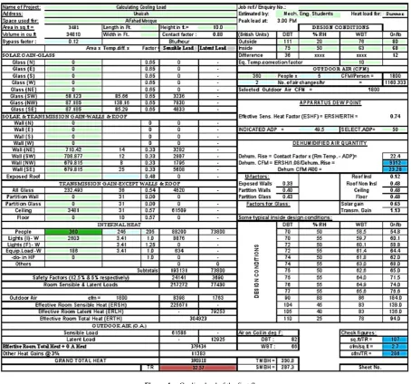
The complete manual cooling load calculation using the same manner above is done for the whole mosque. The ground floor required 28.86 TR as shown in Figure 2. The first floor required 32.57 TR as shown in Figure 3. Therefore, the mosque required 61.43 TR.
E20 SHEET
[image:7.595.71.527.336.746.2]Figure 4. Cooling load of the first floor
3.2.3. Cooling Load Calculation by HAP Software
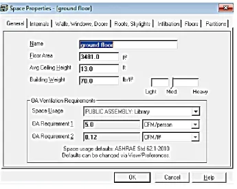
Figure 5. Input weather data for the location of the building.
The program can indicate specific space conditions such as roof, door, lights, windows, people, and equipment, internal and external walls as shown in Figure 6.
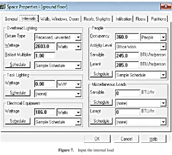
[image:9.595.127.473.418.694.2]Inserting the input load parameters of overhead lighting, task lighting, equipment, people, miscellaneous, and schedule for each one is shown in Figure 7.
Figure 7. Input the internal load
Inserting the external walls area, the number of windows, doors on walls, and their components is shown in Figure 8.
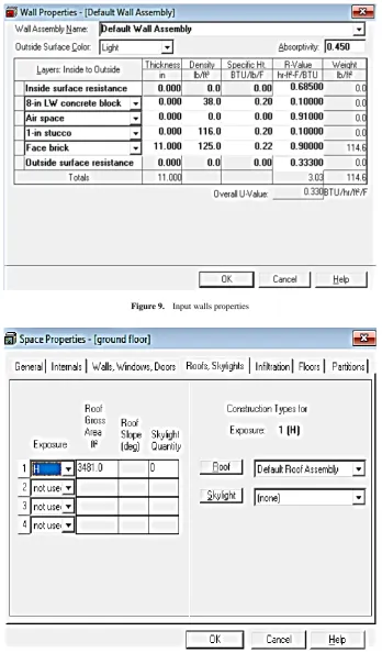
[image:10.595.128.469.443.708.2]Inserting the walls properties is shown in Figure 9. The roof component design and calculation are shown in Figure 10
[image:11.595.124.473.115.710.2]Figure 9. Input walls properties
[image:11.595.127.468.119.390.2]One air change per hour was selected for infiltration and the internal wall in the building was considered as a partition. The calculation of cooling load using HAP is shown in Figure 11. Based on HAP calculation the mosque required 56 TR.
Figure 11. Cooling load by HAP
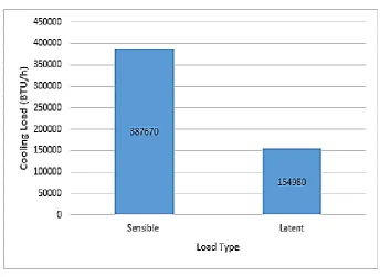
The Bar Graph of cooling load due to sensible and latent heat is shown in Figure 12.
Figure 12. Cooling load results from sensible and latent heat
[image:12.595.125.470.441.692.2]Figure 13. Distribution of heat gain
Figure 14. Comparison between cooling load calculation methods
The comparison between the cooling load calculation using E20 and HAP, and using the market's method is Bar Graph shown in Figure 14
The cooling load using E20 manual method was 61.43 TR. It was 56 TR using HAP software. It was 47 TR using the markets methods. The difference between E20 and HAP results was 8.8 %. The difference between E20 and markets method was 23.5 %.
4. Conclusions
The mosque required 61.43 TR based on E20 manual method calculation, while required 56 TR based on HAP
[image:13.595.154.441.327.560.2]advantage of efficient cooling, noiseless, and comfort for the prayers.
5. Nomenclature
Qrs,w = space sensible cooling load (BTU/h).
U = overall heat transfer coefficient of exterior wall or roof (BTU/h.ft2.°F).
A = area of an exterior wall, roof (ft2).
CLTD = cooling load temperature difference (°F). Qrs,w = space sensible cooling load from solar heat gain transmitted through the window facing a specific direction (BTU/h).
As, = sunlit area (ft2).
SCLs = solar cooling load for sunlit glass facing specific direction (BTU/h.ft2).
SC = shading coefficient.
qrs = sensible heat gain transferred through the partitioned walls, interior windows, and doors (BTU/h).
U = overall heat transfer coefficient of a partitioned wall, interior glass, or roof (BTU/h.ft2.°F).
A = area of a partitioned wall, interior glass, or roof (ft2). Tun = daily mean air temperature of adjacent area that is unconditioned (°F).
Tr = space temperature (°F).
qp,t = heat gain for occupants staying in a conditioned space at time t (BTU/h).
Np,t = number of occupants in conditioned space at time t.
SHGp = sensible heat gain of each person (BTU/h). LHGp = latent heat gain of each person (BTU/h). qs.l = sensible heat gain released from the electric lights (BTU/h).
Wlamp = rated input of electric lights (W).
Fusl = ratio of wattage in use to installation wattage. Fal = allowance factor for light fixtures.
,qs,e = sensible heat gain due to the machine load when a motor is located inside the conditioned space (BTU/h). .
Php = rated horsepower of machine (hp).
Fload = load factor indicating the ratio of actual power required to rated power.
Fuse = use factor indicating the ratio of actually used equipment and appliance to total installed.
Acknowledgement
s
The Qassim University allotted SDP (senior design project) for the fulfillment to the Award the engineering Degree. The students of Mechanical Engineering Department from Unaizah College of Engineering Selected the senior design project (SDP) [1] on “Comparison of Cooling Load Calculation by E20 and HAP software” for the Mosque at Unaizah Qassim Region Saudi Arabia. In SDP, group of students as team under the supervision of one or more faculty members. During
senior project design Students are gaining the knowledge on Design, Estimation and Simulation of the project to expose after graduation.
REFERENCES
AlAttyih, W., Abdel-samie, M., Emad, A., ElKholy, S., and [1]
Esmaeil, K. “Senior Design Project Courses Control and Evaluation”, Qassim University Report, 2017.
Shan K. Wang, "Handbook of Air Conditioning and [2]
Refrigeration", second edition.
Bagheri, F., "Development of Efficient Air Conditioning and [3]
Refrigeration System for Service Vehicles", Simon Fraser University, 2016.
kosar K., national center for Energy Management and [4]
Building Technologies, 2002.
Douglas, K., "Dehumidification Issues of Standard 62-1989", [5]
ASHRAE Journal, 1998.
Richard Taft, "Rx for Health-Care HVAC", ASHRAE [6]
Journal, 2006.
Sogut M. Ziya, "Exergetic and Environmental Assessment [7]
of Room Air Conditioners in Turkish Market", 2012. Bajwa, M., Aksugur, E., and Al-Otaibi, G., "The Potential of [8]
the Evaporative Cooling Techniques in the Gulf Region of the Kingdom of Saudi Arabia", 1993.
Bajwa, M., "Effectiveness of Nocturnal Ventilative Passive [9]
Cooling Strategy in the Maritime Desert Climate of the Arabian Gulf Region", 1992.
AlHemiddi, N. A., and AlSaud, K. A. M., "The Effect of a [10]
Ventilated Interior Courtyard on the Thermal Performance of a House in a Hot Arid Region", 2001.
AlAidroos, A., and Krarti, M., "Evaluation of Passive [11]
Cooling Systems for Residential Buildings in the Kingdom of Saudi Arabia", Journal of Solar Energy Engineering, 2016.
Mohsen, M., Olwi, I., and Ghazi, M., "Aerodynamics and [12]
Ventilation in Buildings: Experimental Investigation", 1987.
Al-Sulaiman, F., and Zubair, S., "A Survey of Energy [13]
Consumption and Failure Patterns of Residential Air-Conditioning Units in Eastern Saudi Arabia", 1996. Carrier. (n.d.) Retrieved from https://www.carrier.com/com [14]