http://dx.doi.org/10.4236/jemaa.2014.66012
Modeling of OFDM Based Transceiver for
Broadband Powerline Communication
Syed Samser Ali
1, Amitabha Bhattacharya
2, Dipak Ranjan Poddar
31Department of Electronics and Communication Engineering, Durgapur Institute of Advanced Technology &
Management, Durgapur, India
2Department of Electronics & Electrical Communication Engineering, Indian Institute of Technology, Kharagpur,
India
3Department of Electronics and Telecommunication Engineering, Jadavpur University, Kolkata, India
Email: [email protected]
Received 24 March 2014; revised 22 April 2014; accepted 18 May 2014
Copyright © 2014 by authors and Scientific Research Publishing Inc.
This work is licensed under the Creative Commons Attribution International License (CC BY). http://creativecommons.org/licenses/by/4.0/
Abstract
In the recent past power line communication has emerged as an attractive choice for high speed data transfer and is looked upon as inexpensive and reliable media suitable for broadband inter-net access, home and office automation, in-vehicle data communication etc. In this paper we pre-sent an architecture for the physical layer of a PLC transceiver based on Orthogonal Frequency Di-vision Multiplexing (OFDM) and the impact on multipath distortion for PLC transmission in terms of bit error rate. Since there is no standard PLC channel model available, a widely accepted multi-path channel model is used for simulation purpose. Simulation results as well as FPGA synthesis verify the effectiveness of the proposed architecture for PLC modem design at 110 Mbps data rate.
Keywords
OFDM, Power Line Communication (PLC), Multipath Channel, FPGA
1. Introduction
multipath stemming from impedance mismatches are the other factors which have to be dealt with in order to establish a reliable high-speed PLC system. Considering power line noise and attenuation, the frequency zone between 1 - 30 MHz is believed to be ideal for the operation of PLC systems [3] [4]. This frequency range is also used by Amateur radio operators, international short wave broadcasters and a variety of communication systems, thus a potential for harmful interference with other user exists [5]. Orthogonal Frequency Division Multiplexing (OFDM) is considered as the most favourable modulation scheme for a severe communication en-vironment such as the PLC channel [6]. Comparing to single carrier modulation scheme OFDM segments the available bandwidth into a large number of closely-spaced orthogonal subcarriers, each occupying a much nar-rower bandwidth. In this way, OFDM can combat frequency selective attenuation and multipath propagation ef-fect. This paper presents the design of the physical layer of a PLC transceiver based on the OFDM modulation scheme and the impact of multipath distortion on PLC transmission in terms of bit error rate (BER). For the completeness of the study, Zimmermann and Dostert’s well-known PLC channel model is taken into considera-tion [7]. The designed system is fully described using VHDL and synthesized on a Xilinx Spartan 6 FPGA de-vice [8]. Every OFDM system consists of a pair of a transmitter and a receiver circuit, which are implemented digitally on two different FPGA chips. The tested OFDM systems differ on the adopted modulation technique and the number of subcarriers used. The choice to develop the communication systems on FPGA chips provides a low-cost, easy to implement, digital solution, and the fact that FPGAs are reprogrammable devices makes possible the reuse of the same FPGA chips for the different OFDM systems. All OFDM systems occupy the frequency zone 1 - 30 MHz.
2. System Design
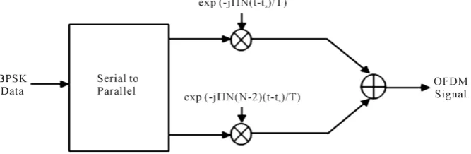
In OFDM, the parallel data streams are first mapped into BPSK data which then modulate a number of subcar-riers using discrete Fourier transform (DFT) producing an OFDM signal. An OFDM symbol starting at t = ts, carrying a sequence diof BPSK symbols in N subcarriers can be expressed by the following complex baseband representation [9]:
( )
(
)
( )
1 22
exp 2π ,
2
0, N
i s s s
N i
s s
N i
s t S j t t t t t T
T
s t t t t t T
−
=−
= + − ≤ ≤ +
= < ∧ > +
∑
(1)
where T is the symbol duration. Figure 1 shows the basic operation of OFDM.
[image:2.595.148.482.595.704.2]An important task in the design of OFDM systems is the choice of the different parameters and the tradeoffs between them. Three requirements are of major importance: bandwidth, bit rate and delay spread [9]. According to Nee et al. [9], a good length of the CP should be around two to four times the root-mean-squared delay spread. The longer the symbol duration relative to the CP length, lesser is the loss in SNR, due to the CP. At the same time, this means a bigger number of subcarriers with less spacing given a specific bandwidth, adding extra im-plementation complexity and leading to problems related to frequency and phase offset. OFDM offers a great spectral efficiency which is necessary for broadband communications through a channel with very limited spec-tral resources like the power line channel. The long symbol period in OFDM gives the technique extra strength
against multipath propagation and ISI. Although the insertion of a cyclic prefix reduces the useful data rate of the system, it gets rid of any ISI or ICI that can result from multipath when designed to have a longer duration than the delay spread of the PLC channel. The core element of OFDM is the IDFT/DFT process. This can be implemented in practice using the FFT algorithm in a very efficient and cost-effective way. The power line net-work is a hostile channel when considering broadband high-speed communications. One of the most crucial properties of this channel affecting high-speed communications is the presence of random time-varying impul-sive noise. OFDM performs better than single-carrier modulation techniques in the presence of impulimpul-sive noise [10] [11]. In the receiver part of OFDM, the received signal including impulsive noise is divided by the number of subcarriers through the DFT operation, which results in a significant reduction of the effect of impulsive noise.
A general block diagram of the proposed PLC transceiver is shown in Figure 2. At the transmitter side, the information bits first undergo channel coding and interleaving before mapping into BPSK symbols. Pilots are inserted in the data to detect the channel transfer characteristics. Then the data stream is then converted to a pa-rallel stream that is modulated by means of a 4096-point IFFT block. Each OFDM symbol generated by this block is composed of 1974 data subcarriers and 74 guard subcarriers. The modulated data is converted back to a serial stream and a cyclic prefix (CP) of 1252 samples is inserted at the beginning of the symbol, in order to avoid inter symbol interference (ISI) in the case of any delay at the receiver. At the receiver side, more or less the opposite happens in addition to the required synchronization and channel equalization using the information delivered by the pilot symbols.
For the PLC channel model a widely accepted multipath channel model introduced by Zimmermann and Dostert [7] is used for simulation purpose.The model is based on practical measurements of actual power line networks and is given by the channel transfer function:
( )
(
0 1)
2π( )1 attenuation portion delay portion
e e
k P
i i p
N
a a f d j f d v
i i
H f g − + −
=
=
∑
⋅ ⋅ (2) [image:3.595.91.537.411.704.2]where Npis the number of multipaths, giand diare the weighting factor and length of the i th path respectively.
Frequency-dependant attenuation is modeled by the parameters a0, a1 and k. In the model, the first exponential presents attenuation in the PLC channel, whereas the second exponential, with the propagation speed vp, de-scribes the echo scenario. The attenuation parameters for a 4-path model and a 15-path model were obtained us-ing physical measurements in [2] and are summarized in Table 1 and Table 2 respectively.
During simulation the periodic synchronous Impulsive noise and AWGN are employed simultaneously on the power line channel and they have different impacts upon the communication performance.
3. Synthesis and Simulation Results
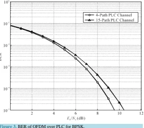
In order to evaluate the bit error rate (BER) performance of the designed transceiver over power line noise, the receiver response is simulated using MATLAB R2013a and the resulting BER plot is shown in Figure 3. On the basis of Eb No it is clear that 15 path BPSK requires more energy per bit than 4 path BPSK model. But it re-sults into the higher data for a system. The total designed system was described using hardware descriptive lan-guage and synthesized on the Xilinx Spartan 6 FPGA device using the Xilinx ISE 14.4 software.
4. Conclusion
We have presented an architecture for the physical layer of a PLC transceiver based on OFDM and the system synthesized on a Xilinx Spartan 6 FPGA device, supports data rate up to 110 Mbps. The modulation scheme and
Table 1.Parameters of the 4-path PLC channel model.
Attenuation parameters
κ = 1 ao = 0 a1 = 7.8 × 10⁻¹⁰ m/sec
Path parameters
i gi di/m i gi di/m
1 0.64 200 3 −0.15 411
[image:4.595.155.442.338.719.2]2 0.38 222.4 4 0.05 490
Table 2. Parameters of the 15-path PLC channel model.
Attenuation parameters
κ = 1 ao = 0 a1 = 7.8 × 10⁻¹⁰ m/sec
Path parameters
i gi di/m i gi di/m
1 0.029 90 9 0.071 411
2 0.043 102 10 −0.035 490
3 0.103 113 11 0.065 567
4 −0.058 143 12 −0.055 740
5 −0.045 148 13 0.042 960
6 −0.040 200 14 −0.059 1130
7 0.038 260 15 0.049 1250
Figure 3. BER of OFDM over PLC for BPSK.
hardware architecture are designed to combat the impairments of the hostile power line channel and provide high quality communication. The simulation results verified the correct operation and performance of the tran-sceiver.
References
[1] Ferreira, H.C., Lampe, L., Newbury, J. and Swart, T.G. (2010) Power Line Communications: Theory and Applica tions for Narrowband and Broadband Communications over Power Lines. Wiley.
[2] Zimmermann, M. and Dostert, K. (2002) Analysis and Modeling of Impulsive Noise in Broad-Band Powerline Com-munications. Electromagnetic Compatibility, IEEE Transactions on Electromagnetic Compatibility, 44, 249-258. http://dx.doi.org/10.1109/15.990732
[3] Gotz, M., Rapp, M. and Dostert, K. (2004) Power Line Channel Characteristics and Their Effect on Communication System Design. IEEE Communications Magazine, 42, 78-86. http://dx.doi.org/10.1109/MCOM.2004.1284933 [4] Home Plug Powerline Alliance: HomePlug AV White Paper.
www.homeplug.org/products/whitepapers/HPAV-White-paper_050818.pdf.
[5] Zhang, M. and Lauber, W. (2008) Evaluation of the Interference Potential of In-Home Power Line Communication Systems. IEEE, International Symposium on Power Line Communications and Its Applications, Jeju Island, 263-268. [6] Pavlidou, N., Han Vinck, A., Yazdani, J. and Honary, B. (2003) Power Line Communications: State of the Art and
Fu-ture Trends. IEEE Communications Magazine, 41, 34-40. http://dx.doi.org/10.1109/MCOM.2003.1193972
[7] Zimmermann M. and Dostert, K. (2002) A Multipath Model for the Power-Line Channel. IEEE Transactions on Communications, 50, 553-559. http://dx.doi.org/10.1109/26.996069
[8] Xilinx (2011) Xilinx DS160 Spartan-6 FPGA Family Data Sheet. Xilinx Corporation.
[9] Nee, R.V. and Prasad, R. (2000) OFDM for Wireless Multimedia Communications. Artech House.
[10] Ma, Y.H., So, P.L. and Gunawan, E (2005) Performance Analysis of OFDM Systems for Broadband Power Line Communications under Impulsive Noise and Multipath. IEEE Transactions on Power Delivery, 20, 674-681.
http://dx.doi.org/10.1109/TPWRD.2005.844320