PLC based Implementation of Fuzzy Controller for Boost
Converter
Ahmed Sadeq Hunaish,
Department of Electrical Engineering, College of Engineering, University of Basra
Basra, Iraq
Jawad Radhi,
Department of Electrical Engineering, College of Engineering, University of Basra
Basra, Iraq
ABSTRACT
In this paper, the two-input fuzzy logic controller (FLC) and proportional –integral–derivative (PID) controller for boost converter output-voltage regulation are proposed by using Siemens Programmable Logic Controller (PLC). Here the output voltage has been used as a closed loop feedback to determine the output voltage error (e) and the change in error (∆e) as two inputs to the controller. The elements of the boost converter as inductance and capacitor have been selected to insure continues operating mode (CCM) and low output voltage ripple. The proposal is implemented by using Programmable Logic Controller (PLC) on 150 watts prototype and compare (FLC) with (PID) results. The experimental results show that the FLC has a good output voltage response compare with PID controller response.
General Terms
Fuzzy logic controller (FLC), Programmable Logic Controller (PLC), continues operating mode (CCM)
Keywords
Fuzzy logic controller (FLC); proportional –integral– derivative (PID) controller; Programmable Logic Controller (PLC),
1.
INTRODUCTION
Dc-dc power converters are widely used in industrial and domestic applications. From control point of view, operation of these converters can be considered as a tracking issue, where the output voltage (Vo) is required to follow a reference command with low transient and low steady state error. The dc–dc converters provide a dc output voltage controlled with pulse width-modulation (PWM) switching technique. The two general methods to control switching operation are: 1) current-mode control and 2) voltage-mode control. The first method uses outer output voltage loop that senses the output voltage and inner current loop that senses the inductor current for feedback purposes. The second method uses a closed loop that senses the output voltage for feedback [1], [2]. In this paper, the close loop voltage feedback control method has been used due to its simplification. In the first step of the experimental procedure, the output voltage is measured and reduced to calculate the error and the change in error.
Recently, the fuzzy logic controller (FLC) as nonlinear controller to control power electronic converters design and implementation sides receiving increasing attention [3]-[9].Also, there are several researches study using of conventional proportional –integral–derivative (PID) controller [10] – [16]. The idea to have a fuzzy logic controller system in dc-dc converter is to ensure desired
voltage output can be produced efficiently as compared to proportional –integral –derivative (PID) system. To improve the converter’s performance like providing less overshoot and a faster settling time fuzzy logic based controller is designed [17]. As a result, the linear controller could not perform adequately when subjected to large load variation. In addition, the linear controller may sustain difficulty in handling momentary input voltage reference change [16]. Therefore, the fuzzy logic controller (FLC) is used to overcome these constraints as non-linearity. The performance of closed loop circuit (with FLC) is better than the open loop circuit, where there are no overshoot and better settling time compared to open loop [18].
The aim of this paper is to design a fuzzy logic controller based on Programmable Logic Controller (PLC) and show the effect of the load variation on the system behavior and compare the results with PID controller results.
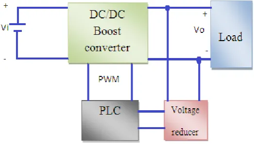
[image:1.595.317.579.574.725.2]“Fig. 1,” represents the block diagram of the system. In this system, the output voltage (Vo) has been scaled down to fit the analog input of the PLC (0-10V), this analog input has been used to calculate the error and the change in error then feed them to the control program (PID or FLC) that is written by using Structured Control Language (SCL) at the SIMATIC S7 CPUs . (SCL) is a high-level, PASCAL - based programming language. The FLC program determines the change in the duty cycle (∆D) then duty ratio (D) of the MOSFET switching device. The change in the duty cycle (∆D) is added to the previous duty ratio (D). The desired duty ratio (D) is applied to Pulse Width Modulation (PWM) generator, the generator output is applied to photo coupler driving the switching MOSFET transistor.
= (1) Where, is the minimum value of the inductor, fs is the
switching frequency “Hz” and R is the output resistance (Ω).
(2)
Using switching frequency fs 10 kHz, the maximum expected
duty ratio 0.6 and maximum R value 15Ω, from equation 1:
=0.072 mH.
L = 0.8 mH to insure continuous current mode operation.
2.2
Capacitor
While, capacitor value affects the ripple of the output voltage (Vo), to maintain an acceptable ripple value (∆V), approximate expression for the required capacitance can be driven as [19]:
= (3)
Where, Cmin is the minimum value of the capacitor.
Using switching frequency 10 kHz, the maximum expected duty ratio 0.6, minimum R value 7.5Ω and ∆V value is 0.2V, from equation 3:
= 1200 µF
C = 3300 µF to insure low output voltage ripple.
3.
FUZZY LOGIC CONTROLLER
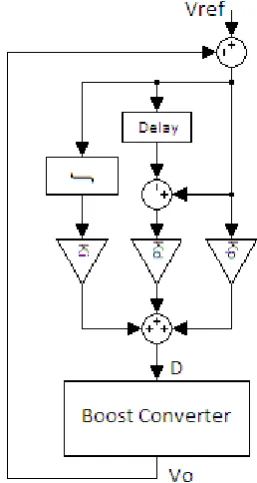
[image:2.595.324.549.83.192.2]Here, two inputs and one output Fuzzy Logic Controller has been used. The first input is the voltage error, the second is the change in error and change in duty cycle (∆D) is the output. The FLC is represented in Fig.3. The adapted membership functions of the inputs and output are shown in Fig.4 and Fig.5, rules as in Table. 1.
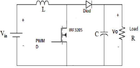
[image:2.595.358.496.230.483.2]Fig 2: Power circuit of the boost converter.
Fig 3: Fuzzy Logic Controller Structure
[image:2.595.342.554.527.718.2]Fig 5: The membership functions set of the output.
Table 1. Rules of duty change ∆D
∆e
e N Z B
N N N N
Z N Z P
P Z P P
Where, N is Negative, Z is Zero and P is Positive.
As example of the utilization of the table above the rule: IF (e is P) AND (∆e is Z) THEN(∆D is P). This rule states that when the error is (P) and the change in error is zero ,that’s mean the output voltag is less than the designed voltage (Vref), but there is no change in the value of the output voltage, that’s mean the duty cycle must be increased, therfore the new duty (D) must increase by positive (P) ∆D to increase output voltage. The defuzzification method that is used is weighted average method. This method is valid for symmetrical output membership functions as singleton [20]. Each membership function is weighted by its maximum membership value. The output is defined by
(4) [image:3.595.77.286.76.230.2]
where µ(xᵢ) is the maximum of the ith membership function, xᵢ is the ith input value and y is the output function value.
Fig 6: PID Controller Structure
4.
PID CONTROLLER
The PID controller is demonstreted in Fig. 6, the PID controller parameter are tuned to give the optimal performance; . = 0.0001, = 10.0 and = 0.00021. The PID equation is:
∆D = .e + + . (5)
5.
EXPEREMENTAL RESULTS
The proposed control systems are implemented in Programmable Logic Controller (PLC) and tested on the system as in Fig.7. The PLC program flow chart for (FLC) is as in Fig.8, when the system start-up, the duty ratio (D) is set to intial value and applied to MOSFET gate .The converter output voltage (Vo) is measured with sample time (1 msec and resolution of 12bit). Error (e), is the difference between the reference voltage (Vref) and output voltage (Vo), is calculated, also change in error (∆e) is the difference of the current error and previous error, then e and ∆e are applied to FLC program to find the new ∆D that’s added to the previous duty ratio (D) to compensate the voltege error.
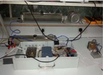
[image:3.595.49.291.265.357.2]Fig 7: The proposed control system implementation.
Fig 8: Flow chart of the PLC program. Start
Set initial value for Duty ratio (D)
Sample and measure
Calculate error and change in error
Fuzzy Logic Controller Program to Calculate the new Duty
[image:4.595.214.383.418.680.2]a. R=7.5Ω,Vin=12V&Vref=24V(5V/div&0.1s/div)
c: R=7.5Ω,Vin=12V&Vref=30V(10V/div&0.05s/div)
e: R=7.5Ω,Vin=24V&Vref=30V(10V/div&0.1s/div)
b. R=15Ω,Vin=12V&Vref=24V (5V/div&0.1s/div)
d: R=15Ω,Vin=12V&Vref=30V(10V/div&0.1s/div)
[image:5.595.58.561.70.227.2]f: R=15Ω,Vin=24V&Vref=30V(10V/div&0.1s/div)
Fig 9: Startup phase for different loads and different output and input voltages under Fuzzy Logic Controller technique
Fig.9.(a, b, c, d, e and f) represent the system start-up phases response under fuzzy logic controller technique for different loads with input voltages and output reference voltages as shown above. Fig.9.(a, b, c, d, e and f) which take approximately rise time 18 msec, 25 msec, 16 msec, 20 msec, 10 msec and 5 msec respectively and the settling times (with 5% error) are 136msec, 120msec, 26msec, 104msec, 160msec and 172msec respectively
[image:5.595.63.559.276.432.2]a: R=7.5Ω, Vin=12V&Vref=24V(5V/div&0.1s/div)
c: R=7.5Ω,Vin=12V&Vref=30V(5V/div&0.1s/div)
e: R=7.5Ω,Vin=24V&Vref=30V(10V/div&0.1s/div)
b: R=15Ω,Vin=12V&Vref=24V(5V/div&0.1s/div)
d: R=15Ω,Vin=12V&Vref=30V(5V/div&0.1s/div)
[image:6.595.55.558.70.229.2]f: R=15Ω,Vin=24V&Vref=30V(10V/div&0.1s/div)
Fig 10: Startup phase for different loads and different output and input voltages under PID controller technique.
Fig.10.(a, b, c, d, e and f) represent the system start-up phases response under fuzzy logic controller technique for different loads with input voltages and output reference voltages (Vref) as shown above. Fig.10.(a, b, c, d, e and f) which take approximately rise time 53msec, 76msec, 10msec, 82msec, 15msec and 10msec respectively and the settling time (with 5% error) are 96msec, 92msec, 126msec, 172msec, 128msec and
[image:6.595.58.559.480.645.2]a: R=7.5-15Ω,Vin=12V&Vref=24V(5V/div&0.1s/div)
c: R=7.5-15Ω,Vin=12V&Vref=30V(10V/div&0.1s/div)
e: R=7.5-15Ω,Vin=24V&Vref=30V(5V/div&0.1s/div)
b: R=15-7.5Ω,Vin=12V&Vref=24V(5V/div&0.1s/div)
d: R=15-7.5Ω,Vin=12V&Vref=30V(10V/div&0.1s/div)
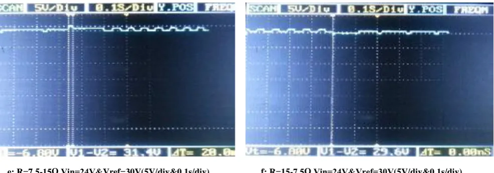
[image:7.595.59.555.70.228.2]f: R=15-7.5Ω,Vin=24V&Vref=30V(5V/div&0.1s/div)
Fig 11: Load step change for different output and input voltages under Fuzzy Logic Controller technique.
[image:7.595.63.556.479.652.2]a: R=7.5-15Ω,Vin=12V&Vref=24V(5V/div&0.1s/div)
c: R=7.5-15Ω,Vin=12V&Vref=30V(10V/div&0.1s/div)
e: R=7.5-15Ω,Vin=24V&Vref=30V(5V/div&0.1s/div)
b: R=15-7.5Ω,Vin=12V&Vref=24V(5V/div&0.1s/div)
d: R=15-7.5Ω,Vin=12V&Vref=30V(10V/div&0.1s/div)
[image:8.595.54.559.71.228.2]f: R=15-7.5Ω,Vin=24V&Vref=30V(5V/div&0.1s/div)
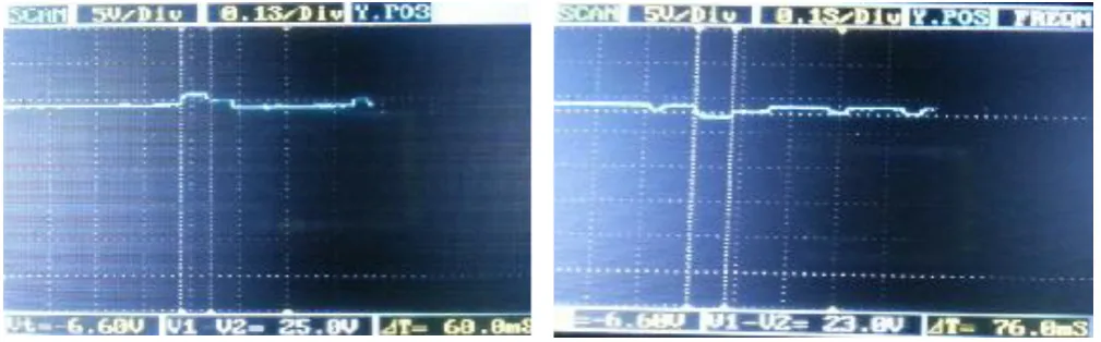
Fig 12: Load step change for different output and input voltages under PID Controller technique
Fig.12 (a, b, c, d, e and f) show the load step change respons for different output and input voltages under PID Controller technique. In Fig.12 (a, b, c, d, e and f) the time required to return the previous output voltages are approximately 60msec, 76msec, 100msec, 100msec, 64msec and 0.0msec respectively.
6.
CONCLUSI0N
[image:8.595.62.558.276.431.2]work adopts the frequently used PID and FLC. As it is clear from Fig.9(a, b, c, d, e and f) and Fig. 10.(a, b, c, d, e and f), the start-up response of boost converter for different loads using FLC with the shown input voltage (Vin) and output reference voltage (Vref), the response curves have rise times and settling times less than that for PID with the same Vin and Vref, but the FLC has an overshoot ratio higher than that for PID response only in Fig.9. (b, d, e and f ) and Fig. 10.(b, d, e and f). Also the response curves of the load step change mode using FLC have settling time less than that for PID response curves.
7.
REFERENCES
[1] B. J. 2004. DC-DC Converters - Dynamic Model Design and Experimental Verification. Doctoral Dissertation, Lund University, Department of Industrial Electrical Engineering and Automation, pp.33-36.
[2] Leyva-Ramos J. and Morales-Saldaña J. A. Sept 1998. A design criteria for the current gain in current-programed regulators. IEEE Trans. Ind. Electron.,vol. 14, pp. 568– 573,.
[3] W. D. , April 2013. Fuzzy PI Controllers Performance on Boost Converter. IJECE.,Vol. 3, No. 2, pp. 215-220. [4] Ul-Alam Md. Sh., M. Q. and Rahman K. M. December
2010. Fuzzy Logic Based Sliding Mode Controlled DCDC Boost Converter. 6th International Conference on Electrical and Computer Engineering( ICECE) 2010, Dhaka, Bangladesh, pp.70-73,18-20.
[5] D. K. , JUNE 2000. An Implementation of Fuzzy Logic Controller on the Reconfigurable FPGA System. IEEE Transactions on Industrial Electronics, vol. 47, no. 3,pp.703-715.
[6] B.-J. C., S. K., and Kim B.K.. APRIL 2000. Design and Stability Analysis of Single-Input Fuzzy Logic Controller. IEEE Transactions on Systems, man, and Cybrnetics—part B, vol. 30, no. 2,pp.303-309.
[7] F. T. , Z. S. and Ayob S. M. 2012.FPGA Implementation of a Single-Input Fuzzy Logic Controller for Boost Converter With the Absence of an External Analog-to-Digital Converter. IEEE Transactions on Industrial Electronics, vol. 59,no. 2,pp.1208-1216. [8] Patella B. J., Al.P., A. Z. and D.M. 2003.
High-Frequency Digital PWM Controller IC for DC–DC Converters. IEEE Transactions on Power Electronics, volL. 18, no. 1, pp.438-446.
[9] F. T., Z. S. and Ayob S.M. 2010. Implementation of Single Input Fuzzy Logic Controller for Boost DC to
DC Power Converter. IEEE International Conference on Power and Drive Energy (PEC on 2010), pp.797 – 802. [10] Arikatla V. P. and Abu Qahouq J. A. 2011. DC-DC
Power Converter with Digital PID Controller. Applied Power Electronics Conference and Exposition (APEC), “Twenty-Sixth Annual IEEE, pp. 327 – 330.
[11] S. A., G. U. and M. Ch., 2004. Design of PID Controller for Boost Converter with RHS Zero. Power Electronics and Motion Control Conference, the 4th International .vol. 2, pp. 532 – 537.
[12] S. Ch., P. A. and I. G. 2011. Auto-tuned, Discrete PID Controller for DC-DC Converter for fast transient response. Power Electronics (IICPE), 2010 India International Conference on, Digital Object Identifier. [13] B. J. and V. A. 2008. FPGA Implementation of QFT
based Controller for a Buck type DC-DC Power Converter and Comparison with Fractional and Integral Order PID Controllers. Control and Modeling for Power Electronics, COMPEL 2008. 11th Workshop on, pp.1 – 6.
[14] L. G. 2007. Implementation of Digital PID Controllers for DC-DC Converters using Digital Signal Processors. Electro/Information Technology, 2007 IEEE International Conference on, pp. 306 – 311.
[15] S. K. and Krein Ph. T. 2010. PID Controller Tuning in a DC-DC Converter: A Geometric Approach for Minimum Transient Recovery Time. Control and Modeling for Power Electronics (COMPEL), 2010 IEEE 12th Workshop on , pp. 1- 6.
[16] J. A., I. C., G. E., P. M., and A. M. 2001. A stable design of PI control for dc–dc converters with an RHS zero. IEEE Trans. Circuits Syst. I, Fundam Theory Appl. vol. 48, no. 1, pp. 103–106.
[17] H. T., Parimi A. M. and Rao U. M. 2013. Modeling of DC---DC Boost Converter using Fuzzy Logic Controller for Solar Energy System Applications. Microelectronics and Electronics (Prime Asia), 2013 IEEE Asia Pacific Conference, pp. 147 – 152, 19-21.
[18] Nik Ismail N.F., I. M., R. B. and D.Johari. 2010. Fuzzy Logic Controller on DC/DC Boost Converter. Power and Energy (PECon), 2010 IEEE International Conference on. pp. 661 – 666.
[19] A. Oi. 2005. Design and Simulation of Photovoltaic Water Pumping System. Ms.C. thesis, California Polytechnic State University. pp.32, 40 – 43.