Design of Vertical Wall-to-Light Solar Photovoltaic
Circuit by Holtek Microprocessor
Kao-Feng Yarn
*Department of Electronic and Optoelectronic Application Engineering, Far East University, Taiwan 744, ROC
**Department of Aircraft Maintenance, Far East University, Taiwan 744, ROC
DOI: 10.29322/IJSRP.9.06.2019.p9084 http://dx.doi.org/10.29322/IJSRP.9.06.2019.p9084
Abstract- In this study, the solar detector is used as a light source sensor by means of a photodetector is proposed. After using the HT66F50 single-chip processing microprocessor, the signal is output to the stepping motor. In this way, the motor can be adjusted in an automatic manner to adjust the solar panel to the characteristics of the required angle. The researched results can be used as a reference for relevant researchers.
Index Terms- photo-voltage modules, stepping motor, shading device, Holtek, HT66F50 microprocessor, application examples
I. INTRODUCTION
I
n the 21st century, human beings are facing climate change, the lack of energy and resources, and the increasingly serious environmental pollution. The research and development and application of green energy, especially solar energy, have become the focus of exhibitions in the global industry and academia. The introduction is widely seen in various flat electronic media and will not be described again. [1-5] In the solar power supply system, the "city parallel type" is used when the sunshine is sufficient, and the solar battery supplies power to the load of the home. If there is excess power, it is stored separately. When the volume is insufficient, the required power is provided by the company. Because the power is not enough, it can be provided by the power company. Unlike the self-sufficient "independent power storage system", it has to increase the cost in order to prepare a large capacity, and it does not consider the distribution problem when the "feedback power system" is to be sold to the company. Compared with the "independent power storage system" and the "feedback power system", the "city parallel type" may be suitable for general use and home use. However, when we consider the use of "electric parallel solar system" in the city, because there is limited space available, it seems that there is no place to install solar panels except for the roof of each building, and the solar panels that are erected are limited; When there are other uses for the roof, there is nowhere to be used.For high-rise buildings in the city, in fact, the wall area of buildings is often larger than that of the roof. Therefore, it is necessary to erect solar panels on the walls of the building's sunny side, which should effectively increase the area of solar panels. However, if the solar panel is directly embedded in the wall, the efficiency of the illumination angle problem can be poor. A solar panel that is tilted vertically on the vertical side may be covered by the upper shadow to cover the lower solar panel. Therefore, we plan to erect a light-directed system that can adjust the solar panel with the sun angle on the wall of the building, that is, a “wall-to-light electric system” because the angle of the solar panel is adjustable to obtain better efficiency.
"Vertical wall type solar photovoltaic system" installs the solar cell on the wall of the building according to the structure of the blinds, uses the photodetector to detect the angle of the sun, and sends the sunshine angle data to the micro control; after the micro control determines the message, it is decided The solar panel angle control motor will be adjusted to the desired angle. The microcontroller used in our system is the Holtek HT66F system microcontroller.
II. WORKING PRINCIPLE
illumination angle problem. If the solar panel is designed to be tilted vertically, it may be covered by the upper layer to cover the lower solar panel. Therefore, it is generally evaluated that the design of the solar photovoltaic module on the vertical façade of the building is considered suitable for high latitudes and not for Taiwan.
However, urban space is limited, and solar panels are placed on the walls of the building's sunny side. In the case of the decline in the cost of solar panels, more and more considerations are being made. Therefore, we design a solar panel that is tilted vertically on the vertical surface and a light-reflecting device, so that the tilt angle of the solar panel can be adjusted with the angle of sunlight, and the solar panel can obtain better efficiency. The time when the lower solar panels are covered by the upper shadows is actually limited to the noon in summer, and the solar panels can be effectively operated in other seasons and during the day.
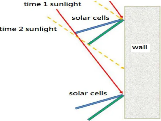
[image:2.612.216.394.208.407.2]This "vertical wall-to-light solar photovoltaic system" installs solar cells on the walls of buildings in a structure similar to blinds, but not as close as blinds, because it is necessary to consider the problem that the lower solar panels will be covered by the upper shadows. Therefore, the solar panels are far apart from each other. As shown in Figure 1, when the solar panels are installed on the wall, it is considered to completely avoid the shadows and the position of the solar panels.
Figure 1: Solar panels on the wall to consider the effect of shadow
[image:2.612.186.446.505.701.2]III. CIRCUIT DESIGN AND RESULTS
The "vertical wall-to-light solar photovoltaic system" designed and prepared by ours can be used on the sunny side of the building. In the urban buildings with high-rise buildings, the households with lack of area and horizontal space can be set up in parallel. Solar power systems such as systems, which make the use of solar energy more popular. For countries in high latitudes, this “wall-to-light solar power system” is more suitable, especially for several developed national metropolitan areas with doubts about nuclear energy, which should have considerable potential. "Vertical wall-to-light solar power system" is a solar power supply system that is more efficient in arranging earth and gold. The cost of setting up the cost and saving the space under the space must be calculated before it can be determined in those areas to set up the "wall-to-light solar power system".
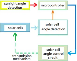
[image:3.612.143.472.241.503.2]The proposed "Vertical wall-to-light solar photovoltaic system" is to install solar panels on the walls of buildings, use the sunshine angle detection circuit to detect the sunshine angle, and send the sunshine angle data to the microcontroller circuit, after the microcontroller judges the message. The solar panel angle is determined, and the solar panel angle is detected by the solar panel angle detecting circuit, and then the solar panel angle control circuit is controlled, and the solar panel is detected by the motor to adjust the solar panel to the desired angle. The hardware structure diagram is shown in Figure 3.
Figure 3: Vertical wall type solar photovoltaic system hardware structure diagram
The functions of each component are explained as follows:
1. Solar panels: The function of solar cells with an additional mechanism that can control the angle, and wire them to the load system to be powered.
2. Sunlight angle detection circuit: It consists of a plurality of photodetectors at different positions. Different light detectors detect the difference in light intensity and determine the angle of sunlight. Because the sunshine intensity is different times, it is the difference between the light intensity ratio at different positions, not the difference between the light intensity and the weak value.
3. Solar panel angle detection circuit: Because the solar panel is installed outdoors, the angle of the board will be affected by some external factors, so the angle of the solar panel must be monitored, so an angle detection circuit is added to the solar panel.
4. Solar panel angle control circuit: A mechanism that controls the angle of control on the solar panel by a motor to turn the solar panel to the desired angle.
5. Microcontroller circuit: The main control circuit for monitoring the angle of the sun, monitoring the angle of the solar panel, and controlling the angle of the solar panel. The microcontroller we chose is the Holtek HT66F50 system microcontroller.
Figure 4: Vertical wall-to-light solar photovoltaic system control program flow chart
First, the sunshine angle detection circuit and the solar panel angle detection circuit input the sunshine angle and the solar panel angle data, and the microcontroller determines whether the solar panel angle needs to be adjusted and adjusted, and outputs a control signal to the solar panel angle control circuit to control the solar panel to change the angle. If there is no special break command, repeat the above process. The complete program content is shown in the appendix.
Figure 5: Overall composition block diagram
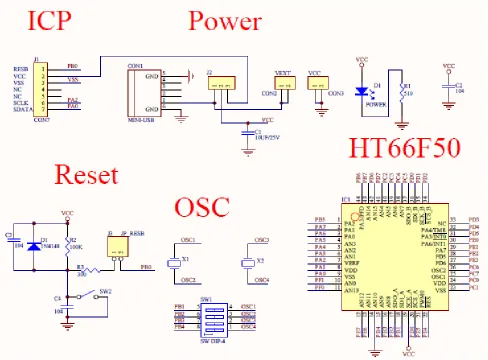
[image:5.612.67.555.159.519.2]In Figure 6, VSS is the 14th pin of the HT66F50, which is the grounding pin of the circuit. VDD is the HT66F50 pin 19, the power pin needs to be connected to 5V. The oscillating circuit uses an internal oscillating circuit, so there is no need to connect an external oscillating circuit. We use two 0.1uf capacitors (C1, C2) to make the HT66F50 The HXT oscillator circuit has a frequency of 1MHz. Figure 6 shows the reset circuit. VSS is pin 14 of the HT66F50 and is the ground pin of the circuit. VDD is the HT66F50 pin 19, the power pin needs to be connected to 5V. The oscillating circuit uses an internal oscillating circuit, so there is no need to connect an external oscillating circuit. We use two 0.1uf capacitors (C1, C2) to make the HT66F50 The HXT oscillator circuit has a frequency of 1MHz.
Figure 6: Reset circuit connection diagram of HT66F50
The 19th and 20th pins of the HT66F50 are reset circuits as shown in Figure 6. The reset circuit requires a 300-ohm resistor (R2), 41K ohm resistor (R1), IN4148, and two 0.1uf capacitors (C1, C2). The external adjustment button is added to the part. As shown in Figure 7, the 5th, 6th, 7th, and 8th pins of the HT66F50 are I/O positions. Since the voltage of the HT66F50 is too small, we add a ULN2803 circuit to increase the output voltage to the 12V. I/O pin is output from the ULN2803 Darlington circuit and then output from the 18th, 17th, 16th, and 15th pins of the ULN2803 via the 12V.
Figure 7: PD0 to PD4 pin connection of HT66F50 ULN2803 and stepper motor
Figure 8: Photosensitive detection board
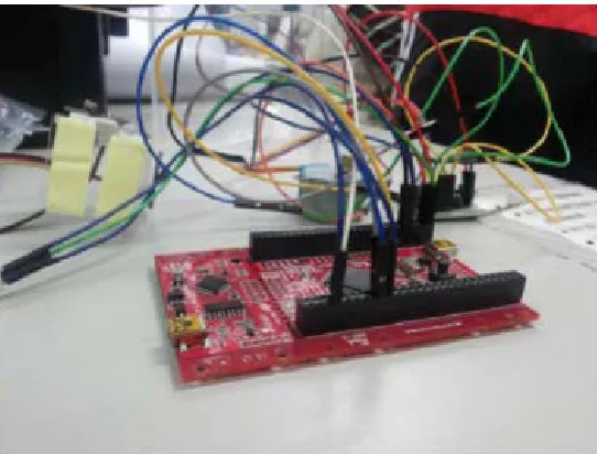
[image:6.612.171.442.489.695.2]Figure 10: The finished wall-to-light circuit
IV. CONCLUSION
The solar photovoltaic energy is a renewable energy source and used more and more widely. This implementation of proposed circuit combines this modern trend, using a photodetector to detect the sunshine angle and send the sunshine angle data to the microcontroller. After judging the message, it is determined that the solar panel angle control motor will be adjusted to the desired angle. In order to meet the needs set by the user, the signal is output to the stepping motor, so that the characteristics of adjusting the motor to adjust the solar panel to the desired angle in an automatic manner can be achieved as a useful reference for another researchers.
REFERENCES [1] N. Hiroshi, H. Masamitsu, S. Toshiaki, New York: McGraw-Hill Book Co. (2001) [2] M.A. Green, Physica, Vol.E 14, (2002), p11
[3] A.Wang, J. Zhao and M.A. Green, Appl. Phys. Lett., Vol.57, (1990), p602 [4] M.A. Green and K. Emery, Prog. Photovolt., Vol.2, (1994), p27
[5] J. Macneil, Proc., 10th Euro. Photovolt. Sol. Energy Conf. 1188 (1991)
[6] K.F. Yarn, W.J. Luo, W.C. Chang and W.C. Chuang, Inter. J. Phys. Sci., Vol.4, (2009), p758
[7] W.C. Chang, W.C. Chuang, C.T. Ho and K.F. Yarn, Digest Journal of Nanomaterials and Biostructures, Vol.1, (2006), p11 [8] G.C. Lin, L. Wang, C. C. Yang, M.C. Shih, T. J. Chung, IEEE Photonics Technology Letters, Vol.10, (1998), p406 [9] H.J. Eicher, P. Gunter and D.W. Pohl, Springer-Verlag (1986)
AUTHORS
First Author – Kao-Feng Yarn, Associate professor, Far East University
APPENDIX
[A] Program of solar angle driver
#include "arminno.h" #define Motor1 PB0 #define Motor2 PB1 #define Motor3 PB2 #define Motor4 PB3
void stepmotorp12f(int i,int k); void stepmotorp12b(int i,int k); int main(void) { u16 lm1,lm2,lm1m,lm2m,stepstate,steptg,step001; u8 cc; stepstate=90; steptg=90; SetAdc(6);//PA6 SetAdc(7);//PA7 cc=0;
Output(Motor1); Output(Motor2); Output(Motor3); Output(Motor4); while(1)
{
// Read light sensor value
lm1=GetAdc(6); lm2=GetAdc(7);
lm1m=lm1/64; lm2m=lm2/64; cc=1;
// Compare two photo sensor values to determine the angle if((lm1m>(10*lm2m))) {steptg=100; } else if((lm2m>(10*lm1m))){ steptg=200;} else { steptg=150; if((lm1m>(6*lm2m))) steptg=110; if((lm1m>(4*lm2m))) steptg=120; if((lm1m>(3*lm2m))) steptg=130; if((lm1m>(2*lm2m))) steptg=140; if((lm2m>(2*lm1m))) steptg=160; if((lm2m>(3*lm1m))) steptg=170; if((lm2m>(4*lm1m))) steptg=180; if((lm2m>(6*lm1m))) steptg=190; }; if(stepstate>200) stepstate=200; if(stepstate<100) stepstate=100;
www.ijsrp.org { if ((steptg>stepstate)) { stepmotorp12b(20,13); Pause(2); stepstate=stepstate+10; }
else if ((steptg<stepstate)) { stepmotorp12f(20,13); Pause(2); stepstate=stepstate-10; } else { cc=10; }; }; Pause(1000); } }
// Stepper motor driver 1-2 phase
void stepmotorp12f(int i,int k) { int j; for(j=0;j<i;j++){ High(Motor1);Low(Motor2);Low(Motor3);Low(Motor4);Pause(k); High(Motor1);High(Motor2);Low(Motor3);Low(Motor4);Pause(k); Low(Motor1);High(Motor2);Low(Motor3);Low(Motor4);Pause(k); Low(Motor1);High(Motor2);High(Motor3);Low(Motor4);Pause(k); Low(Motor1);Low(Motor2);High(Motor3);Low(Motor4);Pause(k); Low(Motor1);Low(Motor2);High(Motor3);High(Motor4);Pause(k); Low(Motor1);Low(Motor2);Low(Motor3);High(Motor4);Pause(k); High(Motor1);Low(Motor2);Low(Motor3);High(Motor4);Pause(k); }; };
[B] Program of stepper motor driver
// PROGRAM : 4-6.c
// FUNCTION : STEP MOTOR HALF STEP CONTROL #include "HT66F50.h"
#define Motor_Port _pe #define Motor_PortC _pec
const unsigned short TAB_CW[] = { //Excitation Table 0b0001,0b0011,0b0010,0b0110,
0b0100,0b1100,0b1000,0b1001}; void main()
{ short i,j;
Motor_PortC=0x0; //Config Port as O/P Mode
while(1)
{ for(i=0;i<50;i++)
{ for(j=0;j<8;j++)
{ Motor_Port=TAB_CW[j]; //Read Table
_delay(10000); //Delay 10mS
} }
for(i=0;i<50;i++) { for(j=7;j>0;j--)
{ Motor_Port=TAB_CW[j]; //Read Table
_delay(10000); //Delay 10mS
} }