Methods to improve the PVD coatability of brass by using
diffusion barriers.
LANGER, Bernd.
Available from Sheffield Hallam University Research Archive (SHURA) at:
http://shura.shu.ac.uk/19940/
This document is the author deposited version. You are advised to consult the
publisher's version if you wish to cite from it.
Published version
LANGER, Bernd. (1995). Methods to improve the PVD coatability of brass by using
diffusion barriers. Masters, Sheffield Hallam University (United Kingdom)..
Copyright and re-use policy
See
http://shura.shu.ac.uk/information.html
SHEFFIELD HALL AM UNIVERSITY USHAHY CiTY CAMPUS POND STREET
SHEFFIELD Si 1WB
Sheffield Hallam University
REFERENCE ONLY
ProQuest Number: 10697246
All rights reserved
INFORMATION TO ALL USERS
The quality of this reproduction is dependent upon the quality of the copy submitted.
In the unlikely event that the author did not send a com plete manuscript and there are missing pages, these will be noted. Also, if material had to be removed,
a note will indicate the deletion.
uest
ProQuest 10697246
Published by ProQuest LLC(2017). Copyright of the Dissertation is held by the Author.
All rights reserved.
This work is protected against unauthorized copying under Title 17, United States C ode Microform Edition © ProQuest LLC.
ProQuest LLC.
789 East Eisenhower Parkway P.O. Box 1346
Methods to improve the PVD coatability of brass by using
diffusion barriers
Dipl.-lng. (FH) Bernd Langer
A thesis submitted in partial fulfilment of the requirem ents of
Sheffield Hallam University
for the degree of M aster of Philosophy
S eptem ber 1995
Collaborating Organisations:
This thesis is submitted to Sheffield Hallam University for the degree o f Master o f Philosophy.
The research was carried out during the period from September 1994 to September 1995 at the Materials Research Institute at the Sheffield Hallam University.
Post graduate courses in Crystallography, Electron microscopy and X-Ray techniques I and Surface Engineering I (PVD hard coatings) were attended at the Materials Research Institute at Sheffield Hallam University.
The results obtained during the course of this work are to the best of my knowledge
original, except where reference is made to other work.
-This thesis or any part, has not been submitted for a degree at any other university.
Contents
(i) Abstract Englisch... i
German... ii
(ii) Acknowledgements... iii
1) Introduction, Aims and Objectives... 1
2 ) Literature Review... 3
2.1 ) Substrate and Coating Materials... 3
2.1.1) Substrate... 3
2.1.2) Brasses... 3
2.1.2.1 ) Structure... 4
2.1.2.2) Mechanical Properties... 4
2.1.2.3 ) Hot Forming Abilities... 4
2.1.2.4 ) Cold Forming Abilities... 5
2.1.2.5) Recrystallisation... 5
2.1.2.6) Cutting Properties... ... 5
2.1.3 ) Used Brass Substrate, Properties and Softening Behaviour .. 6
2.1.4 ) Evaporation of Zinc (Zn) Under Vacuum... 8
2.1.5) Coatings... 9
2.1.5.1 ) Intermediate Barrier Layers... 9
2.1.5.1.1 ) Diffusion Barrier... 10
2.1.5.1.2 ) Corrosion Resistance... 11
2.1.5.1.3) Appearance... 12
2.1.5.2 ) Electroplated Intermediate Layers... 15
2.1.5.3) PVD Intermediate Layers... 18
2.1.5.4 ) Used PVD Layer Systems... 18
2.1.5.4.1 ) Aluminium (A l)... 18
2.1.5.4.2) Niobium (N b)... 18
2.1.5.4.3 ) Aluminium-Niobium (Al-Nb) Sputter A lloy... 19
2.1.5.4.4 ) Copper-Aluminium (Cu-Al) A lloy... 19
2.2) Principles of Corrosion... 21
2.2.1) Theory of Corrosion... 21
2.2.2 ) Corrosion of PVD Systems... 22
2.3) Principles of Diffusion... 24
2.4) Physical Vapour Deposition... 26
2.4.1 ) Coating Deposition from Vapour Phase... 26
2.4.2 ) Physical Vapour Deposition PV D ... 27
2.4.3) Coating Methods... 28
2.4.4) Magnetic Field... 30
2.4.4.1) Magnetic Fields on the Target... 30
2.4.4.1.1 ) Balanced and Unbalanced Sputtering Systems... 30
2.4.4.1.2) Random and Steered A rc... 31
33 33 34 36 36 37 37 38 40
41
43 43 45 4951
52 53 55 55 57 57 58 60 60 60 60 61 62 62 63 63 63 65 6566
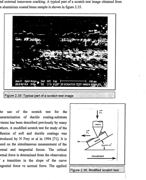
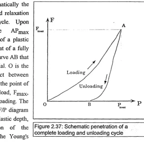
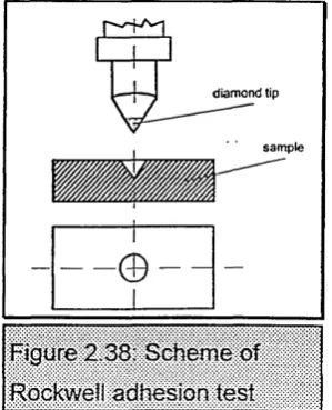
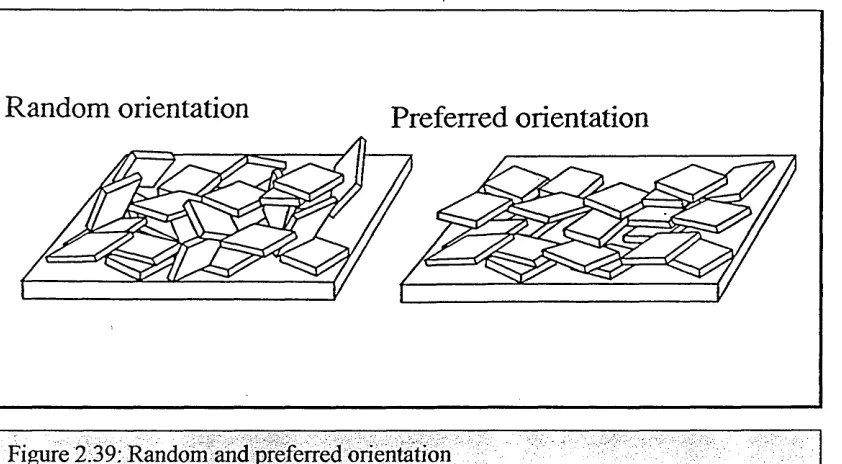
67 69 70 72 74 77 78 78 79 79 79 The HTC 1000-4 ABS ™ ... The Vacuum Chamber of the ABS™ System... The Cathods... Target and Substrate Cleaning in the PVD Chamber... Target Cleaning... Substrate Cleaning... Argon Glow Discharge M ode... Metal Ion Etching M ode... ... Coating in the PVD Chamber... Coating Growth and Structure Zone M odels...Test Methods ... Glow Discharge Spectroscopy... Adhesion and Scratch T est... Hardness... Indentation Adhesion Test... X-Ray Diffraction... Corrosion Tests...
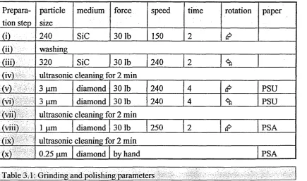
Experimental Techniques... Diffusion T est... Sample Preparation... Grinding and Polishing... Precleaning... Cleaning in the PVD Chamber... Argon Ion Etching... Metal Ion Etching... Combinded Argon and Metal Ion Etching... Coating Processes... Aluminium Diffusion Barrier (A l)... Aluminium-Niobium Diffusion Barrier (Al-Nb(X))... Copper-Aluminium Diffusion Barrier (CuA18)... Copper-Aluminium-Niobium Diffusion Barrier (CuA18-Nb(X)) Niobium Coatings (N b)...
4 ) Results... 80
4.1) Diffusion Test of Uncoated Brass Substrate... 80
4.2 ) Precleaning of the Brass Substrate... 81
4.3 ) Cleaning in the PVD Chamber... 82
4.3.1 ) Argon Ion Etching... 82
4.3.2 ) Metal Ion Etching... 82
4.3.3 ) Combined Argon and Metal Ion Etching... 83
4.4) Coating Processes...,... 84
4.4.1) Aluminium Diffusion Barrier (Al)... 85
4.4.2 ) Aluminium-Niobium + Niobium (AlNb(X)+Nb)... 89
4.4.3 ) Copper-Aluminium Diffusion Barrier (CuA18)... 92
4.4.4 ) Copper-Aluminium-Niobium + Niobium (CuA18Nb(X)+Nb) 95
4.4.5 ) Niobium Coatings (Nb) ... 99
5 ) Discussion... 103
Conclusions... 107
References... 108
6 ) Figures and Tables... 114
Appendix... 170
Product Data Sheet Henkel P3 Galvaclean 6 2 ... 171
Product Data Sheet Henkel RST... 172
EXCEL Work Sheet (XRD)... 178
ABSTRACT
Previous work involving PVD coatings on brass has used a combination of multilayers consisting o f electroplated films like nickel or chromium and deposited decorative PVD coatings like TiN, TiAIN or ZrN systems. The disadvantages of these systems are the combination o f wet electrochemistry and high tech vacuum processes. Furthermore the allergic reaction to nickel and the toxic nature of Cr(VI) must be considered.
There is a need for intermediate layers to 'seal-off the brass in order to avoid the evaporation of zinc in vacuum using a diffusion barrier. Furthermore the intermediate layers are required to act as a corrosion barrier.
This thesis reports on the development of PVD coatings on heat sensitive brass substrate materials utilising ABS™ technology with Al, CuA18 and Nb targets as vapour sources.
The brass pretreatment includes careful grinding, polishing and cleaning steps as well as steered arc metal ion etching using the above target materials. The coatings are produced at temperatures between 100 and 250°C in the unbalanced magnetron mode, including layers made from Al, Al-Nb, CuA18, CuA18-Nb and Nb.
Scratch adhesion and Rockwell indentation tests are found not to be directly applicable to the system o f soft brass and ductile coating(s). Therefore a new classification for both scratch and indentation tests was defined. The best adhesion was shown by the CuA18 coatings on brass. Corrosion tests showed good results for the Al coatings and poor results for the pure Nb coatings directly applied on brass. The best corrosion result was obtained with a CuA18-Nb layer system. This layer system also offers veiy good barrier behaviour concerning Zn diffusion.
Zusammenfassung
PVD-Schichten auf Messing werden bisher durch Kombination von galvanischen Zwischenbeschichtungen wie Nickel oder Chrom und dekorativen PVD-Schichten wie TiN, TiAIN oder ZrN hergestellt. Der Hauptnachteil liegt in der Kombination von naBchemischen Techniken und 'high-tech' Vakuumprozessen. Weiterhin miissen heutzutage die Allergieprobleme durch Nickel und die Toxizitat von Cr(VI) in Betracht gezogen werden. Mit den Zwischenschichten wird das Messing versiegelt, um eine Zinkausdampfung bedingt durch den Zinkdampfdruck im Vakuum durch eine Diffusionsbarriere zu verhindem. Weiterhin dienen die Zwischenschichten als Korrosionsbarrieren zwischen dem unedlen Substratwerkstoff Messing und den zum Teil sehr viel edleren dekorativen Schichten wie z.B. Niob. Niob selbst zeichnet sich durch eine hervorragende Korrosionsbestandigkeit aus.
Diese Arbeit berichtet von der Entwicklung von PVD-Schichten auf temperaturempfindlichen Messingsubstraten hergestellt durch die ABS™ (Arc-bond-sputtering) Technologie. Die verwendeten Beschichtungsquellen sind Al, CuA18 und Nb Targets.
Die Messingvorbereitung umfasst sorgfaltiges Schleifen, Polieren und Reinigen, wie auch 'steered arc' Metall-Ionen Atzen mit den oben genannten Targetmaterialien. Die Schichten wurden im Temperaturbereich zwischen 100 und 250 °C mithilfe des unbalancierten Magnetrons abgeschieden. Die produzierten Schichten umfassen Al, Al-Nb, CuA18, CuA18-Nb und reines CuA18-Nb.
Es stellte sich heraus, daB der Ritz-Adhasionstest und Rockwell-Eindrucktest nicht direkt bei dem System »weiches Messing« und duktile Schichten angewendet werden konnen. Deshalb wurde eine neue Klassifizierung fur den Scratch- und Rockwell-Test defmiert. Die beste Adhasion zeigten die CuA18-Schichten. Korrosionstests zeigten gute Ergebnisse fur die Al-Schichten und schlechte Ergebnisse fur direkt aufgebrachte Nb-Al-Schichten. Das beste Korrosionsergebnis zeigte ein CuA18/Nb-Schichtsystem. Diese Kombination wies auch hervorragende Eigenschaften als Diffusionsbarriere gegen die Zinkausdampfung auf.
Acknowledgements
I would like to thank my Director of Studies and Supervisor Prof. Dr. W.-D. Mtinz for his advice and encouragement.
I would like to thank Dr. Bogel, Mr H.-K. Knirsch and Mr R. Koch of Wieland-Werke AG for the commitment and advice concerning brass materials.
I would also like to thank Prof. Dr. Bergner of Freiberg University for advice concerning diffusion in brass materials.
Special thanks go to Mr. W. Kalb of Gesellschaft fur Elektrometallurgie mbH for the CuA18 target.
A veiy special thanks goes to Simon Yakan, who tried to show me the differences in English English and German English and polished my thesis.
The author would like to thank everyone who has been involved in the work towards this thesis, particularly the staff o f the Materials Research Institute at Sheffield Hallam University.
1.0 Introduction
Maslow [1] defined the needs of human beings and developed the so called »satisfaction of needs pyramids He found that mankind first has to substantiate fundamental desires like eating, drinking and reproduction. After these three basic needs people tiy to maintain their level of comfort, claim a place to cultivate and grow plants and keep animals. People already had cult objects for ritualistic acts. They were largely made from gold and bronzes. Nowadays, peoples' life styles are characterised in industrial countries by guaranteed feeding, long life expectancy and good leisure amenities. It is now, even more, that the need arises for decorative articles, like jewellery, watches and other consumer goods.
The aim of the consumer goods industry is to produce valuable and valuable looking products, even for daily life. These increasingly competitive conditions placed demands on companies for advanced technologies. Contrary to the production of goods made from elements like gold, silver and titanium there are the methods of using cheaper substrate materials in combination with decorative ennoblement. A good example is the use of brass materials with applied electroplated coatings. Considering the rise of human illnesses like nickel allergy and excited by the growing demand of better coatings made with newly available coating techniques, physical vapour deposited (PVD) coatings are favourite candidates for the production of such decorative coatings. PVD refers to a class of plasma based coating techniques. Metals, alloys or chemical compounds are transferred into the vapour phase by thermal energy or particle bombardment in a high vacuum and condense onto the substrates. Using the PVD technique, not only decorative but also functional coatings can be produced. Important representatives of this family are corrosion barriers, wear resistant and hard coatings as well as high temperature coatings. It is important to optimise functional and aesthetic properties like resistance to corrosion, resistance to wear, good coating adhesion, control of colours and to avoid allergic reactions. Decorative coatings on brass find their applications in watch cases, spectacle frames, engineering components for use in videos and photographic apparatus, precision components in electromechanical applications and the writing tool industry. Physical vapour deposited (PVD) coatings are now being used in many sectors of industry on account of both their favourable wear and decorative properties [2, 3]. Thus hardwearing, gold coloured titanium nitride (TiN) coatings are widely used in the advanced machine tool industry on account of their wear properties and in the horological industry in the manufacture of good quality watches on account of their aesthetic appearance.
PVD coatings applied directly on brass is due to, (i) evaporation of zinc from the brass surface and (ii) the formation of zinc oxide at the substrate / coating interface during the course of the coating process.
The conventional approach to solving the problem is to "seal o ff’ the brass surface using an electrodeposited coating. Coatings which have been used for this purpose include chromium, nickel and nickel-palladium deposits as well as duplex copper-nickel coatings [4, 5]. Unfortunately, the use of all these have some unfavourable aspect: Electroplated chromium is to be avoided from an environmental point of view as is that o f nickel on account of its adverse allgenic properties. The use of electroplated copper has two drawbacks since when used alone it does not provide appropriate surface for PVD coatings and its use can lead to the diffusion of zinc from the brass substrate into the coating with the resulting formation of brittle copper-zinc intermetallic compounds. The intermetallics can then cause poor adhesion of the PVD coating.
An elegant solution to the problems associated with the use of PVD coatings on brass would be to form an intermediate barrier layer by the PVD process which would seal off the brass surface and prevent zinc diffusion from the substrate. This would not only solve the adhesion problem but eliminate the use of environmentally unfriendly wet electroplating steps. Two possible barrier coatings obtainable using PVD process appear worthy of consideration, either a thin aluminium or a copper-aluminium coating. The latter has the additional advantage that it has a gold colour when formed with the appropriate composition and might therefore act as a decorative coating on its own right.
Using the above approach it should be possible to develop multilayer coatings suitable for decorative purposes which could be formed on small 60:40 brass components. Typical coatings which might be fomed using such a multi-stage process include Al/Nb, AlNb/Nb, CuA18/Nb, CuA18Nb/Nb and Nb coatings. The use of such decorative coatings would be subjected to their meeting the usual corrosion and compatibility tests associated with the particular sectors of industry where they are to be used, for example in watch and jewellery manufacture [6, 7].
v j u u o i i v r \ i i / - \ i vvj i i i n ' j i v i / a i l i a i / a l
CHAPTER 2: Literature Review
2.1 Substrate and Coating Materials
Decorative hard coatings can be produced in various colours. The colour systems used are for example CrNx (metallic grey), TiNx (light yellow - gold colour - brownish yellow), TiCxNy (gold colour - reddish brown, adjustable to any gold colour tone), TiAIN (anthracite) and TiZrNx (golden colours) [2]. To solve the natural tarnishing problem of brass, which leads to a decreasing reflectance, decorative ZrN coatings are used to obtain brass colours [8]. These decorative coatings have a high hardness, so that a coating thickness of 0.5 to 1 pm is sufficient to obtain the same life time as that obtained from a 20 pm thick electroplated gold coating [11], Applying a coating that always contains pores and pinholes on a substrate means that the corrosion behaviour must be considered, especially if the potential difference is large.
2.1.1 Substrate
Decorative coatings on corrosive resistant substrate materials like titanium or austenitic chromium-nickel steels have been well known for years. These substrate materials have the disadvantage of extreme hardness, making it difficult to machine them like drilling, milling, grinding or polishing. The build-in of surface structures is extremely complex and makes it not economically viable. It is desirable to use soft substrate materials for better teeming, machining and surface finishing, although it is less corrosion resistance [9, 10]. Brass itself is softer than particles of dust [11] and is, without manipulation not usable for decorative purposes, but the surface properties are independent of the volume properties if a coating is applied.
2.1.2 Brasses (Cu-Zn Alloys)
2.1.2.1 Structure
Figure 2.1: Structure of an a-brass, 100 x Figure 2.2 : Structure of a (3-brass, 100 x
A closer look at the Cu-Zn phase diagram (figure 6.57c) shows the increasing solubility for Zn in the fee a-solid solution crystal. The bcc (3-mixed crystal changes into the P'-phase below 460 °C. The cubic y-P'-phase is very brittle. The 5-, s- and rj-P'-phases have a hexagonal lattice like pure Zn. Due to the brittleness of the brasses with the appearance of the y-phase only alloys up to 50 % Zn are technically used. We distinguish the a-brasses (figure 2.1) with straight limited polygons and twinning bands and the p-a-brasses (figure 2.2) with no twinning bands.
2.1.2.2 Mechanical Properties
With increasing Zn content in the a-area the tensile strength and hardness increases slightly, whereas the ductility increases greatly. Contrary to this the tensile strength and hardness increases with the appearance of the P-phase, but the ductility decreases. The highest tensile strength is for pure P-brass.
2.1.2.3 Hot Forming Abilities
If the Pb concentration is less than 1 % in an (a+P)-brass and less than 0.02% in an a-brass the hot forming ability is very good. The reason for this is that p-mixed crystals can accommodate up to 1 % Pb whereas the a-mixed crystals can only hold a minimal amount. Hence the Pb is at the grain boundaries of a-brasses and makes it brittle at deforming temperatures above 329 °C. Forming under pressure' from all sides like impact forging or extrusion moulding, the lead concentration has less influence. Bi, which is not at all soluble in a-brass makes hot forming impossible at a concentration of 0.005%.
2.1.2.4 Cold Forming Abilities
(a+p)-brass is not suitable but a-brass is very suitable for cold forming. The tensile strength increases greatly much but the ductility decreases significantly. For example the breaking elongation decreases in a cold forming process of a CuZn37 F 30 (Rm = 300 N/mm.2) via the half hard and the hard into the spring hard condition from 45 % to
2
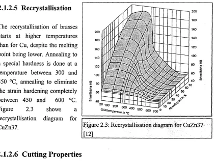
%.2.1.2.5 Recrystallisation
[image:16.623.103.524.180.504.2]The reciystallisation of brasses starts at higher temperatures than for Cu, despite the melting point being lower. Annealing to a special hardness is done at a temperature between 300 and 450 °C, annealing to eliminate the strain hardening completely between 450 and 600 °C.
Figure 2.3 shows a
reciystallisation diagram for CuZn37.
2.1.2.6 Cutting Properties
Brasses are very suitable for rapid machining. (a+P)-brasses are more suitable for rapid machining than P-brass. Only 0.01 % Pb leads to an improvement o f the cutting property of a-brass, but deteriorates the hot forming properties. To make the removal o f material on automates easier, up to 3 % Pb is alloyed into a- and (a+P) -brasses. The finer the distribution of Pb, the better the effect.
200 180 160 200 140 180 120 160 100 140 120 60 100 40 70 50 40 20
20 100 2o03oT Tvr^^-C j
Gmtenpenturin°c 600 600 700
Figure 2.3: Recrystallisation diagram for CuZn37
[
12
]
:
• w v * - / v _ / • I v # \ I I / - i M L y v v r v I 1 1 N V J I V l / ~ V I I I \ I / ~ V 1 —
2.1.3 Used Brass Substrate, Properties and Softening Behaviour
The substrate used in this work is 60:40 brass. The analysis was done using the X-Ray Fluorescence method (XRF) on a Philips PW2400 [14]. The result is shown in table 2.1.
element Cu Zn Pb Sn Ni Fe Mg
conc. in mass % 61.6 36.52 1.52 0.103 0.06 0.17 0.015
Table 2.1: Analysis of the brass substrate
From the analysis this material can be recognised as CuZn36Pbl.5*, which is equivalent to the UK BS CZ118 / material number 2.0331 / USA UNS Nr. C34000**. The following properties are typical for this brass [12] (tables 2.2, 2.3 and 2.4):
Characteristic Quantities Condition
soft half hard hard spring hard
tensile strength Rm [N/mm^l 340 400 490 550
tensile yield strength [N/mm^l 130 300 450 520
elongation Ai o [%1 50 30 12 3
hardness HB 75 115 140 160
shearing strength [N/mm?] 250 300 330
notched bar impact value [J/cm^] 47
[image:17.615.80.529.231.653.2]modulus of elasticity [fkN/mm^] = 110 moc ulus of torsional shear [kN/mm^] = 39
Table 2.2: Mechanical properties [12]
density [g/cm^] 8.45
melting range [°C] 902-915
electrical conductibility
fm/Qmm^] 14.7
average temp, coeff. of electrical
resistance [K"^l 0.0014
caloric conductibility fW/mK] 113
thermal expansion coeff.
[10-6/K] 20.4
hot forming ability good
cold forming ability good
cutting property index
(CuZn39Pb3 = 100) 80
polishable good
electroplateable very good
soft solderable very good
hard solderable moderate
weldability
gas qualified
inert gas qualified
resistance moderate
soft annealing temp. [°C1 450-650
relaxation temp. [°C1 200-300
hot forming temp. [°C1 750-800
Table. 2.3: Physical properties Table. 2.4: Treatment properties
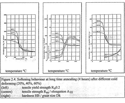
This described alloy is mainly used if there is the need for metal removal and non cutting shaping like pressing, bending or imprinting. Figure 2.4 shows the softening behaviour after cold deforming.
temperature °C temperature °C
[image:18.629.92.524.125.481.2]temperature °C
Figure 2.4: Softening behaviour at long time annealing (4 hours) after different cold deforming (20%, 40%, 60%)
(left) tensile yield strength Rn0.2
(centre) tensile strength / elongation A^o
(right) hardness HB / grain size Dk - ,
At temperatures greater than 250 °C to 300 °C all properties change dramatically. The hardness will increase to a maximum until this point, whereas Rm and Rp0.2 decreases slowly, afterwards rapidly to a minimum.
2.1.4 Evaporation of Zn Under Vacuum
The vapour pressure of Zn has been studied by several investigators and summarised by
Cominco (1956) and a simple empirical equation developed [15].
Ig (p /1.33322)= ( -6888/T ) + 8.888 ... 1)
with vapour pressure p in mbar and temperature T in K.
Under conditions of high vacuum (10"5 to 10"6 mbar), metals begin to evaporate rapidly when the temperature rises to the point where the vapour pressure is higher than approximately 10“2 mbar [16]. The Zn vapour pressure at 200 °C is calculated with equation 1 to 2.79x10~6 mbar. Figure 2.5 shows the vapour pressure of several metals as a function of temperature. During the evaporation process, in equilibrium conditions, molecules are continuously passing from the condensed phase to the vapour phase, but at the same time, another stream of molecules is condensing out of the vapour and the two processes balance each other [16,17].
Tem perature d egrees Celsius
-150 -100 -50 0 50 100 300 600 1000 2000 3000
o
a> H |0
/ /
.-6
100 200 600 800 1000 2000 3000 4000
[image:19.613.128.480.348.618.2]Tem perature deg rees kelvin
Figure 2.5: Vapour pressure data for several materials [16]
2.1.5 Coatings
Decorative electroplated coatings are classified in a guideline of the "Deutsche Gesellschaft fur Galvano- und Oberflachentechnik" [18]. The requirements include the corrosion resistance, wear and coating thickness. Up to now there are no guidelines available for hard decorative coatings, but these films have to cope at least with the electroplated alternative [19]. In contrast to electroplating processes, when coating three dimensional products by PVD there are problems with the microstructure and associated properties like colour, density and adhesion caused by different angle-of-incidence flux effects [20], This problem can be partly overcome by substrate rotation (1 to 3 fold rotation).
Coatings applied on substrate surfaces can be distinguished as intermediate layers and decorative layers on top. Interesting PVD coatings for investigation are the carbides, nitrides and oxides of certain elements of the fourth to the sixth group of the periodic table of the elements, e.g. Ti, Zr, Hf, Nb, Ta, Cr, W and their alloys [9, 21]. The coating properties differ between bulk-, powder- and sputter alloys.
Decorative hard coatings are characterized by the following properties [2]: (i) controlled final colours (reproducible, uniform colour tone)
(ii) resistance to wear (iii) resistance to corrosion (iv) cost effectiveness
In an ideal situation of hard decorative coatings there is no need for an intermediate layer. But to get coatings with low pore concentration and sufficient adhesion, multilayers are required. The single coatings have special functions such as: improvement of the adhesion, diffusion barrier, smoothing the surface, appearance [22], compensation of various thermal expansion coefficients and corrosion barrier [23].
2.1.5.1 Intermediate Barrier Layers
PVD coatings may not be applied directly to Zn or Cd containing substrate materials, because of the high vapour pressure of these elements. Therefore there is the need for intermediate barrier layers to vacuum thight seal these elements [24].
The intermediate barrier layer must have the following properties, which are explained below:
- diffusion barrier for Zn and Pb
- minimum o f pores
- integrity o f the corrosion resistance o f the entire system - low cost
- no allergenic reaction
- appropriate for following PVD processes [6]
- adhesion of the undercoating to the substrate material
- mechanical accommodation of the system PVD-layer / intermediate layer / substrate [9]
2.1.5.1.1 Diffusion Barrier
As already mentioned, one function of barrier layers is the prevention o f diffusion. When coating brass by PVD there is the need for a diffusion barrier, because brass is a heat sensitive material Interdiffusion occurs between base materials and the coating, resulting in the formation of intermetallic compound layers. Mainly in storage and operation, harmful elements, such as Zn, diffuse from the brass substrate to the coating and change the composition. The presence of Zn at the surface results in the formation of atmospheric corrosion products. The induced oxide films upon the surface affect properties, resulting in poor adhesion and discolouration of coatings directly deposited to brass. Consequently an intermediate barrier layer is used as a diffusion barrier to minimise this effect [25]. The deleterious effect of Zn diffusion can be reduced by thicker coatings as intermediate layers which inhibit diffusion [26].
An ideal diffusion barrier should avoid the interdiffusion between the brass substrate and the decorative top layer and should neither interact with the substrate material nor with the coating. The aims o f a diffusion barrier layer are:
(i) to avoid extreme diffusion zones [27]
(ii) to reduce the the rate of growth of interfacial compound layers [25] (iii) to reduce the extent o f diffusion into a coating [25]
(iv) to avoid pores caused by the Kirkendall effect at high temperatures [27]
In reality there is always diffusion o f substrate and coating material into the diffusion barrier and diffusion of the barrier layer material into the substrate and coating -depending on the diffusion barrier itself, the diffusion coefficients, the exposure time and temperature.
To act as a diffusion barrier, the barrier layer material should have the following properties
(i) a high melting point compared to the diffusant
(ii) a dense structure, if possible fee or hex with an atomic packing density of
R. Pinnel et al [28] investigated the mechanism of diffusion barriers by qualitative evaluation of frequently used nickel layers. Results demonstrated that the nickel layer retards but does not block the transport of the substrate material to the top coating. They found that the effectiveness of Ni in retarding the out-diffusion of Cu to an Au surface has its basis in the miscibility gap within the Au-Ni system. This restricted range of solid solubility which limits the concentration increase of Au in Ni and vice versa significantly affects the interdiffusion behaviour. The time necessary to diffuse Cu to the Au surface at a given temperature is longer with the Ni layer than without it. Finally, increasing the nickel thickness increases the time necessary for Cu penetration to the surface.
The reason for the miscibility gap within the system Au-Ni is the difference in the lattice parameter of 13.6 %. The limit of lattice parameter differences is ± 14% [29], given by lattice stresses resulting in elongation and contraction caused by smaller or bigger substituted atoms. This effect increases with higher concentrations of the alloyed atoms. There is also an influence of the valence to the formation of mixed crystals and miscibility gaps.
2.1,5.1.2 Corrosion Resistance
2.1.5.1.3 Appearance
The appearance of the coatings is especially important for decorative purposes. This is mainly influenced by the substrate itself, the preparation including precleaning and the coating process, since it is reported that PVD coatings directly applied on brass have a matt apearance.
(i) substrate: To get the good quality surface necessaiy to produce valuable products, substrates made from special quality brasses (excluding recycled materials) are required. Recycled brass veiy often contains trace elements like Fe and Co, which lead to unsightly spots in electroplating and PVD. There is also the effect of the two brass phases a and p which are attacked differently by wet chemistry precleaning and ion etching processes, leading to a decreasing brilliance [20],
(ii) preparation and precleaning: Perfect substrate preparation and precleaning is essential for eveiy process. Scratches and impurities like greases, oils, machining-, grinding- and polishing residues, thin oxide layers, adsorbed carbon hydrides and dust are often the origin of faults and coatings with bad qualities like reduced adhesion and pores in the coating. Corrosion will occur preferentially at these places [22]. Also important is that with increasing roughness of the substrate surface the brightness is decreasing, and only on perfect polished surfaces an optimum of brillance is achievable [21]. Consequently there is the need for an individual precleaning program o f the substrate, because the adhesion between the coating and the metal surface depends mainly on the interface moiphology, the nucleation, chemical reactions and diffusion processes in the interface region. Generally alkaline baths serve for removal o f oils, greases and other organic residues, whereas acid baths serve to pickle and activate the surface as well as to neutralize the alkaline residues. Degreaser should not contain silicats or borats because of a possible formation of films on copper alloys [31]. Between all baths a rinsing in deionsed water is necessary to remove the residues o f the prior cleaning step.
l W 1VI/—\ I L.I \irV L V j
be a failure reason. Therefore it seems to be important that sharp cutting tools are used to machine the substrate in order to avoid any smearing of Pb. Furthermore, a pickle step should be included in the precleaning to get rid of smeared lead, using HNO3 or HBF4.
The atomiser test [22], which was described previously by K. Wittel in 1981, is able to examine the precleaning. The cleaned and cooled room temperature sample needs to be sprayed by an atomiser, until the surface is covered with a thin water film. Under the microscope small drops are visible, separated by smaller or bigger non wetted areas. Only if the entire area is covered with drops is the precleaning sufficient. At non wetted areas the activation of the surface is insufficient, leading to poor adhesion of the drops and the surface.
(iii) coating process: The structure to be obtained to get a shiny, bright surface is the transition zone T from the Thornton diagram. Hence it is important to investigate the appropriate process temperature depending on the applied bias voltage and chamber pressure (see chapter 2.4.8).
2.1.5.2 Electroplated Intermediate Layers
mechanical surface treatment
grinding, polishing, burnishing, blasting
precleaning electroplating
surface topography, bright plating, corrosion resistance
cleaning
________ PVD coating_________
Figure 2.6: Schematic combined process
Satisfying results for intermediate layers on brass are, up to now, only achievable using a combination of electro plated and PVD layers, if there is the need for shiny coatings on rough surfaces with a long life time [4, 22]. A typical schematic process of combined electroplated intermediate layer and PVD decorative hard coating is given in Figure 2.6. The samples have to be prepared mechanically,
followed by a wet precleaning. To produce a clean and active metal surface, the oxids, greases, dirt such as dust and residues from grinding and polishing must be eliminated. The methods used for degreasing and cleaning are organic solvents or water based cold- and hot detergents, followed by chemical or electrolytic degreasing procedures [9, 10]. A galvanic barrier layer has to be applied, followed by a cleaning step prior to the PVD coating process.
By electroplating, the surface structure can be changed in wide ranges, using the following features:
(i) the structure and coating composition is given by the electrolyte composition [6] (ii) the surface roughness can be smoothed having a rather thick coating on scratched
— — —’ w . ■ u t ■ *— # ii i w v ^ / % i i i i i ¥ u \ i i—i \a / x u v j
The main disadvantages of electroplated intermediate layers and the use for combined electroplating and PVD coatings are:
(i) Ni-coatings are passivating very fast, resulting in poor adhesion of PVD coatings
[
10
]
(ii) Electroplating processes can involve hazardous waste products
(iii) Electroplating combined with PVD is a multistage process, including wet chemistry and high vacuum technology.
(iv) Ni is known as a material causing allergical reactions.
(v) metastabile phases in coating systems can transform under heat influence, resulting in segregations and hence limiting the substrate temperature at a following process step [23],
Various types of electroplated intermediate layers were examined.
Ni: systems with hard coatings directly applied on Ni are not resistant for contact corrosion. Only at a coating thickness of around 20 pm are good results achievable. Having around 50 pm electroplated Ni the coatings become brittle, resulting in hte loss of the decorative appearance of the coating [3, 22]. Ni causes allergies even when it is beneath a gold layer or a PVD coating with pin-holes [5].
Currentless Ni-P: Improvements of the corrosion resistance were made using Ni-P coatings [23]. Ni with 9 to 13 % P results in an amourphous structure of the barrier layer [33].
Ni + Cr: The behaviour is improved compared to the pure Ni. The Cr extends the time between the electroplating and the following PVD process, but the fine crack work in the Cr film cannot be covered by the PVD coating [22, 3]. NiCr has no satisfying corrosion resistance.
Ni + Au: This system has an excellent corrosion behaviour at an Au coating thickness o f 1 to 2 pm. The main disadvantages are the very high costs and the bad mechanical behaviour of the soft gold film to the hard PVD coating [22].
Ni + Pd/Ni: excellent results are achieved having 5 to 7 pm Ni and 1 pm Ni/Pd. An explanation is the dens pinhole free coating and the electrochemical behaviour o f the Pd/Ni coating [20, 22]. Also reported are 2 pm thick NiPd 20:80 coatings [23]. The hardness of these coatings of around 550 HV 0.1 is adopted very well to the PVD coating. NiPd can be coated directly by PVD using Ti-based materials [5].
L-/ i m v ^ * iv 1/ \ « i—i \ i r \ u v j
Co, Fe: Since Ni is already used as a barrier, Kay et al investigated diffusion barriers on brass made from metals of similar nature like Co [34, 35] and Fe. For the system brass -diffusion barrier - Sn, Fe appears by far the best choice for a barrier layer [25].
CuSn(Zn): A new advanced layer system without allergy risk was investigated by U. Beck et al [5]. They refer to Ni free layers using CuSn(Zn) systems which are described by G. Hoffacker [89]. They offer a good corrosion resistance on brass, show a better metal distribution than Ni and have comparable properties with Ni. But there are still interface problems to the decorative PVD coating on top of the electroplated barrier layer.
Standard Coating System: The standard coating system on non corrosive resistance substrates is an electroplated coating system of Cu, Ni, and Cr. [22], Recommended practice to prevent Zn diffusion is to electrodeposit at 2.5 pm barrier layer of Cu or Ni (BS 1872, 1984 andBS 6137, 1982).
2.1.5.3 PVD Intermediate Layers
The state of the art shows an improved corrosion resistance of PVD coated brass substrate using a PVD intermediate barrier, but the desired quality of electroplated intermediate layers could not be reached yet, especially for decorative parts with the manifold geometiy. It is desirable to have a PVD intermediate layer, but:
(i) it is up to now not possible at low temperatures < 250 °C to get a dense coating [10]. (ii) it is not possible to smooth the surface roughness by PVD [4,36]
Depositing a barrier layer on brass substrate the bias power plays a key role. Two different contradictaiy effects must be considered (Figure 2.7):
(i) with increasing bias power the structure of the growing film becomes denser. Energy is transfered onto the adatoms during the condensation state by ion bombardment, hence shadowing effects can be overcome by surface diffusion processes.
(ii) With increasing bias power the increasing ion bombardement leads to a higher temperature of the brass substrate. At a critical temperature of 250 °C dezincification occurs which deteriorates the corrosion behaviour.
Bias power Figure 2.7: Effect of bias power
As the bold parabolic line shows, the result of both effects leads to a minimum in f.ex. corrosion attack, caused by the denser structure. Pure metal or an alloy seems to be the best corrosion barrier. The orientated structure is not as emphasised as in hard coatings (Thornton diagram) and metal coatings are much more ductile which is very important for parts with mechanical deformation [22].
Various types of PVD intermediate layers were examined:
Tantalnitrid: a tantal nitrid coating showed deep cracks in a bended test sample, leading to a massive corrosion attack of the substrate material [22].
Titanium: 2 to 4 jam Ti as a corrosion barrier showed good results in various corrosion tests. Only in the Kestemich test poor results were obtained [22]. The corrosion resistance was also further improved by a Ti interlayer between AISI440 steel and 3 p m PVD TiN or 7 to 10 pm CVD TiN [30].
Cr: A Cr interlayer between AISI 304 steel and TiN hard coating was investigated to improve the corrosion resistance [30], but an improvement was only found in certain potenital ranges.
The system CuZn39Pb3 / 1.5 pm Cr / 6 pm CrN was investigated [37]. Such coatings are of particulat use for special corrosion resistance.
i i_r\i/-u_o
Interrupted coating growth: to avoid or at least reduce the orientated structure of a growing film, after every 0.7 pm o f a 2 pm thick pure Ti coating the process was interrupted and a high pressure etching process was done for five minutes. Another possible method used to get a denser coating was to increase the ionisation density and resulting the ion bombardment in the substrate area using closed field unbalanced magnetron. Those coatings showed a finer structure and an improved corrosion resistance [22].
Nickel: optimised Ni intermediate layers showed better results in corrosion tests than electroplated Ni/Pd-Ni coatings. It is unlikely that a decorative hard coating on top of such a Ni barrier is totally unabrasive, leading to an allergical reaction [23].
TiN: provides high surface hardness, good chemical stability, good wear resistance and is acting as a diffusion barrier [38, 39],
Si’3N4 and Ta coatings: are found to be good diffusion barriers to Cu [39],
Surface treatments: Plasma nitriding of the substrate prior to the coating worsened the overall corrosion performance, whilst plasma oxidizing caused a slight improvement [38].
Substrate treatments: PVD coating systems on annealed brass substrate with an almost Zn free surface as a result of the outdiffusion of Zn are used by a company in Switzerland with good success [Private communication: Multicoat SA, Zug, Switzerland).
TiPd 0.5%: The corrosion resistance was improved. The inert Pd is accumulating on the surface, but the thin coating will be destroyed [22].
Partly amorphous A1-based coating: [40] There is no need to preheat the substrate. The targets used are Al62-85Ti15-38 at-%. leading to (AlTi)N or Al6o_80Ta20-40 at-%> leading to (AlTa)N. The coating changes from an aluminium based amorphous metal to a crystalline ceramic phase. Using an AlTi-target (Al.80%), the structure changes with the nitrogen pressure: N (0-0.02 Pa): A1 crystals in amorphous matrix.
■ I v - v I 1_ / “ VI \ \_j w n I 11 ''l V-> l v i/ v i I—I M/-vi_v-»
2.1.5.4 Used PVD Layer Systems
2.1.5.4.1 Aluminium (Al)
Table 2.5 shows the material specific values for Al.
Atomic number 13
Atomic weight 26.98
Atomic radius 1.82 A
Crystal structure fee
lattice parameter 4.0494 A
density 2.7 g/cm^
melting temperature 660 °C
Table 2.5: Material specific values of Al
Physical properties: Silver white, very shiny light metal. Gloss let up in air through formation of a thin oxide layer. The metal is very soft and ductile.
Chemical properties: Very base, hence formation of AI2O3. Reduction of the oxide not possible with carbon, hence production through electrolysis in dry way. Al reacts heavily with HC1 and NaOH, less with H2SO4, passive to HNO3 in cold condition.
2.1.5.4.2 Niobium (Nb)
Table 2.6 shows the material specific values for Nb.
Cu / Mo / W / Ta / Nb 0.07/ 0 . 8 / 1 1 6 / I I price comparison [13]_________
Physical properties: white shiny metal. Nb has similar values for strength like steel. Chemical properties: resistance to air. Attack only possible by HF and caustic alkali molten mass. The effects for acting as a corrosion barrier are given by the noble niobium(V)oxide Nb2C>5, which are formed if exposed to an electrochemically active
Atomic number 41
Atomic weight 92.91
Atomic radius 2.08 A
Crystal structure bcc
lattice parameter 3.3066 A
density 8.55 g/cm^
melting temperature 2467 °C
i i \ o i i n n u w n i n n v j iv i/~ v i i _ i \i/“\l_o
environment. The oxides formed are electrically insulating, resulting in a kind o f self healing effect [40].
Structure type: Nb is bcc and remains up to the melting point. It is known that Nb can have an allotrope modification with increasing nitrogen concentration as shown in figure 2.7. Nb can exist in thin films also in a fee, tetragonal and hexagonal crystallographic structure.
NbN
tetra
hex bcc
bcc
Figure 2.7: Crystallographic
modifications of Nb with increasing N concentration
2.1.5.4.3 Aluminium - Niobium (AI-Nb) Sputter Alloy
The Al-Nb binary phase diagram is shown in figure 6.57a. Related to the difference in the lattice paramters of 18.34 % there are miscibility gaps, which resulting phases are listed in figure 6.57a. The valence of Al and Nb has no influence onto the formation of miscibility gaps, because they are both + 3.
The intermediate ciystal types in the aluminium rich phase of the Al-Nb binary system were studied by G. Brauer. He found that the corresponding structure is NbAl3, having a tetragonal structure with the lattice constants a = 5.247 A and c = 8.584 A [41].
2.1.5.4.4 Copper - Aluminium (Cu-Al) Alloy
Copper-Aluminium alloys (aluminium bronze) is distinguished for its high corrosion resistance and high strength. They are used for acid resistance fittings and highly stressed valves. The traded Cu-Al alloys have an Al concentration of up to 14 wt%. The colour is changing from copper red to yellowish at around 10 wt% Al. The Cu-Al binary phase diagram is given in figure 6.57b.
o u u o i rv-\ i c AINU U U A I IN<d M A I t K I A L S
Aluminium bronzes are not electroplateable, because it is very difficult to remove the aluminium oxides from the surface. The oxides will lead to a bad adhesion of the coating.
V W I \ l W U I V I N
2.2 Principles of Corrosion
2.2.1 Theory of Corrosion
Corrosion is a major cause for materials failure. Hence corrosion protection is of major interest in surface engineering and targets mainly the following directions:
- to improve the materials
- to optimise the design of the equipment
- to improve the surface on a permanent (coatings, surface treatments etc.) or temporary basis (anodic / cathodic protection and external sources)
Corrosion is defined as an attack of a material by reaction with the adjacencies and the resulting reduction of properites (DIN 50 900). Usually this is an electrochemically reaction with liquid or gaseous media.
Corrosion damages can be distinguished in uniform area corrosion or non-uniform localised corrosion. The uniform area corrosion is not as dangerous, but the localised corrosion can attack at single places the material strongly and can go veiy deep [43].
Electrochemical reactions are always connected with an interactive transformation within the material's existing chemical and electrical energy. The base metal transforms from the neutral atom by oxidation to a positive ion, whereas the nobel metal transforms from the positive ion by reduction to a neutral atom. The base metal is acting as a reducing agent, whereas the ions o f the noble metal are acting as an oxidizing agent. The anodic reaction is the oxidation of the base metal. The anodic metal dissolving process is given by
M -> Mz+ + z e '
The cathodic reaction is the reduction o f hydrogen ions in acid atmosphere (pH < 4)
2 H+ + 2 e~ -> H2 (hydrogen corrosion)
or the oxygen reduction in neutral or alkaline atmosphere
The interaction of the metal phase M and the ions in the solution Mz+ are leading to a potential difference, which is defined in the equilibrium by the Nemst equation. The voltage of the potential difference between the standard hydrogen electrode and a half element (metal / salt solution) is named standard potential of this element under standard conditions. The standard potential of the standard - hydrogen electrode is set to zero. The standard potentials referred to the standard hydrogen electrode are given in the electrochemical displacement series [44]. The metals with a positive standard potential are called noble, those with negative standard potential are called base.
In practice this displacement series is very inaccurate. Therefore Jehn et al developed a practical displacement series which gives the potentials of various metals in standard solutions [45].
The electrochemical corrosion involves at least one redox stage which has the specificity of electrochemical reactions, i.e. spatial seperation of the oxidation / reduction half processes. Owing the energy non-uniformities at various points at an interface, induced by chemical, structural, stress and other local differences, these points adopt different electrochemical potentials. The driving power of electrochemcial corrosion is the difference of electrochemical potentials of the used materials [6].
2.2.2 Corrosion of PVD Systems
PVD coatings are not totally dense, pore and pinhole free. It is largley the porosity which determines the resistance to corrosion or chemical attack of the coating - substrate combination. The corrosion behaviour of a coated material must be seen in the entire system (coating-substrate), even if the coating itself is corrosion resistant. The safety of the corrosion resistance of the entire coating system and the mechanical accommodation has to be seen in the inter-relationship.
As defined in DIN 50903, pores or cracks are gaps or seperations observable in the deposit. They can be seen by eye or they are microscopically small and special procedures are necessary to observe them.
Figure 2.9 shows, in schematic form, the effect of pores on the corrosion of substrate and coating. The left hand diagram shows the effect of a pore in coating less noble than the brass substrate. In this case, a local galvanic couple is formed which cathodically protects the substrate metal, which cations of the overlaying deposit go into solution. The right hand diagram depicts a situation corresponding to a coating nobler than the substrate. Through pores in coatings there is a direct chemical attack o f the substrate by the corrosive medium, resulting in formation of local elements and the appearance o f corrosion [6].
Ml
i e s s
Figure 2.9: corrosion effect of pores, schematic [30]
Only layers deposited in a non-porous state can act as a corrosion barrier [44,46]. There is a direct chemical attack of substrate material through pores in the coating, so that decorative hard coatings alone are no sufficient corrosion protection [6, 10]. Hence there is the need for an intermediate corrosion resistant layer [9, 10, 36, 47]. Galvanic intermediate layers have less porosity than PVD coatings and therefore offer a better corrosion resistance.
2.3 Principles of Diffusion
Diffusion is defined as the temperature depending movement of atoms, ions and molecules in a static process [48]. The diffusion is responsible for mass transport phenomena in metallurgy. The diffusion in pure metals is named self diffusion. In this situation either a movement o f vacancies or exchange of atoms occurs. Figure 2.10 shows the diffusion mechanisms.
exchange positions________vacancy movement_________ interstitial movement
Figure 2.10: Diffusion mechanisms
Technically important is the dif fusion in inhomogenous materials. The power for directional move ment of atoms is difference in their concentrations. The mathematical realtion that connects the concentration of the diffusing species with distance is Fick’s law. Fick 's first law states that the diffusion flux J is given by
J = -D(dC/dx)
(2)
, V . * . * . * . , . 0o V o 0o0o0 o 0o °00000000§00°0 o V c V o V o - « » 4 4 4 4 0 © o o o o o ?♦-•« V . e<£o0-«?0?e?o0*.
•^ o ;'o o;;o;:o o;:o • • • • • 4 0 0 0 0 0 0 0
• • • • • • • o , 2*o*o020 o0 S02 0S02 °
• . • . • . • . 0. 0. 0. 0o0o 0o 0o 0o °o 0 • • • • • • • . • • • • 0. 0o 0o 0o 0o 0o ° o 0 • • • • • • o o o o o o o
• ' • • • ! » ! « ‘ o ° o '. 0.* o 0o0o 0c 0o•°0C«0»*00«*0*000°0 . • . ♦ . • o * o % , o V , 0o 0o 0o 0o*o
.S 0«%*.*00«‘.*0,0*00000°0• • • • O • o OO 0 0 4 0 o •;;4;:o;’o;'o
o^o^o';o':o.
• • 4 0 4 4 4 0 O O O O O O • • • 4 4 O O O O O Ov O O
^ C^O^O_0^ O- 4 0 0 0 0 0^0
0 4 4 0 0 4 4 0 0 0 4 4 0 4 _© ~0_4_4- 0_0_4
oio'^ro^o
°ooJ*Soo*o*S*S02*SoI°S,S,2*0 . 0. 0. 0 . 0. 0 o0 . , o 0.* o <. 0o 0. °
2.11: schematic diffusion process
where C is concentration and x is distance. D is the diffusion coefficient at a given temperature, but may be concentration-dependent. Figure 2.11 shows the schematic process of diffusion. As time progresses, mixing on the two sides occurs. At infinite time, complete mixing has been achieved. The effect of time t on the flux is incorporated in Fick's second law
dC _ d 2C
The diffusion coefficient D is given by
[ < )
£> = ZV ...(4)
where R is the ideal gas constant and Q is the activation energy for the diffusion process [49]. Figure 6.58 shows the interdiffusion coefficients for nonfeirous metals [50].
The diffusion in the material can be distin guished in surface-, grain boundaiy- and volume diffusion. In surface diffusion, the atoms diffuse along the surface while in volume diffusion they spread uniformly over a wide front within the crystal lattice. In grain boundary diffusion the atoms move along the grain boundaries. This is undesir able in practice, because it is sometimes so intense that the grains of the base metal are completely surrounded [26], Figure 2.12 shows as an example the diffusion behaviour for thorium in tungsten. The
volume diffusion activity is the lowest, followed by the grain boundary diffusion compared to the highest activity for the surface diffusion [27]. For pure metals the activation energy for surface- and volume diffusion increases proportionally with the melting point of the coating material.
Between metals which form solid solutions diffusion is not inhibited. Alloys o f any composition can be formed by solid state diffusion. If two metals have only limited solubility in the solid state, the maximum alloy concentrations attainable by diffusion are represented by the saturation limit o f the solid solutions. The probability o f diffusion of metals is very low at room temperature. Only low melting metals can diffuse at room, or slightly elevated, temperatures [51].
Various kind of diffusion tests are mentioned in literature. The objectives of a diffusion anneal are to hold the sample at a constant temperature T for a time t in an atmosphere that does not change the chemistry of the sample, and to measure T accurately. Samples are annealed in oil bathes at low temperature (T<200 °C) and in vacuum at high
temperatures [52], hung in an air circulating oven at 170 °C [25, 53] or in an furnace up to 750 °C in air [28],
D log---5—
1cm Is 1
O berflachendif fusion
-8 ..
K orngrenzendif fusion
-1 0. .
V olum endiffusion
-12.
--14..
-16
2.4 Physical Vapour Deposition
2.4.1 Coating Deposition from the Vapour Phase
The vapour deposition processes are subdivided in physical vapour deposition (PVD) and chemical vapour deposition (CVD). Typical deposition temperatures for PVD are between 100 and 500 °C at pressures between 10~8 to 1(H mbar with a thickness range between 0.02 and 10 pm. The chemical reactions in CVD generally take place in the temperature range of 750 to 2200 °C at a pressure ranging from about 0.5 mbar to at mospheric pressure. The thickness ranges from 0.5 to 1000 pm.
The processes have several advantages and disadvantages relative to other competitive processes.
Advantages: + There is great versatility in the composition of coatings. Coatings can be produced with high purity, unusual micro structures and new
ciystallographic modifications.
+ Thin coatings (as low as a couple of nanometers thick) can be produced with extremely high adhesion at high deposition rates. + Most substrate materials which do not outgas and withstand deposition temperatures can be coated.
+ Substrate surface topography is reproduced, and generally no post finishing is required.
Disadvantages: - high capital costs and high processing costs are associated with vacuum systems.
- With certain exceptions, it is more difficult to deposit materials uniformly because of the line of sight problem
- CVD: toxic waste products (e.g. HC1)
Figure 2.13 enumerates the variants of deposition techniques which are based on vapour deposition [54, 55].
Vapour Deposition Techniques
Physical Vapour Deposition Chemical Vapour Deposition
Evaporation Sputtering
Direct Ion Beam
Reactive Glow Discharge
Arc: - random Magnetron:
- steered - balanced
2.4.2 Physical Vapour Deposition
Physical Vapour deposition (PVD) is the choice of method for deposition o f thin film coatings across a broad spectrum of industries. Products as diverse as cutting tools, ar chitectural glass, in microelectronics, jewellery and optical discs are coated in large vol umes using a variety o f PVD techniques.
The term Physical Vapour Deposition refers to a group o f thin film deposition processes in which a metal vapour flux is derived from a solid or molten source, transported through a low pressure environment and then deposited on a substrate [56].
The outstanding feature of PVD processes is the high flexibility. With regard to the coating materials there are almost no limits. The important advantage o f PVD over CVD is that it can proceed at much lower temperatures. Virtually any metal, alloy, ce ramic, intermetallic, and some polymeric-type materials and their mixtures can be easily deposited onto substrates of virtually any material which are stable at operating temperatures in the vacuum such as HSS, metals, ceramics, plastics and paper. The deposition temperature is variable over wide ranges and can be fitted to the particular situations; structure, density, roughness and hardness are some coating properties, which can be affected by the substrate temperature [57]. Substrates generally must be rotated for uniform coatings, because there is a directional flux from the targets to the substrate [55].
. . • vAAr"wur\ u c r u o i i i u h
2.4.3 Coating Methods
Evaporation
The material to be deposited is melted in a resistively heated boat or crucible or by the heating action o f either a high-current or a high voltage electron beam resulting in an atom flux. Using a cathodic arc results in a highly ionised flux. In any case, the material evaporates and forms a cloud of vapour which fills the deposition chamber. Condensation of this vapour onto the substrate produces the desired thin film. The atoms of the source material in the vapour phase have a very low energy, 0.2 to 0.6 eV, and, as a result do not produce highly adherent or dense films when condensed onto the substrate. Using an ionised flux and / or biased substrates the properties of the condensing films can be improved [55, 56],
Sputtering
When the surface of a material is bombarded with energetic particles, normally ions, one consequence is the "physical erosion of material" from the surface. This effect is known as sputtering. In a vacuum enclosure, backfilled with an inert sputtering gas to a pressure in the l(H Pa range, a potential is applied between two electrodes. Given a sufficiently high voltage, a gas discharge is established in the inter-electrode space. The discharge plasma is composed o f equal numbers of gas ions and electrons. The gas ions, which carry a positive charge, are attracted to the negative electrode, or cathode. When these energetic ions arrive at the cathode surface, several events can occur, (i) The ions may simply be reflected from the surface, making no contribution to the sputtering process, (ii) The ions become imbedded in the substrate; this is the process o f ion implantation, (iii) A near-surface atom is said to be sputtered from the surface when momentum transfer from the incoming ion is sufficient to cause the atom to be ejected from the surface, (iv) concurrent with these events is the emission o f secondary electrons from the target. These secondaries are important in that they produce further ionisation o f the sputtering gas, maintaining the discharge.
![Table 2.2: Mechanical properties [12]](https://thumb-us.123doks.com/thumbv2/123dok_us/8007896.763478/17.615.80.529.231.653/table-mechanical-properties.webp)
![Figure 2.5: Vapour pressure data for several materials [16]](https://thumb-us.123doks.com/thumbv2/123dok_us/8007896.763478/19.613.128.480.348.618/figure-vapour-pressure-data-several-materials.webp)