A Failure Node Detection based on Discrete Selection in
WSNs
Aswini Kavarthapu
Department of Computer Science and Engineering, QIS College of Engineering and Technology,
Ongole, Andhra Pradesh, India.
Narasimha Rao Sirivella
Department of Information Technology, QIS College of Engineering and Technology,Ongole, Andhra Pradesh, India.
ABSTRACT
In now days, wireless sensor networks applications are frequently used in various technologies for reducing the cost of manufacturing portable wireless sensor nodes. It trend to deploy the large number of portable wireless sensors in WSNs to increase the quality of service (QoS). The QoS is mainly affected by the life time and failure of sensor nodes. If the probability of sensor node failure increase with increase in number of sensor nodes. To maintain the better QoS under failure conditions, identifying and removing such fault sensor nodes are compulsory. In the proposed method faulty sensor node is detected by discrete path selection technique by compare the actual RTT with present RTT. This method is simulated in NS2 on WSNs with eight sensor nodes designed using circular topology.
Keywords
WSNs, round trip time, round trip path, Faulty sensor node, Malfunctioning sensor node.
1.
INTRODUCTION
Over the last few years the number of applications for wireless sensor networks (WSNs) is rapidly increased. WSNs can be deployed in battlefield applications such as condition-based maintenance applications on military, vehicle health management, space platforms and industrial. In military, a primary focus on area monitoring for security and surveillance applications. Due to vast growth in electronic technology it is possible to manufacture the portable sensor node at low cast with better result and sensitivity. Hence large numbers of portable sensor nodes can be deployed in the area to increase the quality of service (QoS) of such wireless sensor networks. If using of sensor nodes is increased, then the probability of sensor node failures in such WSNs. In the WSNs the sensor nodes failure because of various reasons such as battery failure, Environmental effects, software or hardware failures. So efficient and accurate sensor nodes in must be produce [4] in WSNs.
The failure and malfunction sensor node identification in network based on comparison between neighbouring nodes. Initially, this method [1] is tested and verified on six wireless sensor nodes. This method used discrete path technique to identify the faulty sensor node. Here by selecting minimum number of sensor nodes in the RTP will reduce the RTD time. This method [1] the round trip path (RTP) in WSNs is formed by grouping minimum three sensor nodes. So in this technique the round trip paths (RTP) are high and round trip time (RTT) is increased. In this method can‟t detect malicious nodes, it detect only dead nodes.
The proposed method is to find the Faulty and malfunctioning Sensor Node in the network, by creating a circular topology with eight sensor nodes. In this network communication is done between the sensor nodes. The round trip delay Time can be measured by comparing the present RTT with the actual RTT, if the present RTT is greater than or less than the actual RTT, then it represents delay was occur. After specifying delay was occur in the RTP then the system can assume Faulty and malfunctioning sensor node occur in the network. To find the Faulty and malfunctioning sensor node, this system uses discrete path selection technique. This technique we are grouping four sensor nodes as a group and then find the faulty and malfunctioning sensor node by comparing the present RTT and actual RTT.
2.
ROUND TRIP PATH AND ROUND
TRIP TIME ANALYSIS
[image:1.595.357.492.510.656.2]Round trip delay time of the RTP will change due to faulty sensor node. It will be either less than or greater than the threshold value. The sensor node which is faulty can be detected by comparing the present RTT with actual RTT. Failed (dead) sensor node detection is done by declaring the particular node as dead. Similarly malfunctioning behaviour is detected by adding certain delay in the RTPs of particular sensor node. Detection of faulty sensor node depends upon the numbers of RTPs and RTD time.
Fig 1: Circular topology WSN with eight sensor nodes
2.1
Round Trip Time Estimation
Round Trip Time mainly depends upon the number of sensor node present in the round trip path and distance between them. In the proposed method fault detection technique is by reducing the RTT of RTP. In this selecting minimum number of sensor nodes in the RTPs will reduce the RTT. The round trip path (RTP) in WSNs is formed by grouping minimum four sensor nodes [6].
n0
n7
n6
n4
n5
n1
n2
Hence the minimum Round Trip Time of RTP with four sensor node is given by:
τRTD = τ1 + τ2 + τ3 + τ4 (1) where τ1, τ2 , τ3 and τ4 are the delays for sensor node pairs [8] (1,2), (2,3), (3,4), (4,1) respectively. Here circular topology with eight sensor nodes is shown in above Fig.1. In this system four consecutive sensor nodes in each RTP are almost equidistance because of circular topology. Let „τ‟ be the uniform time delay or all sensor nod pairs n RTPs i.e. τ = τ1 = τ2 = τ3 = τ4. So the uniform sensor node pair delay is obtained by referring equation (1) as
τRTD = 4τ. (2)
2.2
Evaluation of Round Trip Paths
Faulty sensor node is identified by comparing the specific RTPs to which it belongs. Then this way to find delay of the fault detection process. The numbers of RTPs formed with „v‟ sensor node is given by
P = U (U – v) (3) Where „P‟ is the numbers of RTPs. „U‟ is the number of sensor nodes in wireless sensor network, and „v‟ is the number of sensor nodes in RTP, to find the fault detection method the time to measure the RTD times of all RTPS in the WSNs. Finally addition of all Round Trip Delay times. Then the equation for P number of RTPs is given by
τANL (U) = τRTD−1+τRTD−2+ • • •+τRTD−P (4) τANL = τRTD𝑝
𝑖 − i (5) Optimum value of RTD time of RTP is referring (2) is obtained by considering only four sensor nodes. Then all the RTPs in WSNs are formed by selecting only four sensor nodes (v = 4).
Equation (5) can be written with the equal RTD time as τANL = P ∗ τRTD (6) Referring equation (2) and equation (6) then, sensor node pair delay is
τANL = P ∗ 4τ. (7) The minimum numbers of sensor nodes used to form RTP will create large number of RTPs. The maximum possible round trip paths PV created by four sensor nodes per RTP are obtained by substituting v=4 in equation (3) and is given by
PV = U ( U – 4 ) (8)
Analysis time τANL(V), to detect by referring equation (7) and (8) as follows
τANL(V) = U ( U – 4 ) ∗ 4τ (9)
2.3
Optimization of Round Trip Paths
Fault detection by analyzing RTD times of maximum number of RTPs will require large time and can affect the performance. Therefore essential numbers of RTPs has to be selected for comparison purpose. RTPs Optimization can be done as explained below.
2.3.1
Discrete Selection of RTPs with 3 Sensor
Nodes
In order to reduce the RTPs in the fault detection analysis instead of considering maximum numbers of RTPs, only some paths corresponding to the number of sensor nodes in WSNs are sufficient. This optimization uses discrete round trip path
technique. In this selecting minimum three sensor nodes as a group are considered for detecting faulty sensor node. The discrete RTPS in WSNs with U sensor nodes can be written as
PD = U (10)
Where PD is the number of discrete RTPS. Measurement of RTD times of such paths is essential. Then referring equation (7) and (10), The analysis time τANL(D) for discrete RTPs is is given by
τANL(D) = U ∗ 4τ. (11) Discrete RTPs with three sensor nodes are used the RTPs and RTD time is increased, so further reduction in the numbers of RTPS is must to increase the efficiency of proposed method.
2.3.2
Discrete Selection of RTPs with 4 Sensor
Nodes
In the first level of optimization the analysis time is restrict up to certain limit, still now the numbers of RTPs are high. WSNs with huge numbers of sensor nodes the fault detection time is significantly high. So again there is need to minimize the RTPs in WSNs.
In the second level of optimization we are decreasing RTPs and RTD time, so they are selecting minimum four sensor nodes as a group for detecting faulty sensor node. To find the Faulty and malfunctioning Sensor Node in the network, this system are creating a circular topology with eight sensor nodes. In this network communication is done between the wireless sensor nodes. The Round Trip Delay Time can be measured by comparing the present RTT with the actual RTT, if the present RTT is greater than the actual RTT, then we can say delay was occur. After specifying delay was occur in the RTP then we can assume Faulty and malfunctioning Sensor Node is occur in the network. To find the Faulty and malfunctioning Sensor Node, this system uses discrete path selection technique to find the Faulty and malfunctioning Sensor Node. In this technique groups four sensor nodes as a group and then find the Faulty and malfunctioning Sensor Node by comparing the RTT. The equation to select the discrete RTPs in WSNs is given by
PD= Q + C (12)
Where Q and C in above equation (12) are explained below
Q = ⌊U /v⌋ (13)
C= 0 𝑖𝑓 𝑅 = 0
1 𝑂𝑡ℎ𝑒𝑟 𝑤𝑖𝑠𝑒 (14) Where Q is the quotient, v is the numbers of sensor nodes in RTPs, R is the reminder, U is the number of sensor nodes in wireless sensor network and C is the correction factor to be added. Correction factor will be 0 if remainder is 0 otherwise it is 1.
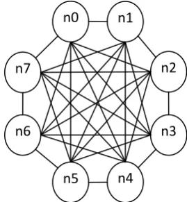
The following Fig. 2 shows that, discrete selection of nodes by grouping four nodes as a group. i.e. nodes n0 to n4 as one group and nodes n5 to n8 as one group.
Analysis time τANL(D) required for identifying fault in discrete RTPs is obtained by referring (7) and (12) as follows
Fig 2: Illustration of two discrete RTPs
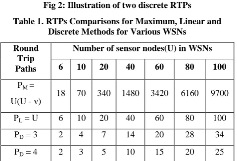
Table 1. RTPs Comparisons for Maximum, Linear and Discrete Methods for Various WSNs
Round Trip Paths
Number of sensor nodes(U) in WSNs
6 10 20 40 60 80 100
PM =
U(U - v) 18 70 340 1480 3420 6160 9700 PL = U 6 10 20 40 60 80 100
PD = 3 2 4 7 14 20 28 34
PD = 4 2 3 5 10 15 20 25
The number of sensor nodes used in RTP are minimum four sensor nodes only, i.e. v=4. Then the equation (15) can be written in terms of U and v as
τANL(D) = (⌊U /4⌋ + C) ∗ 4τ (16) In this type of discrete selection of RTPs will save the analysis time to a large extend. Discrete RTPs obtained using equation (5) in WSNs with different numbers of sensor node U are mentioned in the Table 1. Then the two discrete RTPs selected for wireless sensor network of Fig.1 are illustrated in Fig. 2.
2.3.3
Comparison of RTPs
The numbers of RTPs computed for WSNs with different values of U in Maximum, Linear, Discrete selection with 3 sensor nodes and Discrete selection with 4 sensor nodes cases are used to detect faulty nodes are listed in Table 1. Here in this method finding faulty sensor node, the RTPs are formed by using v = 4.
Table 2. Round Trip Time Analysis of Discrete RTPs with Variable Numbers of Sensor Nodes from 3 to 5 for WSNs
with 50 Sensor Nodes
U v Q=⌊𝑼 /𝒗⌋ R C L = v-1
PT =
Q+C+L
TANL=
PT * 4T
50 3 16 2 1 2 19 76T
50 4 12 2 1 3 16 64T
50 5 10 0 0 4 14 56T
Here for finding faulty sensor node, different techniques are used, these are Maximum selection, Linear selection and Discrete selection. If we are used maximum selection this is a vast process to find faulty sensor node because of many RTPs are created. So it is not best technique for identifying fault sensor node, if we are used linear selection technique, in this type of selection the RTPs are equal to number of sensor nodes. So it is also time taken process for identifying faulty sensor node. Finally if we are used discrete selection this is a best technique for finding faulty sensor node because of reducing RTPs so if we are easily find faulty node. This is a good optimized technique for comparing maximum and linear cases.
The selection of RTPs in discrete selection, finding the faulty sensor node is speed up and avoid complexity process. Referring Table II, the numbers of discrete RTPs required only 31% are used compared on the linear and maximum selection. Hence analysis time of RTPs 69% is not necessary for finding faulty node. So discrete selection is the best and efficiency technique for finding faulty node.
2.4
Generalized RTD Time Model
The quick detection of fault node by using discrete RTPs technique. If the fault node present at first RTPs then we identified and remove from network, Otherwise the fault node present at second or third levels of RTPS then we identified that fault node. Hence total numbers of RTPs used to detect fault are given by
PT = PD + L (17)
Where PT is the total number of RTPs and L is the number of sensor nodes excluding source node of RTPs i.e. L= (v –1). The equation (17) an be written in terms of U and v by referring (12) and (13) as
PT = ⌊U /v⌋ + C + (v - 1) (18)
The analysis time of this proposed method depends upon the RTD times of the RTPs. Then to find the fault sensor node, create a grouping of „v‟ sensor nodes. The formula to find RTD time as
τANL (G) = { ⌊U /v⌋ + C + (v − 1)} ∗ vτ (19)
3.
SOFTWARE ANALYSIS
In this WSNs sensor nodes are formed in circular topology are implemented by using the open source software NS2. In this proposed method round trip paths present between adjacent sensor nodes. In this WSNs adjacent four sensor nodes are form a group. The faulty sensor node is detecting based on compare the adjacent RTPs between sensor nodes.
3.1
Implementation of RTT Protocol in
NS2
In these WSNs the RTP is formed between the four consecutive sensor nodes in the circular topology. If the packet is send from source node to destination node through the intermediate nodes on specify round trip path. The circular topology of WSNs with eight sensor nodes (U = 8) implemented and simulation in NS2 is shown in Fig. 3.
n0
n7
n6
n4
n5
n1
n2
n3
RTP_1
[image:3.595.48.288.251.414.2]Fig 3: WSNs with eight sensor nodes simulated in NS2
3.2
RTD Time Estimation
The RTD Time is detected between the sensor nodes in WSNs. It is essential by considering initially all sensor nodes in WSNs. Here the sensor nodes as 0, 1, 2, 3, 4, 5, 6 and 7 are simulating by with RTD protocol using.
3.3
Detection of Faulty Sensor Node using
RTPs
The sensor node failure may occur in WSN due to battery related problem, uncontrolled environment, in communication device. Failure detection is essential because failed or malfunctioning sensor node may produce incorrect analysis or detection of parameter. Failed sensor node may decrease the quality of service (QOS) of the entire WSN. Manually checking of such failed sensor node in WSN is troublesome. To accomplish the good quality of WSN through efficiency, reliability and accuracy, detection of sensor node failure or malfunctioning is essential. Failed (dead) sensor node detection is done by declaring the particular node as dead. Similarly malfunctioning behaviour is detected by adding certain delay in the RTPs of particular sensor node. Here we are concentrating on finding the faulty or malfunctioning node in the WSN.
Round Trip Path is the time required to send the data from source node to destination node and get the acknowledgement from destination to source through the specified path. The Round Trip Delay Time can be measured by comparing the present RTT with the actual RTT, if the present RTT is greater than or less than the actual RTT, then we can say delay was occur. After specifying delay was occur in the RTP then this system can assume Faulty and malfunctioning Sensor Node can be occur in the network. To find the Faulty and malfunctioning Sensor Node, this system uses discrete path selection technique to find the Faulty and malfunctioning Sensor Node. In this technique grouping four sensor nodes as a group and then we can find the Faulty and malfunctioning Sensor Node by comparing the RTT.
[image:4.595.317.543.72.213.2]The following Fig. 4 shows the detection of Faulty and malfunctioning Sensor Node, which is black colour with hexagon shape.
Fig 4: Faulty node detecting in WSNs
4.
RESULT ANALYSIS
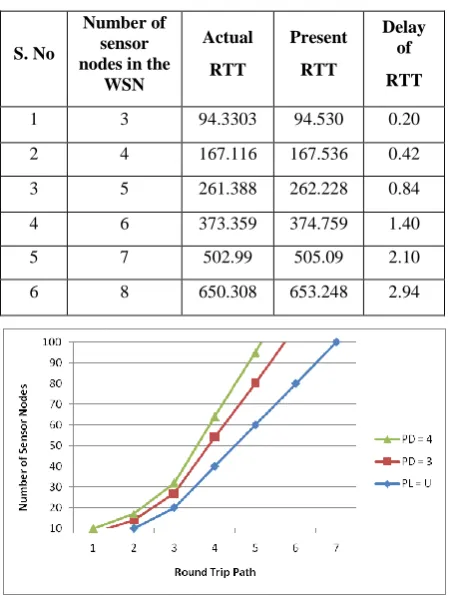
In this method description to detect the faulty node is successfully implemented and tested. In WSNs large number of sensor nodes like 10, 20, 30 and 100 are implemented and tested in NS2 tool. In the above example, Fig. 4 is detect faulty senor node and to prove the efficiency of the proposed method. As various time delays are simulated with this proposed method are listed below the Table 3.
Table 3. Delay Time with Number of Sensor Nodes
S. No
Number of sensor nodes in the
WSN
Actual
RTT
Present
RTT
Delay of
RTT
1 3 94.3303 94.530 0.20
2 4 167.116 167.536 0.42
3 5 261.388 262.228 0.84
4 6 373.359 374.759 1.40
5 7 502.99 505.09 2.10
6 8 650.308 653.248 2.94
Fig 5: Round Trip Path Vs Number of Sensor Nodes
The above figure 5 shows the comparison between the proposed system and existing system in terms of Round Trip Path. PD = 3 refers the existing system uses the 3 sensor nodes
in the Round Trip Path, PD = 4 refers the proposed system
[image:4.595.317.543.339.640.2] [image:4.595.316.542.342.638.2]5.
CONCLUSION
In the proposed method faulty sensor node is detected by discrete path selection technique by compare the actual RTT with present RTT. This method is simulated in NS2 on WSNs with eight sensor nodes designed using circular topology. The Round Trip Delay time comparison for discrete Round Trip Paths is sufficient to detect the faulty sensor node. Efficiency of proposed method is proved in case of discrete RTPs of Round Trip Time with four sensor nodes.
6.
REFERENCES
[1] Ravindra Navanth Duche and Nisha P. Sarwade, “Sensor Node Failure Detection Based on Round Trip Delay and Paths in WSNs” IEEE SENSORS JOURNAL, VOL. 14, NO. 2, February 2014, pp. 455 – 464.
[2] K. Sha, J. Gehlot, and R. Greve, “Multipath routing techniques in wireless sensor networks: A survey,” Wireless Personal Commun., vol. 70, no. 2, pp. 807–829, 2013.
[3] M. Asim, H. Mokhtar, and M. Merabti, “A fault management architecture for wireless sensor network,” in Proc. IWCMC, Aug. 2008, pp. 1–7.
[4] M. Lee and Y. Choi "Fault detection of wireless sensornetworks", Comput. Commun., vol. 31, pp.3469 -3475 2008.
[5] M. Younis and K. Akkaya, “Strategies and techniques for node placement in wireless sensor networks: A survey,” Ad Hoc Netw., vol. 6, no. 4, pp. 621–655, 2008. [6] R. N. Duche and N. P. Sarwade "Sensor node failure or malfunctioningdetection in wireless sensor network", ACEEE Int. J. Commun., vol. 3, no. 1, pp.57 -61 2012. [7] I. Chen, A. P. Speer, and M. Eltoweissy, “Adaptive fault
tolerant QoS control algorithms for maximizing system lifetime of query-based wireless sensor networks,” IEEE Trans. Dependable Secure Comput., vol. 8, no. 2, pp. 1– 35, Mar./Apr. 2011.
[8] T. W. Pirinen , J. Yli-Hietanen , P. Pertil and A. Visa "Detection and compensation of sensormalfunction in time delay based direction of arrival estimation", IEEE CircuitsSyst., vol. 4, no. 1, pp.872 -875 2004.
[9] P. Jiang, “A new method for node fault detection in wireless sensor networks,” Sensors, vol. 9, no. 2, pp. 1282–1294, 2009.
[10]W. Y. Poe and J. B. Schmitt, “Node deployment in large wireless sensor networks: Coverage, energy consumption, and worst-case delay,” in Proc. ACM, AINTEC, Nov. 2009, pp. 1–8.
[11]A. Mojoodi, M. Mehrani, F. Forootan, and R. Farshidi, “Redundancy effect on fault tolerance in wireless sensor networks,” Global J. Comput. Sci. Technol., vol. 11, no. 6, pp. 35-40, Apr. 2011.
[12]T. W. Pirinen, J. Yli-Hietanen, P. Pertil, and A. Visa, “Detection and compensation of sensor malfunction in time delay based direction of arrival estimation,” IEEE Circuits Syst., vol. 4, no. 1, pp. 872–875, May 2004.
7.
AUTHOR’S PROFILE
Aswini Kavarthapu received her B.Tech degree in Information Technology from QIS Institute of Technology, Ongole. Now she is pursuing M.Tech in Computer Science and Engineering in QIS College of Engineering and Technology, Ongole.