1269
ANTENNA EFFECTS ON PHASED ARRAY MIMO RADAR
FOR TARGET TRACKING
1SAMIRAN PRAMANIK, 1NIRMALENDU BIKAS SINHAAND 2CHADAN KUMAR SARKAR
1College of Engineering & Management, Kolaghat, K.T.P.P Township,
Purba Medinipur, 721171, W.B, India.
2Jadavpur University, Kolkata 700032, W.B, India
E-mail: [email protected];
ABSTRACT
Multiple-input multiple-output (MIMO) radar can achieve improved localization performance by employing a coherent processing approach with proper antenna positioning. Coherent processing, however, entails the challenge of ensuring phase coherence of the carrier signals from different distributed radar elements. In recent years, studies have shown how the performances of conventional phased-array radar can be improved by using the same approach. In this work, we aim to address such a challenge by providing a systematic treatment of the phase synchronization problem in coherent MIMO radar systems. We propose and study in coherent MIMO radar and phase array radar with coherent beam for the effectiveness of the above problems. The results show that at high and low SNR values phase array radar with coherent beam provides great improvements of target detection performance over coherent MIMO radar. Simulation results are presented to validate our theoretical analysis.
Keywords: MIMO, Phased array, Coherent, Radar, SNR.
1. INTRODUCTION:
Phased array system has been proposed in the 1950’s and is widely used in communication and radar applications. For communication applications, phased array systems have been employed on either the transmitter or receiver side, or both. Phased array antennas are finding their way more frequently into radar systems [1], [2]. These types of antennas are constructed by assembling radiating elements in a geometrical configuration which are shortly referred as an array. In most cases, the elements of the array are identical and they are placed in a regularly arranged planar grid. The total field of the array is determined as the superposition of the fields radiated by the individual elements. To provide for directive patterns, it is necessary to have the fields from the elements of the array interfere constructively (add) in the desired directions, and interfere destructively (cancel each other) in the remaining space. Further, by controlling the progressive phase difference between the elements, the maximum radiation can be steered into any desired direction to form a scanning.
In the receiver side of phased array systems, strong interferes from different directions can be placed in the nulls of a radiation pattern to nullify interfere
with the desired signals. Another fundamental merit is the improvement of the effective signal-to-noise ratio (SNR) at the output of the receiver by 10log (N) (dB) because the time-delayed signals from the antenna array add coherently while the noise generated by each receiver chain for the antenna elements adds incoherently, hence increasing a channel capacity. For the transmitter side, higher special power efficiency for the phased array systems creates less interference to nearby communication system. To compensate for the time delay between the antenna elements, a phase shifter can be used instead of a variable time delay element for narrow-band applications. The spacing between the antennas is usually chosen to λ�2 be close to for high antenna directivity and no grating lobes. Some of the advantages of phased array systems are given below:
1. Agile and fast beam steering can be achieved because electronically steered beam allows the switching to be completed in a very short time. 2. It has the ability to track multiple targets; because the phased array is able to generate multiple independent beams at the same time to track different targets.
ISSN: 1992-8645 www.jatit.org E-ISSN: 1817-3195
1270 4. It can be used for wideband applications. This can be achieved by adjusting the values of the phase shifters at different frequencies.
In this paper, we focus on the application of the target detection performance [6] of Phased array radar over conventional MIMO radar [7]-[9]. Consider two radar scenarios: a phased array, where the same waveform is transmitted from each antenna; and orthogonal multiple-input–multiple-output (MIMO) radar [5], whereby independent waveforms are transmitted from each antenna. A major benefit of phased array radar is the increment of signal power incident on the target due to beam forming gain; whereas the coherent MIMO radar [3], [4] cannot beam form on transmit resulting in a comparative reduction in SNR. Scaled versions of a single waveform are transmitted by phased-array radar antennas. By adjusting the phase at each antenna results in a concentrated narrow beam of energy onto a scene of interest. The similarities and differences of these radar systems are explored. Detection performances of MIMO radars and phased array radar are compared through numerical simulations by providing the detectors.
2. Performance analysis:
2.1 Phased Array Radar
Phased array radar uses antenna arrays for transmitting and receiving signals. These arrays may be linear or planar. In both the linear and planar arrays the separation between the elements is usually uniform. These arrays may be co-located and even transmit and receive functions can be performed by the same array. The two arrays may also be widely separated allowing the radar system to operate in bistatic mode.
2.1.1 System Model
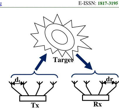
[image:2.612.320.523.76.261.2]The model of the multistatic phased array radar system is shown in Fig.1 that has M transmits and N receives elements. Assume that transmit and receive arrays are uniform linear arrays with inter element spacing of dt and dr respectively. Since the inter-element spacing of phased array radar antennas is small, the bistatic RCS seen by every transmit-receive pair in a phased array radar system is assumed to be the same.
Fig. 1. Phased Array Radar Configuration.
If the transmit array performs transmit beamforming in the direction of θ the transmitted signal(𝒙(𝒕)�) can be written in the vector form as
𝒙(𝒕)
� = 𝑎(𝜃)�𝐸𝑡
𝑀 𝑥(𝑡) … … … (1)
Where, �𝐸𝑡⁄ 𝑥(𝑡)𝑀 denote the discrete time baseband signal transmitted by the transmit antenna elements where 𝑥(𝑡) is the input message signal, 𝐸𝑡 is the total average transmitted energy and where 𝑎(𝜃)is the transmitter steering vector.
Then the received signal model becomes
𝒚 = �𝐸𝑀 𝑁𝑀𝛼 + 𝑤 … … … . (2)𝑡
Where, w is a zero mean vector of complex random processes. Note that if α, where α is a zero mean complex normal random variable, is small, the amplitude of the received signal will be small despite this processing gain and detection probability will decrease dramatically.
2.1.2. Probability Detection
The detection problem in phased array radar can be formulated as binary hypothesis testing problem:
𝐻0 : 𝑦 = 𝑤
𝐻1: 𝑦 = �𝐸𝑡𝑀 𝑀𝑁𝛼 + 𝜔 � … … … (3)
Where 𝐻0 indicates absence of signal and 𝐻1 indicates presence of signal.
Assume that α is a zero mean complex normal random variable with a variance of σα2=1.
It is well known that the optimum solution to this hypothesis testing problem under Neyman-Pearson criterion is the Likelihood Ratio Test (LRT) as,
𝑝(𝑦|𝐻1, ơ𝑤2ơ𝛼2)
𝑝(𝑦|𝐻0, ơ𝑤2) ⪌𝐻0
𝐻1𝑇 … … … … (4)
Rx
Tx
dt
dr
1271 In this case the distributions of 𝛼 and 𝑤 are known,
So the likelihood ratio test [4] can be written as,
|𝑦|2⪌
𝐻0
𝐻1𝑇′… … … (5)
When there is no target, the distribution of |𝑦|2exponential [5] and can be written as,
|𝑦|2∼ 𝑒𝑥𝑝 � 1
𝑁ơ𝑤2� … … . . . (6)
The false alarm rate (𝑃𝑓𝑎) can be defined in the term of threshold 𝑇′, as,
= 𝑒𝑥𝑝 �𝑁ơ𝑤−𝑇′2� … … … . (7)
Where, 𝑇′= −𝑁ơ𝑤2𝑙𝑛�𝑃𝑓𝑎�
When target is present, the distribution of |𝑦|2 is again exponential [6] with rate parameter is equal
to 𝐸𝑡𝑀𝑁2+ 𝑀𝑁σ𝑤2 and can be written as,
|𝑦|2∼ 𝑒𝑥𝑝 � 1
𝐸𝑡𝑀𝑁2+ 𝑀𝑁ơ𝑤22�
The probability detection(𝑃𝑑) can be calculated in terms of threshold 𝑇′ as,
= 𝑒𝑥𝑝 �𝐸 −𝑇′
𝑡𝑀𝑁2 + 𝑁ơ𝑤2� ………. (8)
Equivalently probability detection(𝑃𝑑)can be written in terms of 𝑃𝑓𝑎and SNR as,
𝑃𝑑= 𝑒𝑥𝑝 �(𝑆𝑁𝑅)𝑀𝑁 + 1� … … … . (9)𝑙𝑛�𝑝𝑓𝑎�
2.1.3. Results and Observation
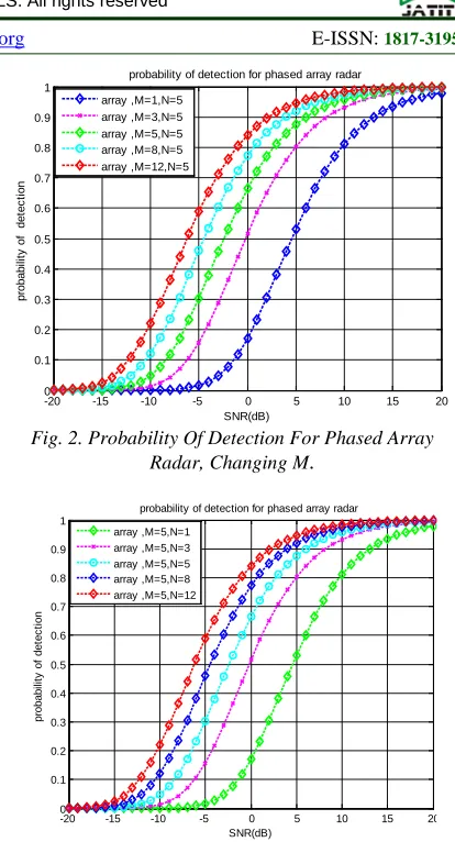
To illustration the probability detection performance of phased array radar, the detector in equation (9) is implemented for which 𝑃𝑓𝑎value is set to 10−2 .The resulting 𝑃𝑑vs SNR curve is represented in Fig. 2. The detection performance of the phased array radar system enhances as the number of transmit antennas increases although the transmitted power is constant. The gain increases as the number of transmit antenna increases although the noise power in the received signal remains constant.
[image:3.612.312.519.64.447.2]If the number of transmit elements is held constant at the value of 5 and the number of receive elements is increased, the 𝑃𝑑vs. SNR curve in Fig. 3 is obtained. We can see from the graph that as number of receiving antennas is increased the probability of detection increases, because the total received energy increases.
Fig. 2. Probability Of Detection For Phased Array
[image:3.612.82.520.69.460.2] [image:3.612.84.308.82.424.2]Radar, Changing M.
Fig. 3. Probability Of Detection For Phased Array Radar, Changing N.
2.2 Coherent MIMO Radar
Coherent MIMO radar uses antenna arrays for transmitting and receiving signals. These arrays may be co-located and even transmit and receive functions can be performed by the same array or the arrays may be separated. The separation between the elements may be uniform or non-uniform. The arrays can be filled or sparse depending on the application type. But the separation is always small compared to the range extent of the target. Whatever the separation between the array elements is, the important point in coherent MIMO radar is that the array elements are close enough so that every element sees the same aspect of the target i.e. the same RCS. As a result, point target assumption is generally used in coherent MIMO radar applications.
2.2.1. Signal model
Consider a coherent MIMO radar system that has transmit and a receive array consisting of M and N elements respectively.
-20 -15 -10 -5 0 5 10 15 20 0
0.1 0.2 0.3 0.4 0.5 0.6 0.7 0.8 0.9 1
SNR(dB)
pr
obabi
lit
y
of
det
ec
ti
on
probability of detection for phased array radar array ,M=1,N=5
array ,M=3,N=5 array ,M=5,N=5 array ,M=8,N=5 array ,M=12,N=5
-20 -15 -10 -5 0 5 10 15 20 0
0.1 0.2 0.3 0.4 0.5 0.6 0.7 0.8 0.9 1
SNR(dB)
pr
obabi
li
ty
of
det
ec
ti
on
probability of detection for phased array radar array ,M=5,N=1
ISSN: 1992-8645 www.jatit.org E-ISSN: 1817-3195
[image:4.612.94.289.81.278.2]1272
Fig.4. Coherent MIMO Radar Configuration.
Then the received signal can be written as
𝑦(𝑡) = �𝐸𝑀 H𝑥𝑡 (𝑡 − 𝜏) + 𝑤(𝑡) … … . (10)
Where, �𝐸𝑡⁄ 𝐻𝑥(𝑡 − 𝜏)𝑀 denote the discrete time baseband signal transmitted by the transmit antenna elements where 𝑥(𝑡 − 𝜏) is the input message signal with delay time, 𝐸𝑡is the total average transmitted energy and 𝑤(𝑡) is the noise vector.
2.2.2. Probability detection
The detection problem here can be formulated as binary hypothesis testing problem as follows:
𝐻0: 𝑦� = 𝑤�
𝐻1: 𝑦� = �𝐸𝑡𝑀 𝛼� + 𝑤�� … … … (11)
Where 𝐻0 indicates absence of signal and 𝐻1 indicates presence of signal.
The probability of false alarm rate, 𝑃𝑓𝑎 can be calculated as,
𝑃𝑓𝑎= 𝑃𝑟𝑜𝑏 �𝑒𝑥𝑝 �𝑀𝑁1ơ
𝑤
2� > 𝑇′�
= 𝑒𝑥𝑝 �𝑀𝑁𝑇′ơ
𝑤
2� ….... (12) Then 𝑃𝑑 can be written in terms of SNR and probability of false alarm rate as,
𝑃𝑑= 𝑒𝑥𝑝 �(𝑆𝑁𝑅)𝑁 + 1� … … . (13)𝑙𝑛�𝑃𝑓𝑎�
So, the probability of detection does not depend on the number of transmit antennas but depends only on number of receive antennas and SNR.
2.2.3. Results
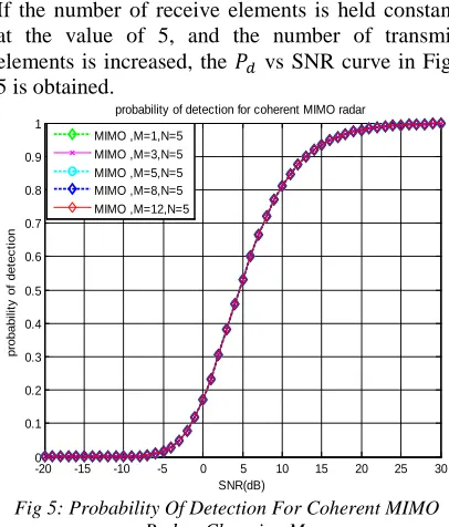
To compare with the detection performance of Coherent MIMO Radar, the detector in (6) is implemented. 𝑃𝑓𝑎value is set to 10−6.
If the number of receive elements is held constant at the value of 5, and the number of transmit elements is increased, the 𝑃𝑑 vs SNR curve in Fig. 5 is obtained.
Fig 5: Probability Of Detection For Coherent MIMO Radar, Changing M.
The graphics in Fig. 5 show that the detection performance does not change with increasing M. This is because the transmitted power is normalized and it does not change with the number of transmit elements, and also because the noise power and the signal power in the received signal after coherent summation increase at the same rate.
If the number of transmit elements is held constant at the value of 5 and the number of receive elements is increased, the 𝑃𝑑vs SNR curve in Fig. 6 is obtained. We can see from the graph that as number of receiving antennas is increased the probability of detection increases, because the total received energy increases.
The detection performance of phased array radar system is better than the coherent MIMO radar system in every case. This is an expected result since total noise in the received signal is equal to𝑁𝜎𝑤2 in the phased array radar case whereas it is higher and equal to 𝑀𝑁𝜎𝑤2 in coherent MIMO radar case.
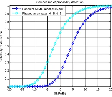
To see the performance difference clearly, the receiver operating curves of phased array radar and coherent MIMO radar is given in Fig. 7 and as well as Fig. 8. This figure is obtained using the analytical expressions given in Equations (9) and (13).
-20 -15 -10 -5 0 5 10 15 20 25 30 0
0.1 0.2 0.3 0.4 0.5 0.6 0.7 0.8 0.9 1
SNR(dB)
pr
obabi
li
ty
of
det
ec
ti
on
probability of detection for coherent MIMO radar MIMO ,M=1,N=5
MIMO ,M=3,N=5 MIMO ,M=5,N=5 MIMO ,M=8,N=5 MIMO ,M=12,N=5 Target
TX
[image:4.612.315.518.95.333.2]1273
Fig. 6. Probability Of Detection For Coherent MIMO Radar, Changing N.
[image:5.612.99.293.442.610.2]Fig. 7: ROC- Coherent Vs. Phased Array MIMO.
Fig. 8: Comparison Of Probability Detection For Phased Array Radar Vs. Coherent MIMO Radar.
In the Fig. 7, the red lines belong to coherent MIMO radar and the blue lines belong to phased array radar. Again it can be seen from the Fig. 8 that phased array radar outperforms coherent MIMO radar in every case and also that the as the SNR increases the performance of both the radar improves.
3. CONCLUSION
In this paper, the analytical description of the coherent MIMO approach to phased-array radars with coherent beam has been provided. With respect to the retrieved representation, a design procedure for phase array MIMO with coherent beam structures was introduced. Practical realization of the coherent processing in MIMO radar systems requires the development of implementable techniques to ensure a common notion of phase among all the distributed radar elements. In this work, we proposed and studied effective approaches to achieve phase synchronization in coherent MIMO radar systems by using phase array radar with coherent beam. We discussed some issues that may arise in practice when implementing these algorithms, and also provided simulation results that are focused on the Neyman-Pearson sense based algorithm. These simulation results indicate a good match with our theoretical analysis.
REFERENCES
[1] M. I. Skolnik, Introduction to Radar Systems, 3rd ed. New York: Mc-Graw-Hill, 2001. [2] S. Haykin, J. Litva, and T. J. Shepherd, Radar
Array Processing. New York: Springer-Verlag, 1993.
[3] J. Li and P. Stoica, “MIMO radar with colocated antennas,” IEEE Signal Processing Magaz., vol. 24, no. 5, pp. 106–114, Sept. 2007. [4] R. Gerchberg and W. Saxton, “A practical
algorithm for the determinationof phase from image and diffraction plane pictures,” Optik, vol.35, no. 2, pp. 237–248, 1972.
[5] E. Fishler, A. Haimovich, R. Blum, D. Chizhik, L. Cimini, and R.Valenzuela, “MIMO radar: An idea whose time has come,” in Proc.IEEE Radar Conf., Honolulu, HI, Apr. 2004, vol. 2, pp. 71– 78.
[6] E. Fishler, A. Haimovich, R. Blum, L. Cimini, D. Chizhik, and R.Valenzuela, “Spatial diversity in radars—Models and detection performance,”IEEE Trans. Signal Process., vol. 54, pp. 823–838, Mar. 2006.
[7] J. Li and P. Stoica, “MIMO radar with colocated antennas,” IEEESignal Process. Mag., vol. 24, pp. 106–114, Sep. 2007.
[8] Yang Yang and Rick S. Blum,” Phase Synchronization for Coherent MIMO Radar: Algorithms and Their Analysis” IEEE
TRANSACTIONS ONSIGNAL
PROCESSING, VOL. 59, NO. 11, pp. 5538-5557, NOVEMBER 2011.
-20 -15 -10 -5 0 5 10 15 20 0 0.1 0.2 0.3 0.4 0.5 0.6 0.7 0.8 0.9 1 SNR(dB) pr obabi li ty of det ec ti on
probability of detection for coherent MIMO radar MIMO ,M=5,N=1
MIMO ,M=5,N=3 MIMO ,M=5,N=5 MIMO ,M=5,N=8 MIMO ,M=5,N=12
100-15 10-10 10-5 100
0.2 0.4 0.6 0.8 1
False Alarm Rate
P ro b a b ility o f D e te c tio n
ROC - Coherent Vs Phased Array MIMO
snr=-5 snr=-5 snr=0 snr=0 snr=5 snr=5 snr=10 snr=10 snr=15 snr=15
-20 -15 -10 -5 0 5 10 15 20 0 0.1 0.2 0.3 0.4 0.5 0.6 0.7 0.8 0.9 1 SNR(dB) pr obabi li ty of det ec ti on
ISSN: 1992-8645 www.jatit.org E-ISSN: 1817-3195
1274 [9] Francesco Belfiori, Wim van Rossum, and Peter
![Assessment of Physiological Health Status in Relations to Different Anthropometric and Cardio respiratory Measures of Head Supported Load Carrying Male Porters of Sikkim, India [Article Retracted]](data:image/gif;base64,R0lGODlhAQABAIAAAP///wAAACH5BAEAAAAALAAAAAABAAEAAAICRAEAOw==)