ii
DESIGN AND SIMULATION STUDY OF OBSTACLE BASED PASSIVE MICROMIXER
MAIZUL HAFFIN BIN ZULKARNAIN
A project report submitted in partial fulfillment of the Requirement for the award of the
Degree of Master of Electrical engineering
Faculty of Electrical and Electronic Engineering Universiti Tun Hussein Onn Malaysia
ABSTRACT
vii
ABSTRAK
Micromixer boleh terbahagi kepada dua kategori iaitu micromixer aktif dan
micromixer pasif. Oleh kerana teknologi fabrikasi yang mudah dan mudah
disesuaikan dalam sistem microfluidic yang kompleks , halangan berasaskan micromixers pasif akan menjadi tumpuan projek ini. Oleh kerana aliran lamina (
TABLE OF CONTENT
CHAPTER TITLE PAGE
TITLE ii
CONFESSION iii
ACKNOWLEDGEMENT v
ABSTRACT vi
ABSTRAK vii
TABLE OF CONTENTS viii
LIST OF TABLE xii
LIST OF FIGURE xiv
LIST OF SYMBOL AND ABBREVIATION xix
CHAPTER 1 INTRODUCTION 1
1.1 BACKGROUND STUDY 2
1.2 PROBLEM STATEMENT 4
1.3 SIGNIFICANT STUDY 5
1.4 OBJECTIVE 5
1.5 SCOPE 6
ix
CHAPTER 2 LITERATURE REVIEW 8
2.1 LITERATURE REVIEW 9
2.2 HYDRODYNAMIC FOCUSING 10
2.3 INJECTION 12
2.4 GEOMETRY EFFECT 15
2.5 DROPLET 21
2.6 SUMMARY 25
CHAPTER 3 METHODOLOGY 26
3.1 FLOW CHART 27
3.2 DESIGN CONSIDERATION 28
3.3 MICROFLUIDIC 29
3.4 TRANSPORT PHENOMENA 33
3.5 GEOMETRY DESIGN 34
3.6 SIMULATION AND ANALYSIS 37
CHAPTER 4 RESULTS AND DISCUSSION 40
4.1 SIMULATION SETUP 40
4.2 DESIGN OF MICROMIXER 42
4.3 QUALITATIVE ANALYSIS FOR MICROMIXER
46
4.3.1 BASIC Y MICROMIXER 46
4.3.2 OBSTACLE ORIENTATION EFFECT IN MICROMIXER
47
4.3.3 IMPACT NUMBERS OBSTACLE IN MICROMIXER
52
4.4 QUANTITATIVE ANALYSIS FOR MICROMIXER
54
4.5.1 QUALITATIVE ANALYSIS 69 4.5.2 STANDARD DEVIATION FOR
VISCOSITY
70
4.5.3 MIXING EFFICIENCY 72
CHAPTER 5 CONCLUSION 76
5.1 CONCLUSION 76
5.2 RECOMMENDATION 78
REFERENCES 79
xi
LIST OF TABLE
TABLE PAGE
2.1
Summary of the main features of various means for micromixing and their overall rank for use in microfluidic devices as a mixer.
25
3.1 Some mass diffusion coefficients at 250C 29
3.2 Physical properties of the fluids 30
3.3 Calculation to find V for blood 31
3.4 Calculation to find V for glycerin 32
3.5 Result for run with different Re value 32
4.1 The viscosity’s standard deviation of basic Y shape micromixer
55
4.2 The viscosity’s standard deviation for Y shape with obstacle SAR technique micromixer
56
4.3 The viscosity’s standard deviation for Y shape with internal rib micromixer
57
4.4 The viscosity’s standard deviation of Y shape with zigzag obstacle micromixer
58
4.5 The viscosity’s standard deviation for Y shape with mirrored zigzag obstacle micromixer
59
4.6 The viscosity’s standard deviation of Y shape with vertical obstacle meandering design micromixer
60
4.7 The viscosity’s standard deviation for Y shape with obstacle meandering design micromixer
4.8 The mixing efficiency of basic Y shape micromixer 62 4.9 The mixing efficiency of Y shape with obstacle SAR
technique micromixer
63
4.10 The mixing efficiency of Y shape with internal rib micromixer
64
4.11 The mixing efficiency of Y shape with zigzag obstacle micromixer
65
4.12 The mixing efficiency for Y shape with mirrored zigzag obstacle micromixer
66
4.13 The mixing efficiency of Y shape with vertical obstacle meandering design.
67
4.14 The mixing efficiency of Y shape with obstacle meandering design micromixer
68
xiii
LIST OF FIGURE
FIGURE PAGE
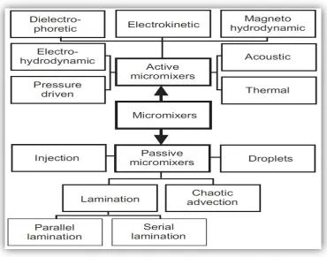
1.1 Overview of different micromixer types 3
2.1 (a) Experimental and (b) numerical visualizations of fluid mixing in hydrodynamic focusing channels
10
2.2 A multilaminated/elongational flow micromixer 11 2.3 A schematic illustrating the structure of the chessboard
mixer
11
2.4 An alternate-injection mixer composed of an inlet cross channel and a larger chamber
13
2.5 Three types of inlet channels; (a) single “T”, (b) double “T” and (c) double cross channel
14
2.6
Distribution of species concentration in wavy-wall channels by (a) continuous injection, (b) pulsed injection with a certain period and (c) pulsed injection with the period double that for (b)
14
2.7 A serpentine laminating micromixer composed of a series of F-shaped channel units
16
2.8 Three kinds of two-layer microchannels 17
2.9
(a, b) Sketch of the two kinds of channel mixer with a single-layer structure and (c) the cross-sectional view of the plane cut by a dotted line in (b)
2.10 Development of the striation pattern inside the channel (from a to f) showing chaotic advection
17
2.11 Top view of the channel designs with different fractal patterning of bottom grooves and SHM
18
2.12 Schematic of the two channel designs of CGM (connected-groove micromixer) with not only bottom but also side grooves: (a) CGM-1 design; (b) CGM-2 design
18
2.13 Enlarged view of the SAR unit (left) composing the 8-unit mixer
19
2.14
(a) Perspective view of SAR mixer with steps and partitioning blocks on the bottom wall and (b) schematic illustration of mixing principle
20
2.15
(a) comparison of the mixing patterns from numerical (left) and experimental (right) results for each section of the channel (denoted as (a), (b), (c) and (d) shown on the top) of a cross-baffle mixer
20
2.16 A meandering channel with bumps on the outer side for use in mixing three kinds of liquids
22
2.17
Coalescing of two droplets in a (a) side-by-side and (b) longitudinal arrangement. Mixing performance is plotted in (c): ■, mixing of dye and water in a side-by-side coalescence configuration; ●, mixing of dye and water in a longitudinal coalescence configuration; ○, bleaching reaction in a longitudinal coalescence configuration. Here a low level of χ means a better mixing effect
23
2.18 A microchannel mixer with an air-inlet port to produce isolated droplets for better mixing
xv
3.1 Flowchart for project planning 27
3.2
Concentration distribution in a parallel lamination micromixer: (a) the two-dimensional model; and (b) the dimensionless two-dimensional model
28
3.3 Value for both liquids in Autodesk software 30
3.4 The basic Y shape 35
3.5 The Y shape with obstacle as propose in PS1 35
3.6 The Y shape with internal rib 35
3.7 The Y shape with obstacle design 2 35
3.8 The Y shape with obstacle design 3 36
3.9 The Y shape with obstacle design 4 36
3.10 The Y shape with obstacle design 5 36
4.1 The summary had shown that the flow is laminar and steady
41
4.2 The summary had shown that the value for Re is same with calculation
41
4.3 The basic Y shape 42
4.4 The Y shape with obstacle SAR technique 43
4.5 The Y shape with internal rib 43
4.6 The Y shape with zigzag obstacle 44
4.7 The Y shape with mirrored zigzag obstacle 44 4.8 The Y shape with vertical obstacle meandering design 45 4.9 The Y shape with obstacle meandering design 45
4.10
The color intensity of the fluids diffusion. As mentioned earlier, Y-mixer depends entirely on molecular diffusion. So, a very long channel is needed for the two fluids to be mixed
46
4.11 Fluids flow based on viscosity for basic Y micromixer 47 4.12 The color intensity for Y shape with obstacle SAR
technique micromixer
4.13 Fluids flow based on viscosity for Y shape with obstacle SAR technique micromixer
48
4.14 The color intensity for Y shape with internal rib 49 4.15 Fluids flow based on viscosity for Y shape with internal
rib
49
4.16 The color intensity for Y shape with zigzag obstacle micromixer
50
4.17 Fluids flow based on viscosity for Y shape with zigzag obstacle micromixer
50
4.18 The color intensity for Y shape with mirrored zigzag obstacle micromixer
51
4.19 Fluids flow based on viscosity for Y shape with mirrored zigzag obstacle micromixer
51
4.20 The color intensity for the Y shape with vertical obstacle meandering design micromixer
52
4.21 Fluids flow based on viscosity for the Y shape with vertical obstacle meandering design
52
4.22 The color intensity for the Y shape with obstacle meandering design micromixer
53
4.23 Fluids flow based on viscosity for the Y shape with obstacle meandering design micromixer
53
4.24 Viscosity’s standard deviation vs. steps for basic Y micromixer
55
4.25 Viscosity’s standard deviation vs. steps for the Y shape with obstacle SAR technique micromixer
56
4.26 Viscosity’s standard deviation vs. steps for Y shape with internal rib
57
4.27 Viscosity’s standard deviation for Y shape with zigzag obstacle micromixer
xvii
4.28 Viscosity’s standard deviation for Y shape with mirrored zigzag obstacle micromixer
59
4.29 Viscosity’s standard deviation for Y shape with vertical obstacle meandering design micromixer
60
4.30 Viscosity’s standard deviation for Y shape with obstacle meandering design micromixer
61
4.31 Mixing efficiency vs. steps for basic Y micromixer 62 4.32 Mixing efficiency vs. steps for Y shape with obstacle
SAR technique micromixer
63
4.33 Mixing efficiency vs. steps for Y shape with internal rib micromixer
64
4.34 Mixing efficiency vs. steps for Y shape with zigzag obstacle micromixer
65
4.35 Mixing efficiency vs. steps for Y shape with mirrored zigzag obstacle micromixer
66
4.36 Mixing efficiency vs. steps for Y shape with vertical obstacle meandering design micromixer
67
4.37 Mixing efficiency vs. steps for Y shape with vertical obstacle meandering design micromixer
68
4.38
2D analysis (a) basic Y micromixer (b) Y shape with obstacle as propose in PS 1 (c) Y shape with internal rib (d) Y shape with obstacle design 2 (e) Y shape with obstacle design 3 (f) Y shape with obstacle design 4 (g) Y shape with obstacle design 5
69
4.39 Comparison for standard deviation for each design 71
4.40 The comparison of mixing efficiency 72
4.41 The mixing efficiency at the end of channel for each design
LIST OF SYMBOL AND ABBREVIATION
Symbols /
Abbreviation
LOC Lab On Chip
CFD Computational Fluid Dynamics PDMS Polydimethylsiloxane
SHM Staggered Herringbone Mixer CGM Connected-Groove Micromixer
SAR Split And Recombined ρ Fluid density
v Fluid velocity D Vessel diameter µ Fluid viscosity
CHAPTER 1
INTRODUCTION
1. INTRODUCTION
In biomedical and chemical analysis, a sample solution is often to be tested with a reagent. The two solutions should be well mixed to make the reaction possible. While in microscale, mixing is achieved with turbulence, mixing in microscale relies mainly on diffusion due to the laminar behavior at low Reynolds numbers.
Micromixers are categorized as passive mixers and active mixers. Passive mixers do not have moving parts. Micropumps or microvalves used to deliver fluids to the mixing area are not considered part of the mixer. In active mixers, moving parts are involved. Moving parts are used to manipulate or control the pressure gradients in the mixing area. Because of the nature of the mixing phenomena, the two mixer types are also called static and dynamic mixers. Because of their simple implementation, passive mixers are a favorable solution for microfluidic systems.
Conventionally, turbulent flows and mechanical agitation make rapid mixing possible by segregating the fluid in small domains, which increase the contact surface and decrease the mixing path. Since the Reynolds numbers in microfluidic devices are on the order of 1 or less, far below the critical Reynolds number, turbulence is not achievable in microscale. All micromixers work in laminar regime and rely entirely on diffusion. General design requirements for micromixers are fast mixing time, small device area, and integration ability in a more complex system.
3
[image:17.595.135.506.214.505.2]of disturbance fields, the design of active micromixers is often complicated and requires a complex fabrication process. The integration of active mixers in a microfluidic system is therefore both challenging and expensive. The major advantage of passive micromixers is the lack of actuators. The simple passive structures are robust, stable in operation, and easy to be integrated. Figure 1 illustrates the systematic overview of different micromixer types.
Generally, active micromixers have higher mixer efficiency. However, the requirement to integrate peripheral devices such as the actuators for the external power source into the microdevice, and the complex and expensive fabrication process, limit the implementation of such devices in practical applications. In addition, in active mixing mechanisms such as ultrasonic waves, high temperature gradients can damage biological fluids. Therefore, active mixers are not a popular choice when applying microfluidics to chemical and biological applications.
Passive mixing devices rely entirely on fluid pumping energy and use special channel designs to restructure the flow in a way that reduces the diffusion length and maximizes the contact surface area. Passive mixers were the first microfluidic device reported, often entail less expense and more convenient fabrication than active micromixers, and can be easily integrated into more complex LOC devices. The reduction in mixing time is generally achieved by splitting the fluid stream using serial or parallel lamination], hydrodynamically focusing mixing streams, introducing bubbles of gas (slug) or liquid (droplet) into the flow, or enhancing chaotic advection using ribs and grooves designed on the channel walls.
There are many different ways to provide mixing in macroscale such as molecular diffusion, eddy diffusion, advection, and Taylor dispersion. Eddy diffusion is the transport of large groups of species and requires a turbulent flow. Because of the dominant viscous effect at the microscale, turbulence is not possible in micromixers. Mixing based on eddy diffusion is therefore not relevant for micromixers.
5
A simple Eulerian velocity can lead to a chaotic distribution of the mixed species. A stable and laminar flow can also lead to chaotic advection. Thus, chaotic advection would be ideal for the laminar flow condition in micromixers. Taylor dispersion is advection caused by a velocity gradient. Axial dispersion occurs due to advection and interdiffusion of fluid layers with different velocities. Due to this effect, mixing based on Taylor dispersion can be two or three orders faster than mixing based on pure molecular diffusion.
1.3. SIGNIFICANT STUDY
Due to this project, the new design of micromixer is being study. It helps medical researchers and others to understand the concept and make the comparison which design will get the fastest time for fluids to mix. This design can be applied on LOC and the result can be drawn faster and more efficient. It will help, for example the doctor can give patient suitable treatment based on the result from micromixer test in very short time.
1.4. OBJECTIVE
The following are the objectives of this project:
i. To build a new design of microchannel of passive micromixer using split and recombined technique plus rib technique with single layer structure.
ii. To analyze the fluids mixing performances via color changes, viscosity’s standard deviation and mixing efficiency among the selected micromixers iii. To perform a comparative analysis and to select the optimum design among
There is a lot of ground need to cover for this project and there are so many designs in passive micromixer from the basic shaped, parallel lamination micromixer, sequential lamination micromixer, focusing enhanced mixer, chaotic advection micromixer and droplet micromixer. To make the comparison between those designs, will take a lot of time also energy.
Designing micromixers is a completely new engineering discipline, because existing designs in macroscale cannot simply be scaled down for microscale applications. One of the main challenges related to miniaturization is the dominance of surface effects over volume effects. Actuation concepts based on volume forces working well at the macroscale may have problems at the microscale.
Besides surface phenomena, the laminar flow condition is another challenge for designing micromixers. For many applications, the flow velocity in micromixers cannot be too high. The small size of micromixers leads to an extremely large shear stress in mixing devices, even at relatively slow flow velocities. This shear stress may damage cells and other sensitive bioparticles. Advection allows improved mixing in fluid flows at low Reynolds number. In most passive micromixers based on molecular diffusion, advection is parallel to the main flow direction. Thus, transversal transport of species relies entirely on molecular diffusion. Advection with a three-dimensional orbit can cause secondary transversal transport and significantly improve mixing. The basic design concept for the generation of advection is the modification of the channel shape for stretching, folding, and breaking of the laminar flow.
7
1.6. REPORT OUTLINE
Chapter 1 has presented a briefly introduction of the thesis project mainly about micromixer which consist of passive and active also microfluidic, the problem that we are facing, the objectives of the project and also the scope or the limitation of the project itself.
Chapter 2 will present more deeply into the related topic of microfluidic for passive and active micromixer. This chapter will also explain more about the fundamental of mixing fluid, the Reynold number and the mathematical background of fluid flow.
Chapter 3 will present the methodology used to complete this project. Using only Autodesk inventor and CFD software, is the method used to compare and analyze the result. But before using this software, all the specifications including the details of the design of the chosen passive micromixer will be included in this chapter. The details are: the Reynold number used the length of the channel, the depth of the channel, the details of the fluid used etc.
Chapter 4 is the result and discussion for all the analysis of the seven micromixers for evaluation. The result and analysis are based on viscosity performances, viscosity’s standard deviation and also the mixing efficiency.
CHAPTER 2
LITERATURE REVIEW
2. INTRODUCTION
9
2.1. LITERATURE REVIEW
Over the past two decades, lab-on-a-chip (LOC) technologies have driven considerable progress in the development of microsystems, particularly for chemical, biological, and medical applications. The exponential increase of research in miniaturization and in microfluidic applications highlights the importance of understanding the theory and the mechanisms that govern mixing at the microscale level. This chapter will review the most recent research and developments in mixing processes within microfluidic devices.
Jayaraj et al. [1] presented a review on the analysis and experiments of fluid flow and mixing in microchannels, but their review was based on the literature published mostly before 2005. Very recently, Falk and Commenge [2] addressed use of the method of performance comparison or evaluation of micromixers by using the Villermaux/Dushman reaction. They combined the order-of magnitude analysis and a phenomenological model to derive relation between the mixing time and other parameters such as the Reynolds number. However, no review paper has been found which addresses key features of various types of micro mixers and evaluates them in terms of their mixing performance, versatility of application and difficulty of fabrication, etc. This review paper summarizes the fundamental ideas behind the mixer designs presented in the papers published in 2005 and thereafter, as well as the application range and the fabrication difficulty of these.
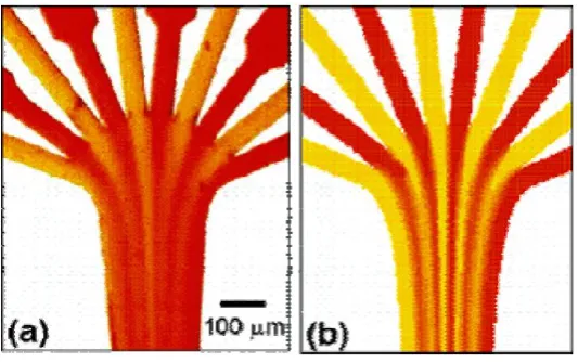
From previous paper, Floyd et al. [3] fabricated a silicon microchannel with 10 inlets for mixing acid and base solutions (Figure 2.1). Their experimental measurement for the mixing performance was compared with computational fluid dynamics (CFD) results with good agreement in terms of the residence time. Nguyen and Huang [4] presented a comparison between the analytical solution and the experimental measurement of the diffusion of samples in a hydrodynamic focusing means.
Figure 2.1: (a) Experimental and (b) numerical visualizations of fluid mixing in hydrodynamic focusing channels (from Floyd et al. [3]).
11
Figure 2.2: A multilaminated/elongational flow micromixer (from Adeosun and Lawal [5, 6]).
Cha et al. [7] proposed a 3D micromixer combining the focusing and split-and-recombination (SAR) functions called the chessboard mixer (Figure 2.3). For the flow rate of 12.7 μL/min, 90% of mixing occurs only within the length of 1.4 mm. Park et al. [8] demonstrated the use of sheath flows from the hydrodynamic focusing as an effective method in controlling the reaction of samples. They fabricated five inlet channels: the center for an analyte solution, the two sides for the solution B and the two diagonals for the solution A. In this way, they could prevent the undesired premixing of solutions before the focusing was completed. Mimicking the geometrical properties of a vascular system, Cieslicki and Piechna [9] designed a branched channel and numerically investigated the mixing performance, particularly focusing on the effect of the number of branches.
[image:25.595.135.501.572.713.2]mixing time. The main problem in the hydrodynamic focusing, however, lies in how to distribute the fluids to the multiple inlet channels. Typically, for the mixing of two samples, each sample is stored in one of the two different reservoirs while multiple channels used for the focusing are usually arranged in a staggered way. Then the fabrication of the inlets must be of a two-layer structure, which adds to the complexity in the overall device design.
2.3. INJECTION
Another popular method for enhancing the mixing performance is to inject samples of different species at the inlet in an alternating way; in view of each sample, the resulting flow is similar to a pulsed flow. Compared with the hydrodynamic focusing case, the alternate injection design does not require complex channel fabrication. MacInnes et al. [10] conducted a numerical and analytical study on the mixing performance for a case in which two different samples are introduced into the channel via a pulsating pressure. Such alternate injection increases the interfacial area, leading to a fast mixing. Goullet et al. [11] studied the effect of the geometry of the inlet channel (i.e., “T” and “Y”, etc.) as well as the phase difference between the two injected samples on the mixing performance of the pulsed-flow mixer. They also introduced ribs in the main channel and demonstrated significant improvement in the degree of mixing.
13
[image:27.595.182.454.135.324.2]mixing in their specific parameter settings is in the range 1–2 Hz. Similar designs have also been proposed by Leong et al. [14] and Sun and Sie [15].
Figure 2.4: An alternate-injection mixer composed of an inlet cross channel and a larger chamber (from Coleman et al. [13]).
Figure 2.5: Three types of inlet channels; (a) single “T”, (b) double “T” and (c) double cross channel (from Fu and Tsai [16]).
Figure 2.6: Distribution of species concentration in wavy-wall channels by (a) continuous injection, (b) pulsed injection with a certain period and (c) pulsed
injection with the period double that for (b) (from Chen and Cho [18]).
[image:28.595.187.447.372.479.2]15
2.4. GEOMETRY EFFECT
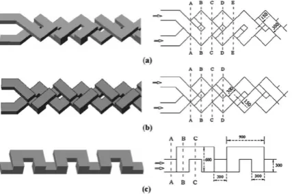
Apparently, the simplest way to enhance mixing in a microchannel is to make the channel geometry complex, e.g., a serpentine structure [19], or with grooves [20] or blocks [21] on the bottom wall. Kim et al. [22] proposed a two-layer microchannel composed of a series of F-shaped channel units (Figure 2.8), which was shown to bring chaotic advection via the stretching-folding mechanism. Xia et al. [23] compared three kinds of two-layer crossing channels in terms of the mixing effect including the basic serpentine mixer proposed by Liu et al. [19].
Their two types of design (Figures 2.8a and 2.8b) revealed much better mixing performance than the basic serpentine structure (Figure 2.8c) at low Reynolds numbers, implying that the basic serpentine microchannel is not suitable for low Reynolds-number flows. Further support for this argument was given by the numerical simulation of Ansari and Kim [24]. The two-layer structures proposed by Kim et al. [22] and Xia et al. [23] are shown to provide chaotic advection, but again the main disadvantage of those structures is that the fabrication of the two layers separately should increase the device price.
Figure 2.7: A serpentine laminating micromixer composed of a series of F-shaped channel units (from Kim et al. [22]).
As a single layer structure, the mixer proposed by Simonnet and Groisman [27] deserves our attention. Their design is composed of a complex but single layer of PDMS (polydimethylsiloxane) attached to a top planar wall (Figure 2.9). Visualization of a dye of very low diffusivity indeed demonstrated chaotic advection inside the channel, as shown in Figure 2.10. The proposed design is shown to provide excellent mixing when two samples are introduced in the upper and lower domains of the channel section, but it is implied that no stirring occurs when they are introduced in the left and right domains, the latter corresponding to the most common situations. To shorten the mixing length, Camesasca et al. [28] proposed fractal patterning of grooves on the bottom of the channel (Figure 2.11).
17
[image:31.595.230.408.283.457.2]Figure 2.8: Three kinds of two-layer microchannels (from Xia et al. [23]).
Figure 2.9: (a, b) Sketch of the two kinds of channel mixer with a single-layer structure and (c) the cross-sectional view of the plane cut by a dotted line in (b)
(from Simonnet and Groisman [27]).
[image:31.595.223.415.565.703.2]Figure 2.11: Top view of the channel designs with different fractal patterning of bottom grooves and SHM (modified staggered herringbone mixer) (from Camesasca
et al. [28]).
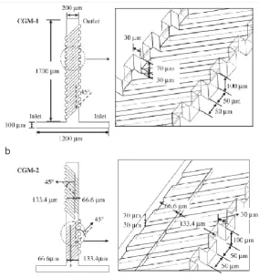
Figure 2.12 Schematic of the two channel designs of CGM (connected-groove micromixer) with not only bottom but also side grooves: (a) CGM-1 design; (b)
[image:32.595.177.462.372.677.2]19
[image:33.595.151.480.360.556.2]The design concept of SAR comes directly from the stretching-folding mechanism of chaotic advection. Hardt et al. [30] reported experimental and numerical results on the mixing performance with the SAR design mimicking the original concept of the stretching-folding scenario in the chaotic advection (Figure 2.13). Compared with the design with grooves on the bottom wall, this design guarantees almost uniform mixing characteristics over the whole cross section of the channel. A problem, of course, lies in the difficulty of fabrication. Lee et al. [31] proposed to use steps and partition blocks on the bottom wall of the channel (Figure 2.14) to establish the split-and-recombination function without fundamental difficulty in the fabrication process. Suh et al. [32] also presented a new channel design composed of a series of cross baffles. Clear evidence of stretching-folding action was revealed from both numerical and experimental visualizations (Figure 2.15).
Figure 2.14: (a) Perspective view of SAR mixer with steps and partitioning blocks on the bottom wall and (b) schematic illustration of mixing principle (from Lee et al.
[31]).
Figure 2.15: (a) comparison of the mixing patterns from numerical (left) and experimental (right) results for each section of the channel (denoted as (a), (b), (c)
[image:34.595.116.518.391.649.2]21
2.5. DROPLETS
The pressure-driven flow employed in most continuous-flow mixers, such as hydrodynamic focusing, alternate injection or the geometry-modification technique, inevitably suffers from a broad distribution in the residence time due to the parabolic velocity profile. The method of droplet or slug mixing has been developed to overcome this problem. Due to a strong surface-tension effect at the interface between the sample (occupying the droplet) and the carrier fluid (usually oil), the droplet always takes an isolated form such as a sphere or finite cylinder, and thus every fluid particle within the droplet must experience almost the same residence time. Another advantage in the droplet mixing is that the internal flow required for the mixing can be relatively easily created by a meandering channel.
Figure 2.16: A meandering channel with bumps on the outer side for use in mixing three kinds of liquids (from Liau et al. [33]).
23
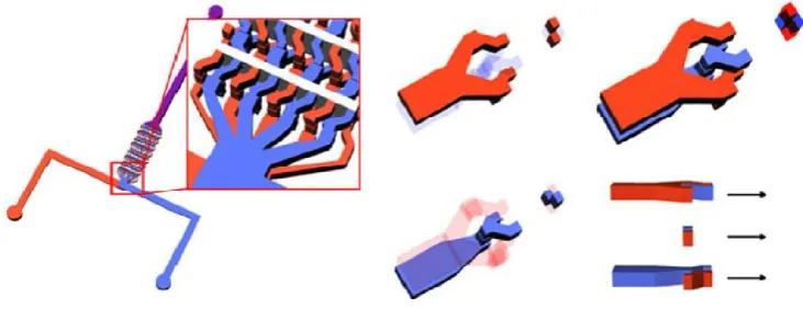
Figure 2.17: Coalescing of two droplets in a (a) side-by-side and (b) longitudinal arrangement. Mixing performance is plotted in (c): ■, mixing of dye and water in a side-by-side coalescence configuration; ●, mixing of dye and water in a longitudinal
coalescence configuration; ○, bleaching reaction in a longitudinal coalescence configuration. Here a low level of χ means a better mixing effect (from Sarazin et al.
Figure 2.18: A microchannel mixer with an air-inlet port to produce isolated droplets for better mixing (from Rhee and Burns [40]).
REFERENCES
[1] Jayaraj, S.; Kang, S.; Suh, Y.K. A review on the analysis and experiment of fluid flow and mixing in micro-channels. J. Mech. Sci. Technol. 2007, 21, 536-548.
[2] Falk, L.; Commenge, J.-M. Performance comparison of micromixers. Chem. Eng. Sci. 2010, 65, 405-411.
[3] Floyd, T.M.; Schmidt, M.A.; Jensen, K.F. Silicon micromixers with infrared detection for studies of liquid-phase reactions. Ind. Eng. Chem. Res. 2005, 44, 2351-2358.
[4] Nguyen, N.-T.; Huang, X. Mixing in microchannels based on hydrodynamic focusing and time-interleaved segmentation and experiment. Lab Chip 2005, 5, 1320-1326.
[5] Adeosun, J.T.; Lawal, A. Mass transfer enhancement in microchannel reactors by reorientation of fluid interfaces and stretching. Sens. Actuator. B 2005, 110, 101-111.
[6] Adeosun, J.T.; Lawal, A. Residence-time distribution as a measure of mixing in T-junction and multilaminated/elongational flow micromixers. Chem. Eng. Sci. 2010, 65, 1865-1874.
[7] Cha, J.; Kim, J.; Ryu, S.-K.; Park, J.; Jeong, Y.; Park, S.; Park, S.; Kim, H.C.; Chun, K. A highly efficient 3D micromixer using soft PDMS bonding. J. Micromech. Microeng. 2006, 16, 1778-1782.
[8] Park, H.Y.; Qiu, X.; Rhoades, E.; Korlach, J.; Kwok, L.W.; Zipfel, W.R.; Webb, W.W.; Pollack, L. Achieving uniform mixing in a microfluidic devices: Hydrodynamic focusing prior to mixing. Anal. Chem. 2006, 78, 4465-4473.
[9] Cieslicki, K.; Piechna, A. Investigations of mixing process in microfluidic manifold designed according to biomimetic rule. Lab Chip 2009, 9, 726-732.
[10] MacInnes, J.M.; Chen, Z.; Allen, R.W.K. Investigation of alternating-flow mixing in microchannels. Chem. Eng. Sci. 2005, 60, 3453-3467.
[11] Goullet, A.; Glasgow, I.; Aubry, N. Effects of microchannel geometry on pulsed flow mixing. Mech. Res. Commun. 2006, 33, 739-746.
[14] Leong, J.-C.; Tsai, C.-H.; Chang, C.-L.; Lin, C.-F.; Fu, L.-M. Rapid microfluidic mixers utilizing dispersion effect and interactively time-pulsed injection. Jpn. J. Appl. Phys. 2007, 46, 5345-5352.
[15] Sun, C.-L.; Sie, J.-Y. Active mixing in diverging microchannel. Microfluid Nanofluid 2010, 8, 485-495.
[16] Fu, L.-M.; Tsai, C.-H. Design of interactively time0pulsed microfluidic mixers in microchips using numerical simulation. Jpn. J. Appl. Phys. 2007, 46, 420-429.
[17] Lee, Y.-K.; Shih, C.; Tabeling, P.; Ho, C.-M. Experimental study and nonlinear dynamic analysis of time-periodic micro chaotic mixers. J. Fluid Mech. 2007, 575, 425-448.
[18] Chen, C.-K.; Cho, C.-C. A combined active/passive scheme for enhancing the mixing efficiency of microfluidic devices. Chem. Eng. Sci. 2008, 63, 3081-3087.
[19] Liu, R.H.; Stremler, M.A.; Sharp, K.V.; Olsen, M.G.; Santiego, J.G.; Adrian, R.J.; Aref, H.; Beebe, D.J. Passive mixing in a three-dimensional serpentine microchannel. J. Microelectromech. Syst. 2000, 9, 190-197.
[20] Stroock, A.D.; Dertinger, S.W.; Ajdari, A.; Mezic, I.; Stone, A.; Whitesides, G.M. Chaotic mixer for microchannels. Science 2002, 295, 647-651.
[21] Heo, H.S.; Suh, Y.K. Enhancement of stirring in a straight channel at low Reynolds-numbers with various block-arrangement. J. Mech. Sci. Technol. 2005, 19, 199-208.
[22] Kim, D.S.; Lee, S.H.; Kwon, T.H.; Ahn, C.H. A serpentine laminating micromixer combining splitting/recombination and advection. Lab Chip 2005, 5, 739-747.
[23] Xia, H.M.; Wan, S.Y.M.; Shu, C.; Chew, Y.T. Chaotic micromixers using two-layer crossing channels to exhibit fast mixing at low Reynolds numbers. Lab Chip 2005, 5, 748-755.
[24] Ansari, M.A.; Kim, K.-Y. Parametric study on mixing of two fluids in a three-dimensional serpentine microchannel. Chem. Eng. Sci. 2009, 146, 439-448.
[25] Howell, P.B.; Mott, D.R.; Fertig, S.; Kaplan, C.R.; Golden, J.P.; Oran, E.S.; Ligler, F.S. A microfluidic mixer with grooves placed on the top and bottom of the channel. Lab Chip 2005, 5, 524-530.
[26] Yang, J.-T.; Huang, K.-J.; Tung, K.-Y.; Hu, I.-C.; Lyu, P.-C. A chaotic micromixer modulated by constructive vortex agitation. J. Micromech. Microeng. 2007, 17, 2084-2092.
[27] Simonnet, C.; Groisman, A. Chaotic mixing in a steady flow in a microchannel. Phys. Rev. Lett. 2005, 94, 134501.
81
[29] Yang, J.-T.; Fang, W.-F.; Tung, K.-Y. Fluids mixing in devices with connected-groove channels. Chem. Eng. Sci. 2008, 63, 1871-1881.
[30] Hardt, S.; Pennemann, H.; Schonfeld, F. Theoretical and experimental characterization of a low-Reynolds number split-and-recombine mixer. Microfluid Nanofluid 2006, 2, 237-248.
[31] Lee, S.W.; Kim, D.S.; Lee, S.S.; Kwon, T.H. A split and recombination micromixer fabricated in a PDMS three-dimensional structure. J. Micromech. Microeng. 2006, 16, 1067-1072.
[32] Suh, Y.K.; Heo, S.G.; Heo, Y.G.; Heo, H.S.; Kang, S. Numerical and experimental study on a channel mixer with a periodic array of cross baffles. J. Mech. Sci. Technol. 2007, 21, 549-555.
[33] Liau, A.; Kamik, R.; Majumdar, A.; Cate, J.H.D. Mixing crowded biological solutions in milliseconds. Anal. Chem. 2005, 77, 7618-7625.
[34] Muradoglu, M.; Stone, H. Mixing in a drop moving through a serpentine channel: A computational study. Phys. Fluids 2005, 17, 073305.
[35] Tung, K.-Y.; Li, C.-C.; Yang, J.-T. Mixing and hydrodynamic analysis of a droplet in a planar serpentine micromixer. Microfluid Nanofluid 2009, 7, 545-557.
[36] Dogan, H.; Nas, S.; Muradoglu, M. Mixing of miscible liquids in gas-segmented serpentine channels, Int. J. Multiphase Flow 2009, 35, 1149-1158.
[37] Tanthapanichakoon, W.; Aoki, N.; Matsuyama, K.; Mae, K. Design of mixing in microfluidic liquid slugs based on a new dimensionless number for precise reaction and mixing operation. Chem. Eng. Sci. 2006, 61, 4220-4232.
[38] Wang, Y.; Kang, S.; Suh, Y.K. Enhancement of mixing in a microchannel by using ac-electroosmotic effect. In Proceedings of Micro/Nanoscale Heat Transfer Conf., Taiwan 2008; Paper No. MNHT2008-52142.
[39] Sarrazin, F.; Prat, L.; Miceli, N.D.; Cristobal, G.; Link, D.R.; Weitz, D.A. Mixing characterization inside microdroplets engineered on a microcoalescer. Chem. Eng. Sci. 2007, 62, 1042-1048.
[40] Rhee, M.; Burns, M.A. Drop mixing in a microchannel for lab-on-a-chip platform. Langmuir 2008, 24, 590-601.

![Figure 2.6: Distribution of species concentration in wavy-wall channels by (a) continuous injection, (b) pulsed injection with a certain period and (c) pulsed injection with the period double that for (b) (from Chen and Cho [18])](https://thumb-us.123doks.com/thumbv2/123dok_us/8775768.901352/28.595.244.391.66.284/distribution-concentration-channels-continuous-injection-injection-certain-injection.webp)