A
Unified
Framework
for
Two-
g
uard
Walk
Problem
John
Z.
Zhang
Mathematics and Computer Science, University of Lethbridge, Lethbridge, AB T1K 3M4, Canada
Copyright c⃝2015 by authors, all rights reserved. Authors agree that this article remains permanently open access under the terms of the Creative Commons Attribution License 4.0 International License
Abstract
We propose a unified framework to study the walk problem in a polygonal area by two collabo-rative guards. A walk is conducted by the two mobile guards on the area’s boundary. They start at an initial boundary point, move along the boundary, and may possibly meet together again at an ending boundary point. It is required that the two guards maintain their mutual visibility at all times. Depending the geometric properties of the polygonal area, a walk may or may not be possible. In this work, three versions of the problem, namely, general polygon walk, room walk and street walk, are characterized in a unified manner in our framework. One additional merit of our framework is its simplicity. Applications of the walk problem by two guards include military rescue, area exploration, art gallery surveillance, etc.Keywords
Visibility in Polygons, Two-guard Walk, Streets and Rooms, Visibility Diagram, Computational Geometry1
Introduction
Imagine that two guards walk collaboratively along the boundary of a simple polygon. In order to protect themselves, each guard is equipped with a vision device such that there is always a light beam between them, i.e., the two guards maintain their mutual visibility at all times. This can be implemented by installing a mir-ror on one guard while the other guard carries a device that can emit a beam and receive it when it is reflected by the mirror. Given a polygon, the two-guard walk problemasks whether it is possible for the two guards to start at a boundary point, walk along on its boundary while maintain their mutual visibility, and eventually meet together again.
Depending on where the two guards start and end their walk, the walk problem has three different versions. Astreet[6] is a simple polygon with two predetermined vertices, designated as the entrance and exit. The two guards start walking in the opposite directions from the
entrance along the boundary, while maintaining their mutual visibility. They may move backward from time to time, as long as each of them does not move beyond the entrance and the exit. The walk completes when they meet at the exit. A street is said to be walkableif it is possible for the two guards to conduct such a walk. Four variations – general walk, straight walk, counter walk, and straight counter walk – in a street are dis-cussed in [6]. The work contains numerous involved and tedious discussions to characterize the walkable streets under each of these variations.
Heffernan [5] propose a linear-time algorithm to check whether a street is walkable, by making use of complex data structures. Tseng et al.[18] consider the problem of finding all the pairs of entrances and exits that can make the respective streets walkable. Bhattacharya et al. [2] come up with an optimal algorithm for the same problem. In [4], Crass et al. study an∞-searcher in an open-edge “corridor”, which uses edges as the entrance and exit. An∞-searcher has a visibility of 360o[14].
The two-guard walk problem is also studied in the setting of rooms [11, 12]. A room is a simple polygon with a designated point on its boundary, called thedoor, which is like the entrance in a street walk. However, no exit is predetermined. The two guards start at the door and walk along the room boundary in the opposite direc-tions as in a street walk and eventually meet somewhere again [11]. It is required that no inside intruders shall escape the room through its door. A characterization for walkable rooms is presented in [11, 12]. In [3] a linear-time algorithm for checking whether a room is walka-ble is proposed, based on the characterization in [24], which is equivalent to the one in [11, 12]. Zhang and Kameda [23] present how to find all doors in a poly-gon such that the respective rooms are walkable and the work in [21] improves its complexity. A 1-searcher car-ries one flashlight to which its vision is restricted, as shown below. Some results in [9, 10, 15] examine how to search a room by a 1-searcher.
pur-pose of a search is to detect any intruders by eventually illuminating them, if possible. Among those models, there have been results for searching a polygon by a 1-searcher. For instance, a set of forbidden geometric patterns are introduced in [16, 17] to determine whether a polygon is 1-searcherable or not. Another set of for-bidden patterns are also proposed in [7] for the same problem. LaValle et al. [8] propose an algorithmic ap-proach for deciding searchable polygons by a 1-searcher. Some attempts on the polygon search by two 1-searchers can be found in [13]. Recent work [20] in the general polygon setting follows the same strain of the two-guard walk problem in streets and rooms and examines walks in polygons without any entrance (door) and exit. It presents a set of, though quite complex, forbidden pat-terns for rendering a polygon to benon-walkableby two guards.
In this work, we study the two-guard problem from a theoretical viewpoint. We tackle the walk problem in general polygons, rooms and streets under a unified framework. By making use of the framework, our char-acterizations of the three versions of the two-guard walk problem are simple and easy to follow. We also con-jecture that such simplicity would lead to complexity gains in some other related issues, such as designing and implementing efficient walk schedules.
The rest of the paper is structured as follows. In Sec. 2, we introduce the notation used throughout the paper and formally define the three versions of the two-guard polygon walk problem, i.e., general walk, room walk, street walk. We also introduce our unified frame-work, namely, the visibility diagram of a polygon. In Secs. 3, 4, 5, we present characterizations of walkable polygons for the three versions of the walk problem us-ing our framework. Finally in Sec. 6 we summarize our results and discuss some future work.
2
Preliminaries
2.1
Notation
Succ(r) Pred(r) r
B(r)
[image:2.595.46.224.498.658.2]F(r)
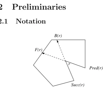
Figure 1. A reflex vertex.
We use Fig. 1 as an illustration. A simple polygon
P is defined by a clockwise sequence of distinctvertices numbered 1,2,· · ·,n, (n≥3), and nedges, connecting adjacent vertices. The edge between verticesuand vis denoted by (u, v). Theboundary ofP, denoted by∂P, consists of all its vertices and edges. The length of∂P is denoted as|∂P|, which is the sum of the lengths of the edges on∂P. (Naturally, we can consider P in a two-dimensional Cartesian coordinate system. The length of an edge (u, v) is then defined as the Euclidean dis-tance between verticesu andv.) We consider that ∂P
is part of the polygon, i.e., a polygon is composed of its boundary and its interior. The vertices immediately preceding and succeeding vertexvclockwise are denoted byPred(v) andSucc(v), respectively. For any two points
a, b ∈ ∂P, the open and closed portions of ∂P from a
to bclockwise are denoted by ∂P(a, b) and∂P[a, b], re-spectively.
In P, a vertex whose interior angle between its two incident edges is more than 180o is called areflex
ver-tex. Consider a reflex vertexr. Extend edge (Succ(r), r) toward the interior of P, and let B(r) ∈ ∂P denote thebackward extension point, where the extension leaves
P for the first time. The polygonal area formed by
∂P[r, B(r)] and the chordrB(r) is called theclockwise componentassociated withr, and is denoted byCcw(r).
Similarly, the extension of (Pred(r), r) determines the forward extension point,F(r), and thecounterclockwise component, Cccw(r), associated with r is bounded by ∂P[F(r), r] and the chordrF(r).
Two points,uandv, insideP are said to bemutually visible if the line segment uv is completely contained inside P.
2.2
The two-guard walk problem
Consider walking a polygon by two guards and let L
and R represent them (See below for more discussions on this.) respectively. We are seeking a time instant
T and two continuous functions, ℓ : [0, T] → ∂P and
r: [0, T]→∂P, such that
(a) ℓ(0) =r(0)∈∂P andℓ(T) =r(T)∈∂P;
(b) For anyt∈(0, T),ℓ(t)̸=r(t), andℓ(t) andr(t) are mutually visible.
Functionsℓ(t) andr(t), respectively, represent the po-sitions of L and R on∂P at t ∈ [0, T]. Depending on whether we have restrictions or not on ℓ(0) =r(0) (the starting point) and/orℓ(T) =r(T) (the ending point), we have three versions of the two-guard walk problem.
• For a general walk by two guards, there have no restrictions on the starting and ending points of the two guards. If time instant T exists, then we say that polygon P is walkable. In general, the two guards should walk in the opposite directions, though sometimes they may need to reverse their moves. Once they depart at some same starting point, they do not meet again, until, if possible, at an ending point eventually. For this reason, we des-ignate that, when the two guards depart, the first that moves in the clockwise direction isLwhile the other isR.
• For a room walk by two guards, we require that
ℓ(0) =r(0) =d, where dis the predetermineddoor and d ∈ ∂P[r(t), ℓ(t)] (t ∈ [0, T]). L walks along the boundary fromdclockwise whileR walks from
dcounter-clockwise. If time instantT exists, we say that the room iswalkable. We denote a room with
din polygonP as P(d).
• For a street walk by two guards, we require that
s and g are the predetermined entrance and exit, respectively. It is also required that ∂P(s, g) and
∂P(g, s) be weakly mutually visible, i.e., any point on∂P(s, g) should be visible to at least one point on∂P(g, s) and vice versa. L walks along∂P(s, g) clockwise while R walks along ∂P(g, s) counter-clockwise. Note that for street walk, there are some other variations, as shall be seen in Sec. 5. Again, if time instant T exists, the street iswalkable. We denote by P(s, g) a street with the entrances and exitg in polygonP.
It is easy to see that in all three versions of the walk problem, for any t ∈ (0, T), P is partitioned into two portions by the line segmentℓ(t)r(t) (i.e., the light beam between the two guards), such that one of them is always cleared of any intruders while the other iscontaminated1,
i.e., it contains intruders. We call (ℓ(t), r(t)), wheret∈
[0, T], a walk schedule. Essentially, a walk schedule for the two guards is to enlarge the cleared portion and shrink the contaminated one in polygon P, until the area of the latter becomes zero, i.e., the two guards meet again.
2.3
Visibility diagram
Given a polygonP, for two boundary pointspandq, we call ⟨p, q⟩ ∈ ∂P ×∂P a configuration [8]. ⟨p, q⟩ is a visible(invisible, resp.) configuration, if pand q are mutually visible (invisible, resp.).
We usex∈ ℜ2to represent a pointp(x)∈∂P, which
is at distancex−k|∂P| from the origin, wherek is an integer such that 0 ≤x−k|∂P| <|∂P|. According to this, given an x, there exists a k, such that x can be mapped to a point on ∂P. We thus can consider any
x ∈ ℜ as representing a point p(x) on ∂P. It should be noted that there are infinitely many real numbers
x ∈ ℜ that represent the same point p(x) on∂P, due to the different values k can take. In the following, we interchangeably usexand p(x) to refer a point on∂P, if no ambiguity arises.
B(r)
r
F(r)
r
0 Pred(r) Succ(r)
D +B(r) D D
F(r) +r
tip sides
S
[image:3.595.316.545.57.224.2]G
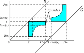
Figure 2. Visibility diagram (D=|∂P|).
Consider the infinite area between and including the lines y=x(thelineS) andy =x− |∂P| (thelineG), as shown in Fig. 2 [7, 8]. The visibility diagram (VD, for short) of polygonP, denoted asVDP, is drawn by
shading some portions in this area gray as follows: the point (x, y) is gray if the configuration⟨x, y⟩is invisible.
1This situation is not true for some other variations of street walk, as shown in Sec. 5. But this will not affect our discussions in the sequel.
2ℜdenotes the set of all real numbers.
0 1
6 7 9
2 3
5 8
10 12
13 11 4
(a) (b)
S
[image:3.595.94.263.555.662.2]G
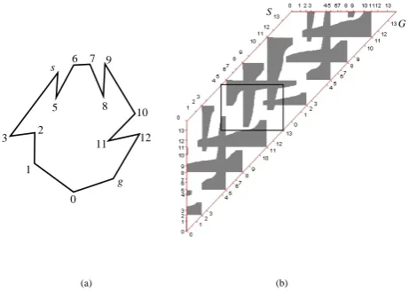
Figure 3. (a) An example polygon; (b) Its visibility diagram.
In Fig. 2, we show the gray areas due to reflex vertex r
in the polygon in Fig. 1. It is easy to see that the gray areas are caused by reflex vertices, due to which the invisibility in the polygon arises. In Fig. 2, the straight-edge sides of the gray areas touch either S or G. We call a gray area that touches S (G, resp.) anorthwest barrier (southeast barrier, resp.). Each barrier has four straight sides and a curved side (which is hyperbolic [1]). We also label thetip sidesof barriers.
As a further example, Fig. 3 (b) shows the visibility diagram for the polygon in Fig. 3 (a). In the diagram, we show vertex labels on lines S andGfor easy reference. Note that for a single configuration, there are an infinite number of points in the visibility diagram corresponding to it, as discussed above. That is why the gray areas in the diagram are periodic.
We now relate together the positions of the two guards on the boundary, the configurations, andVDP. Suppose
that we move the two guards along the boundary ofP. At any time t, L’s positionℓ(t) is represented by a real number x (corresponding to a boundary point, as dis-cussed above), measured by the distance from the origin (e.g., vertex 1). So isR’s positionr(t),y. These two po-sitions can be mapped into a configuration⟨x, y⟩, which corresponds to the coordinate (x, y), in VDP. On the
other hand, if we choose a point in VDP, it then
corre-sponds to a configuration, which designates the current positions of the two guards. Therefore, a point in the visibility diagram uniquely determines the current posi-tions of the two guards onP’s boundary.
The general approach to characterizing walkability in our unified framework is to consider the interactions among barriers inVDP. Note that, since we are
present-ing our characterization of walkable polygons in term of visibility diagram, though we may still use some polygon-related terms, they should be interpreted in the context of visibility diagram, if not specified otherwise. One such an example is that∂P(a, b) can be interpreted as the portion from point ato pointbonS orG.
2.4
Basic geometric patterns
poly-gons.
u v
F(v)
v u
v u
B(u)
(a)
S
G
(b)
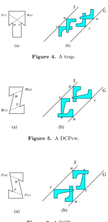
Figure 4. A trap.
u
v
u v
S
G
u
v
B(v)
B(u)
(a) (b)
Figure 5. A DCPcw.
u v
F(u)
F(v)
u v
u
v
(a) (b)
S
[image:4.595.77.251.73.430.2]G
Figure 6. A DCPccw.
2.4.1 Traps
Two reflex vertices,{v,u}, form a geometric pattern called a trap, if v /∈Ccw(u) and u /∈Cccw(v), as shown
in Fig. 4 (a) 3. We also show its counterpart in VD in
Fig. 4 (b).
2.4.2 Disjoint component pairs
Two reflex verticesuand v form aclockwise disjoint component pair(DCPcw, for short), ifCcw(u)∩Ccw(v) = ∅. We show in Fig. 5 (a) a DCPcw and in Fig. 5 (b) its counterpart in VD. The intersection between the north-west barrier (southeast barrier, resp.) due touand the southeast barrier (northwest barrier, resp.) duo to v
causes a bridge in VDP. The two bridges caused by a
DCPcw repeat periodically. Analogously, two reflex ver-ticesuandvform acounterclockwise disjoint component pair(DPccw, for short), ifCccw(u)∩Cccw(v) = 0. Fig. 6
shows a DCPccw and its counterpart in VD. Again, the barriers in a DCPccw cause two bridges.
In the following sections, we present general walk, room walk, and street walk by two guards in a consec-utive manner, with more and more restrictions on the starting and ending points of the two guards.
3Note that it might be true thatC
cw(u)∩Cccw(v) =∅.
3
General polygon walk by two
guards
We first consider general walk in polygonPby making use of VDP4. IfP is walkable by two guards, then
ini-tiallyℓ(0) =r(0) and configuration⟨ℓ(0), r(0)⟩is a point onS inVDP. When the walk is done,ℓ(T) =r(T) and |∂P(ℓ(0), ℓ(T))|+|∂P(r(T), r(0))| = ∂P. This means that configuration⟨ℓ(T), r(T)⟩is onG.
For any t ∈T, since ℓ(t) and r(t) are mutually visi-ble, the configuration⟨ℓ(t), r(t)⟩corresponds to a white point in VDP. All these white points, as time t goes
from 0 to T continuously, delineate a continuous path from S toGin some white area in VDP. On the other
hand, if there exists such a path, we can then count from time 0 at the configuration on S, map each point on the path to a configuration representing the current positions of the two guards on the boundary, and stop at time T at the configuration on G. All these mean that we have found a walk schedule for the two guards, i.e., the polygon is walkable.
Observation 3.1. Given a polygonP, for general walk,
P is walkable by two guards if and only if there exists a path in the white area which connects line S and lineG
in VDP.
At time 0, the two guards have to start at some same point on∂P, i.e.,ℓ(0) =r(0)∈∂P. We call it the walk starting point(WSP, for short). Beyond this point, the two guards walk along the boundary and, if possible, eventually meet again at awalk ending point(WEP, for short) at time T, i.e., ℓ(T) = r(T) ∈ ∂P. Not every boundary point can be used as a WSP or a WEP. In addition, if a WSP is selected, depending on the geo-metric properties of P, we may have to only select a WEP on some specific boundary portions. Also if we select a WSP, it might be that the two guards cannot finish their walk, though the polygon is walkable.
IfP is walkable, i.e., there exists a time instantT, we can let the time count down fromT to 0. The following is immediate.
Lemma 3.2. If polygon P is walkable by two guards starting at a WSP and ending at a WEP, it is also walk-able starting at the WEP and ending at the WSP.
Before proceeding further, we introduce some use-ful lemmas related to the simple geometric patterns in Sec. 2.4. In Fig. 4, the northwest barriers from v and
u intersect and form a triangular white area bordering
S. Any path starting at a point from∂P(v, u) onS, in order to reach G, has to go across the barriers due to
v and u, which make the two guards lose their mutual visibility. The same applies to the triangular white area borderingGas well.
Lemma 3.3. A point on ∂P[v, u] in a trap in Fig. 4 can be used as neither a WSP nor a WEP.
In Fig. 4, each point on∂P[v, u] is said to becovered by a trap. As for the pattern DCPcw in Fig. 5, we see that any path starting from S at a WSP from ∂P[v, u]
must end at a WEP on∂P[u, v], if the polygon is walk-able. The reason is that any path starting from∂P[v, u] has to stay within the two bridges due to the DCPcw. The same argument applies to the pattern DCPccw in Fig. 6.
Lemma 3.4. Suppose that a walkable polygon P con-tains a DCPcw in Fig. 5 or a DCPccw in Fig. 6. If we select a WSP on ∂P[u, v](∂P[v, u], resp.), then the corresponding WEP can only be on ∂P[v, u] (∂P[u, v], resp.).
3.1
Some related geometric patterns
3.1.1 Disjoint component pair couples
w u
v
B(w) B(v)
B(u) u
v
u v
w w
S G
[image:5.595.91.265.247.482.2](a) (b)
Figure 7. A 2DCPcw.
v w
u u
v w
S G
v u w
F(v) F(w) F(u)
(a) (b)
Figure 8. A 2DCPccw.
Two DCPcws can be coupled together. A DCPcw couple (2DCPcw, for short) consists of three reflex ver-tices, u, v, and w, such that {u, v} and {u, w} each form a DCPcw, as shown in Fig. 7. A DCPccw couple (2DCPccw, for short) is defined analogously to consist of three reflex vertices, u, v and w, such that {v, u}
and {w, u} each form a DCPccw, as shown in Fig. 8. It is obvious that the barriers due tou, v, andw cause some inaccessible area inVDP, as shown by the
follow-ing lemma.
Lemma 3.5. Suppose that a walkable polygon contains a 2DCPcw in Fig. 7 or a 2DCPccw in Fig. 8. Any point on
∂P[v, w]can be used as neither a WSP nor a WEP. In Fig. 7 (Fig. 8, resp.), each point on∂P[v, w] is said to be covered by a 2DCPcw (a DPCccw, resp.). Note that a boundary point can be covered by a trap and a disjoint component pair couple simultaneously.
3.1.2 Patterns τ and reverse-τ
Patternτ couples a DCPcw, formed by{u, r}, and a trap, formed by {u, v}, as shown in Fig. 9. Similarly, patternreverse-τcouples a DCPccw and a trap together, as shown in Fig. 10.
u v w
B(w)
F(v) B(u)
(a) (b)
u
w v
u v
w
v u w
u
v w
S
G
Figure 9. Patternτ.
v u w
F(w) B(u) F(v)
w
w
(a) (b)
u
u
v w
v u
u
v w
v
S
G
Figure 10. Pattern reverse-τ.
Lemma 3.6. If polygon P contains a pattern τ or reverse-τ, then it is not walkable.
Proof. We show the situation for pattern τ only, since the one for pattern reverse-τ is similar. From the barri-ers due to these vertices in VDP in Fig. 9 (b), it is easy
to find that no path in the white area inVDP is possible
from S toGwithout crossing barriers.
3.2
Characterizing walkable polygons by
two guards
In order to make our presentation easier we catego-rize polygons into two groups, those whose VDs do not contain any bridges, i.e., the polygons do not contain DCPcws and DPccws (Case I) and those whose VDs do (Case II).
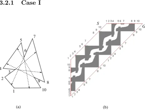
3.2.1 Case I
1 2
3 4
5
6 7
8 9
10
(a) (b)
S
[image:5.595.312.545.520.699.2]G
Figure 11. A non-walkable polygon under Case I.
the polygon is not walkable. This non-walkability of the polygon is shown clearly in Fig. 11 (b), where all points on bothS andGare covered by the three traps.
S
G
[image:6.595.79.249.100.228.2](2) (1)
Figure 12. Case I.
Theorem 3.7. Suppose that a polygon P does not con-tain any DPcws and DPccws. It is walkable if and only if there is at least a point onS (hence on G) that is not covered by any traps in VDP.
Proof. The necessity is due to Lemma 3.3. Let us deal with the sufficiency part. InVDP, we pick a boundaryp
as a WSP that is not covered by any traps. We attempt, in two steps, to construct a path starting atpwithin the white area inVDP fromS to G.
In Step One, initially starting fromp, we extend the path horizontally. Such an extension can be stopped by a northwest barrier from S. (Other situations will be discussed shortly.) We then turn the path downward along the barrier’s straight side, as shown in Fig. 125. We keep extending the path along the side. In this pro-cess, (1) if we encounter a northwest barrier (as marked by (1)) fromS again, this means that the two northwest barriers form a trap by whichpis covered, a contradic-tion; (2) if we encounter a southeast barrier (as marked by (2)), then the two barriers form a bridge, a contra-diction again. We should be able to reach the tip side of the northwest barrier. We then let the path follow the tip side. After that, we keep extending the path horizontally again. We then repeat the above process.
In the above process, if the path hits G, then the proof is done, with the path constructed. If the path hits a southeast barrier, we switch to Step Two. See Fig. 12 for the path after the first arrow. We follow the barrier’s boundary downward. We keep doing this. We may encounter another barrier. But this barrier must be a southeast one (no bridge inVDP). We then follow this
new barrier’s boundary. We may go back to the previous barrier or we may encounter a new barrier again. But we keep the path’s extension along the boundaries of those southeast barriers. Since there exists at least one boundary point that is not covered onG, eventually the path is led into that uncovered point. A path fromSto
Ghas been just constructed.
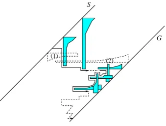
3.2.2 Case II
In Case II, a polygon contains DCPcws and/or DCPc-cws. According to Lemmas 3.4 and 3.4, there are some
5We only show the parts inVD
P that is relevant to our dis-cussions.
restrictions on the WSP and therefore the WEP of a walk.
For a DCPcw, if there exists at least one point on each of the two portions, ∂P(v, u) and∂P(u, v), that is not covered, we say that the DCPcw is aPath Construction Candidate (PCCfor short). We call it aPCC DCPcw. A similar definition also applies to a DCPccw. The intu-ition behind our proof is to focus the path construction within the area between the two bridges caused by a PCC DCPcw or a PCC DCPccw.
Theorem 3.8. Suppose that polygon P contains DCPcws and/or DCPccws and does not contain patterns
τ and reverse-τ. It is walkable if and only if there exists at least one PCC DCPcw and/or PCC DCPccw.
Proof. The necessity is due to the fact that, if there is no PCC DCPcw and PCC DCPccw in P, then according to Lemma 3.4, no path construction is possible.
For the sufficiency, we select such a PCC DCPcw (The situation for a PCC DCPccw is similar). Suppose that the PCC DCPcw is the one depicted in Fig. 5. We pick a pointp∈∂P(v, u), as a WSP, that is not covered on
S. From there, we attempt to construct a path to a point on∂P(u, v), as a WEP, that is not covered onG. Pointpmust be above reflex vertexvinVDP. The path
construction is conducted in four steps.
In Step One, we extend the path fromphorizontally. There are two possible situations during this extension to follow afterward.
(1) The path hits a northwest barrier due to a reflex vertexr1. We then let the path extend downward along
the straight side of the barrier. We claim that the path should be able to reach the tip side of the barrier. We use Fig. 13 as an illustration. During the extension, (i) the path should not hit a northwest barrier due to r2
again, as shown in Fig. 13 (a), since this means that the two northwest barriers form a trap, by which point p
is covered. After the tip side of the northwest barrier due to r1 is reached, we designate that path follow the
boundary of the barrier. We switch to Step Two; (ii) The path might encounter a southeast barrier due to a reflex vertexr3abovev on its curved side or tip side. For this
situation, we let the path extend downward along the boundary of the barrier. We switch to Step Two; (iii) In (ii), the southeast barrier might be due to a reflex vertex
r3 belowv. If this happens, we could have another two
bridges due to a DCPcw formed by reflex verticesr1and r3. We then have to consider whether such a DCPcw is
PCC or not and whether we need to apply the path construction again. We show this in Fig. 13 (b) for both (ii) and (iii), where the phantom but filled barrier is for (iii). Note that it might be true that reflex vertexr3 is v itself. Under that situation, we jump to Step Three below directly after the path reaches the tip side of the southeast barrier due tor3=v.
(2) The path hits the boundary of a southeast barrier due to a reflex vertex belowv, as shown in Fig. 13 (c). For this situation, we let the path extend vertically, until when it hits the curved side or tip side of a northwest barrier (similar to the northwest barrier due tor1 in (i)
r1
r3
r3
r2
r1
v v
u u
p
(c) Situation (2)
v v
u u p
v v
u u p
(a) Situation (1) − (i)
S
S S
G G
G
[image:7.595.258.531.48.587.2](b) Situations (1) − (ii) and (iii)
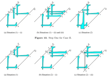
Figure 13. Step One for Case II.
r1
r3
r1
r2
v v
u u p
(a) Situation (1)
v v
u u p
v v
u u p
(b) Situation (2) − (i) (c) Situation (2) − (ii)
S S S
G G
G
Figure 14. Step Two for Case II.
(ii) in (1), or when it hitsS again, we restart the path construction with a newp.
In Step Two, we trace along the boundaries of all the relevant barriers without leaving them to extend the path, as detailed below. We claim that such a trace should be able to reach the tip side of the southeast barrier due to reflex vertex v. Note that during this extension, all the possible southeast barriers the path might encounter are due to the reflex vertices above v, as explained below, inVDP. Again, we have some
situ-ations to consider, as shown in Fig. 14.
(1) The path meets the boundary of a northwest bar-rier. We continue extending the path along the bound-ary of the barrier. Any northwest barrier preventing this would mean a trap by which pointpis covered, as indicated in Fig. 14 (a).
(2) The path meets the boundary of a southeast bar-rier due to reflex vertexr1. The path should be able to
extended to the tip side of this barrier. (i) If the exten-sion is hindered by the northwest barrier due to reflex vertexr2in Fig. 14 (b), this means that either the path
went across the barrier due tor2 before, ifpis belowr2
in the visibility diagram, or pis covered by a 2DCPcw formed by reflex vertices r1, r2, andu, ifpis abover2.
Both lead to a contradiction; (ii) The path meets the boundary of a southeast barrier. Such a barrier should be originated from a reflex vertexr3 belowu. However,
this means that reflex vertices r1 and r3 form a trap,
such that the portion fromuto v on lineG is covered, as shown in Fig. 14 (c), a contradiction to that we are considering a PCC DCPcw.
Going over the situations in (1) and (2) in this step, the path eventually reaches the tip side of the southeast barrier due tov, where we go to Step Three.
In Step Three, we extend the path along the boundary of the southeast barrier due to reflex vertexv. Such an extension should reach the tip side of the northwest bar-rier due to reflex vertexu. (1) It might hit the boundary
r1
v v
u u
p
v v
u p
u’u
(a) Situation (1)
S S
G G
v’
(b) Situation (2)
Figure 15. Step Three for Case II.
r1
r2
r2
v v
p u
u S
G
Figure 16. Step Four for Case II.
of northwest barrier due to a reflex vertex u′ below u, as shown in Fig. 15 (a). However, this northwest barrier intersect with the southeast barrier due to v. The path extension should be able to go around its tip side and go back to the southeast barrier due tov again. If there is another southeast barrier (due to reflex vertexv′, shown as the phantom barrier in Fig. 15 (a)) preventing us from do this, this means that the two reflex verticesu′ andv′
form a DCPcw. We need to consider our path construc-tion with this new DCPcw if it is a PCC. It is easy to see that this will not affect our proof, since all the above arguments are still valid. (2) The path might hit the boundary of a southeast barrier due to a reflex vertexr1
below reflex vertexu. Now the three reflex verticesr1,u
[image:7.595.122.500.49.309.2]in the theorem. This is shown in Fig. 15 (b).
In Step Four, when the path is at the tip side of the northwest barrier due tou, we let the path extend along the barrier. See Fig. 16. It might hit a northwest barrier originated from a reflex vertex aboveuinVDP. But this
renders no threat, since the path just needs to follow the barrier’s boundary. The path might hit a southeast barrier. Again it just follows its boundary. Note that during the extension of the path in Step Four, all the southeast barriers are due to reflex vertices aboveubut below v on line G. Since we are constructing the path within a PCC DCPcw, the path should be able to reach a point that is not covered on∂P(u, v) onG. One may argue that, when we extend our path along a southeast barrier due to reflex vertexr1, after the path goes around
its tip side, it hits a southeast barrier due to reflex vertex
r2. Suppose that the path has not reached any point that
is not covered (since otherwise the path construction is finished). Such a reflex vertexr2 can only be above u,
since otherwise the portion from u to r1 is covered by
the trap formed by reflex verticesr1andr2. The path so
far has not found any point that is not covered and the remaining part is covered by the trap, as indicated by the phantom barrier in Fig. 16. Thus the DCPcw is not a PCC, a contradiction. We can then just let the path follow the boundary of the barriers due to r1 and r2.
Eventually it reaches a point onGthat is not covered. We have just constructed a path from S to G within some white area inVDP.
The paths we have constructed in the proofs of Theo-rems 3.7 and 3.8 obviously correspond to walk schedules by the two guards. However, it can be also seen that such a path may have many unnecessary portions. It would be an interesting problem, by making use of the path construction idea in the visibility diagram, to build an “optimal” walk schedule. One optimality criterion could be the minimization of the walk distances by the two guards on the boundary. Another one could be the minimization of the number of turns the two guards need to do, i.e, changing their move direction. Since, when a guard reverses its move directions on the boundary, it consumes its battery energy, such a criterion would be interesting when designing and implementing mobile guards. In addition, we are also working on how to op-timally check the walkability for a given polygon, based on the characterization presented here.
4
Room Walk by two guards
We next consider walk in a roomP(d). IfP(d) is walk-able, then initiallyℓ(0) =r(0) =dand the configuration
⟨ℓ(0), r(0)⟩ is at (d, d) on S. When the walk is done,
ℓ(T) = r(T) and |∂P(ℓ(0), ℓ(T))|+|∂P(r(T), r(0))| =
∂P. This means that the configuration ⟨ℓ(T), r(T)⟩ is on G. For any t ∈ T, ℓ(t) and r(t) are mutually vis-ible, i.e., the configuration ⟨ℓ(t), r(t)⟩ corresponds to a white point in VTP(d). In addition, since at any time t ∈(0, T), d∈∂P[r(t), ℓ(t)], this means that no guard can move across the door at any time. The configuration
⟨l(t), r(t)⟩ is always within the area bounded byx≥d
and y ≤ d. It is easy to see that this bounded area is triangular. We call it thevisibility triangleforP(d) and
(a) (b)
S
G
0 1
6 7 9
2
5 8
10 12
13 11 4
[image:8.595.308.523.58.211.2]d
Figure 17. (a) An example room; (b) Its visibility triangle.
d u v
F(u)
F(v)
(b) (c) (d)
(a)
u v
F(u)
u d
v
v u
d u
v
B(v)
u v
B(u)
u v
F(v) B(u)
d
u v
B(v)
Figure 18. The patterns that trap the door point. (The two arrows in (d) need not intersect.)
denote it byVTP(d). We also call the left side ofVTP(d)
LSand the top sideTS.
As an example, for the polygon in Fig. 3, if we se-lect vertex 3 as the door, as shown in Fig. 17 (a), then according to the discussions above,VTP(3)is the
corre-sponding visibility triangle originated from vertex 3 in VDP, as shown in Fig. 17 (b).
Within this triangular area, the initial configuration for the two guards ⟨d, d⟩ is the only point on S. We call it the door point. Therefore, we have the following simple observation:
Observation 4.1. A room P(d) is walkable by two guards if and only if there exists a path in VTP(d) that
starts at the door point, stays in the white area, and ends on G.
We identify some patterns related to room walk. It is easy to see that many of the following patterns involve those basic patterns in Figs. 4, 5, and 6 in conjunction with the location of the doord. We abuse the notation a little. When the door point is considered, if one of the patterns in Fig. 18 appears inVTP(d), we say that the
door point is trapped. For points on G in Fig. 19 (a), we say that any point on portion ∂P[u, v] is covered. Similarly, in Figs. 19 (b), (c), (d), and (e), any point on portions∂P[d, v],∂P[v, d],∂P[v, u], and∂P[u, v], re-spectively, is covered.
The walkability of a room is characterized in the fol-lowing theorem.
Theorem 4.2. [24]A roomP(d)is walkable if and only if the door point is not trapped and there is a point on
Gthat is not covered in VTP(d).
[image:8.595.308.526.239.342.2]F(v)
v
d
(d) (e)
(a) (b) (c)
u v
v
v
u v
d
u v
u v
v u u
d v
F(u) B(v)
v
B(v)
d
B(u)
B(v)
d
[image:9.595.67.286.51.145.2]F(v) F(u)
Figure 19. The reflex vertex patterns that cover some portions onG.
(2)
(1)
r r g
(d,d)
1
2 G
TS
[image:9.595.104.248.187.327.2]LS
Figure 20. The sufficiency proof for room walkability.
could not reachG. We next prove the sufficiency. As-sume that the point (configuration) onGthat is not cov-ered is called g. We will show that, if the conditions of the theorem are satisfied, then we can always construct a path in some white area inVTP(d) that connects the
door point tog.
We use Fig. 20 as an illustration for our proof. Note that the visibility diagram in the figure is partial for clear presentation. Suppose that r1 ≺cw g ≺cw r2 on ∂P, where r1 and r2 are two reflex vertices and there
is no reflex vertex between r1 and r2. We first extend
the path horizontally toward LS, as marked by (1), in Fig. 20. This is the first step of our path construction. In this step, the path may encounter some barriers orig-inated from S or G that hinder it going further hori-zontally. Here we discuss the case where the path hits a barrier from S. The case for barrier from G can be treated similarly. We know that this barrier cannot in-tersect the southeast barrier due tor1, since otherwise gis covered inVTP(d). (The two barriers form the
pat-tern shown Fig. 19 (d), wheregis inside.) For the same reason, it cannot intersect any southeast barrier due to
r′, wherer′≺cw r1. Furthermore, any northwest barrier
originated from S intersecting this barrier would make the door point trapped. We are thus able to extend the path downward along the curved side of the barrier. When the path reaches its tip side, it then resumes going horizontally until it hits the next vertical barrier. Using this argument repeatedly, the path is able to reach LB ofVTP(d)eventually.
We then switch to the next step (as marked by (2)). At the beginning of this step, the path is at some point sufficiently close toLB. The path now goes upward along LB. In this process, the path might encounter horizontal barriers. But we first claim that those horizontal barri-ers should not be originated fromG. There are two cases we have to consider here. If it is a leftward bone due to
a reflex vertexr′ originated fromS, wherer′≺cwg, the
barrier must go across from G toLB in VTP(d). Since
the path is being extended upward, we know that the path should be above the barrier sometime before. This results in a contradiction, since it means that the path has gone across the barrier before. On the other hand, if the leftward bone is due to r′′, wheret ≺cw r′′, then
the fact that this barrier should go across fromGtoLB means that gis covered, a contradiction again.
For any barrier originated fromS, the path can then follow its curved until its tip side. Using the same rea-soning as above, we know that this barrier bone cannot intersect any barrier fromG, since, if so, the path was al-ready inside the region generated by the two barrier,LB andG, a contradiction to the fact that the path was gen-erated without crossing any barriers. By going around the tip side, the path follows the barrier leftward.
Now we consider the barriers originated fromS. But any intersection between some of these barriers and the current barrier means that the door point is trapped. So the path will eventually be able to reachLBin VTP(d)
again. Repeating this process, the path will finally reach the door point. By reversing the path we just con-structed and using the same argument in Lemma 3.2, the theorem follows.
Bhattacharyaet al.[3] propose a linear-time algorithm for checking whether a room is walkable, based on the characterization reported as above.
5
Street walk by two guards
Finally we apply our unified framework to street walk6. For convenience, on both ∂P[s, g] and ∂P[g, s],
whenLandRwalk fromstog, if pointais encountered before point b, we say thata is precedingb and denote it as a≺b.
In [6], four different variations of street walk by two guards are discussed. We reformat them under the con-text of our discussions.
• Thegeneral walkrequires thatℓ(0) =r(0) =sand
ℓ(T) =r(T) =g.
• Thestraight walkrequires thatℓ(0) =r(0) =sand
ℓ(T) =r(T) =gand functionsℓ(·) andr(·) be both monotonically increasing.
• Thecounter walkrequires thatℓ(0) =r(T) =sand
ℓ(T) =r(0) =g.
• The straight counter walk requires that ℓ(0) =
r(T) = s and ℓ(T) = r(0) = g, and functions ℓ(·) andr(·) be both monotonically increasing.
Function ell(t) (r(t), resp.) measures that the dis-tance from ℓ(0) (r(0), resp.) to the current position of the guard on L (R, resp.) at time t. It is easy to see that in the general walk and straight walk, the task of the two guards is to push any intruders inside the street from the entrance to the exit, whereas in the counter walk and straight counter walk, the task is to provide a way to separate intruders such that they cannot meet.
(a) (b) S
G
0 1
6 7 9
2 3
5 8
10 12 11 s
[image:10.595.45.276.60.224.2]g
Figure 21. (a) An example street; (b) Its visibility rectangle.
For all the variations, if at any timet∈[0, T],ℓ(t) and
r(t) are mutually visible, we say thatP(s, g) iswalkable. Previous characterizations [6] of walkable streets under the four different variations are involved. In contrast, by making use of our proposed unified framework, we attempt to reconsider them and obtain the equivalent characterizations in a much simplified way.
5.1
Visibility diagram of a street
We reconsider VDP in the context of street walk.
For P(s, g), we first have that ∂P[s, g] ×∂P[g, s] =
{⟨p, q⟩| p ∈ ∂P[s, g], q ∈ ∂P[g, s]}. It is obvious that these configurations are confined within a rectangular area in VDP. We call this area the visibility rectangle
for street P(s, g) and denote it by VRP(s,g). For
in-stance, for the polgyon in Fig. 3, if we select vertex 4 as the entrances and vertex 13 as the exitg, as shown in Fig. 21 (a), thenVTP(4,13)is the corresponding
visibil-ity rectangle imposed onVDP, as shown in Fig. 21 (b).
The top-left corner of VRP(s,g) corresponds to the
configuration ⟨s, s⟩ while the bottom-right corner cor-responds to the configuration ⟨g, g⟩. For VRP(s,g), we
call its top sideTS, right sideRS, bottom sideBS, and left sideLS.
By abusing the notion, we call a barrier intruding from the TS (originated from lineS) anorth barrier (NB), a barrier from the BS (from lineG) asouth barrier (SB), a barrier from the LS (from lineS) awest barriers (WB), and a barrier from the RS (from lineG) a east barrier (EB). It is easy to see that an NB and an SB never overlap while an EB and a WB never overlap.
Next we interpret street walk inVRP(s,g)using these
barriers. In a general walk, the two guards start at time
t = 0, where ⟨ℓ(0), r(0)⟩ corresponds to point (s, s) in VRP(s, g). IfP(s, g) is walkable, at any timet∈(0, T), ⟨ℓ(t), r(t)⟩is a visible configuration, which corresponds to a white point in VRP(s,g). The walk ends at time t = T, where ⟨ℓ(T), r(T)⟩ is at point (g, g). Imagine that, as time t changes from 0 to T, the points corre-sponding to ⟨ℓ(t), r(t)⟩ form a continuous path within the white area in VRP(s,g), which starts at (s, s) and
ends at (g, g). Conversely, if there exists such a path in VRP(s, g), then P(s, g) is walkable by the two guards,
since any point on the path is corresponding to a visible configuration, which can represent the current positions
of the two guards on∂P[s, g] and∂P[g, s], respectively. This is the main intuition that we will frequently utilize in our following discussions.
Consider then a straight walk by the two guards, who must not move backward along∂P[s, g] and∂P[g, s], i.e., both functions ℓ(·) and r(·) are monotonically increas-ing. For a straight walkable street, the path must run southeastward (the degenerate cases are the southward and eastward directions) but not in any other directions. As one example, if the path goes northward, it means that the right guard moves backward along∂P[g, s].
As for a counter walk, the left guard starts at s and ends at g while the right guard starts at g and ends at s. If we interpret this requirement within VRP(s,g),
then a path exists in the white area but starts at the configuration (s, g) and ends at the configuration (g, s). Furthermore, for a straight counter walkable street, the path can run only northeastward (the degenerate cases are the northward and eastward directions) but not in any other directions.
5.2
Characterizing walkable streets
In this section, we will derive the characterizations of different variations of street walk by unifying them under the framework ofVRP(s,g). As discussed in above,
the street walkability problem amounts to constructing a path inVRP(s,g).
5.2.1 The general walk and counter walk We consider the general walk and counter walk to-gether since our arguments for them are similar.
s
u v
g
v u (s,s)
[image:10.595.324.504.458.715.2](a) (b)
Figure 22. A northwest cross.
u v
g
g
(b) (a)
(g,g) v
u
Figure 23. A southeast cross.
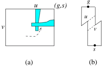
We redraw pattern trap in Fig. 4 in conjunction with the entrances in Fig. 22 (a), whose VD counterpart is shown in Fig. 22 (b). Within VRP(s, g), if an NB and
how we extend it, it is confined within the closed area formed by the TS, the LS, and the cross.
Analogously, the exitg may be involved with a trap, as shown in Fig. 23 (a), whose VD counterpart is shown in Fig. 23 (b). If an SB and an EB intersect, they form a southeast cross. Its existence VRP(s,g)results in that a
path cannot reach (g, g) because it cannot be extended into the closed area formed by the RS, the BS, and the cross.
(2)
SB (3)
(5)
(6)EB WB
(4)
(s,s) (g,s)
(g,g) (s,g)
NB (1)
EB
[image:11.595.93.263.173.287.2]SB NB
Figure 24. The illustration for Theorem 5.1.
Theorem 5.1. A street P(s, g) is walkable if and only if neither a northwest cross nor a southeast cross exists in VRP(s,g).
Proof. The necessity is obvious, according to the above discussions. So we only discuss the sufficiency. We use Fig. 24 as a reference. WithinVRP(s,g), we attempt to
construct a path from (s, s). We divide the construction into two steps. In the first step, we extend the path east-ward along the TS. There are two cases. The path hits the RS, in which case we switch to the second step, or hit an NB’s boundary, in which case the path is extended along it southward (as marked by (1) in the figure).
Such an extension should be able to reach the NB’s tip side. We need to consider two situations. (a) It hits a WB’s boundary (as marked by (2)). However, this is impossible, because then the NB and WB form a northwest cross; (b) It hits an EB’s boundary. We can then continue the extension along the EB’s curved side southwestward. We do not need to worry about any NB (as marked by (3)) intersecting with the EB, since this means that the path had been extended into the closed area formed by the TS, the RS, the NB, and the EB. Going around the EB’s tip side, we extend the path along the EB’s boundary eastward, attempting to reach the previous NB (from (1)). No SB can stop this (as marked by (4)), since if so, there existed a southeast cross. When the path hits the NB’s boundary, we extend it southward again.
We may need to repeat the above process, extending the path around the tip sides of some EBs. But eventu-ally, the path should be at the NB’s tip side (from (1)). After that, we extend the path eastward, until the path hits the next NB’s boundary, in which case we repeat the above process. If it hits an SB’s boundary (as marked by (5)), it is extended northwestward along its curved side. Any EB stopping this extension would mean that a southeast cross existed. On the other hand, any WB doing so would mean that the path had been extended into the closed area formed by the LS, the BS, the SB, and the WB. After reaching the SB’s tip side, the path
is extended again eastward until the next NB or SB. If it hits the RS, we go to the second stage.
We extend the path clockwise, along the RS of VRP(s,g)or the boundaries of EBs, attempting to reach
(g, g). The extension is always possible. It may en-counter an EB (as marked by (6)). But we can always go around its tip side and follow its boundary clockwise, by the similar reasonings as above. It is impossible to come across any WB. The path just constructed repre-sents a walk schedule for the two guards.
s u
v g
(a) (b)
u
v
[image:11.595.341.518.197.461.2](s,g)
Figure 25. A southwest cross.
g
u
v
s
(a)
(b)
(g,s)
u
[image:11.595.345.517.347.460.2]v
Figure 26. A northeast cross.
As for a counter walk, we need to construct a path connecting between (s, g) to (g, s). Let us call the inter-section between an SB and a WB asouthwest crossand the intersection between an NB and an EB anortheast cross, as shown in Figs. 25 and 26, respectively. It is easy to see that, this time,sis in conjunction with a DCPccw (Fig. 6) whilegis in conjunction with a DCPcw (Fig. 5).
WB WB
SB (1)
(2)
(3)
(4) EB
EB (5) NB NB
(g,s) (s,s)
[image:11.595.357.506.585.684.2](g,g) (s,g)
Figure 27. The illustration for Theorem 5.2.
Theorem 5.2. A street P(s, g) is counter walkable if and only if neither a southwest cross nor a northeast cross exists in VRP(s,g).
never hit an SB’s boundary (as marked by (1)) since this implies the existence of a southwest cross.
The path may come across an NB (as marked by (2)) but should be able to extend along its boundary south-ward to its tip side. Any WB stopping this (3) would mean that the path had been extended into the closed area surrounding (s, s). No EB intersects the NB, due to the absence of a northeast cross.
Going around the NB’s tip side, the path extends along the curved side of the NB toward the curved side of the WB. It is obvious that no EB (4) can prevent this. The path should be able to reach the WB’s curved side and then goes along it until the WB’s tip side.
After this, the path extends northward, until it hits the next WB, in which case we repeat the above process, or it hits an EB (as marked by (5)). We then argue that the path is able to reach the EB’s tip side, since we do not need to worry about any SB preventing this, which would imply that the path had been extended into a closed area surrounding (g, g) before.
The path then extends northward again. Eventually, it reaches the TS or an NB’s boundary. In the latter case, we can continue extending it clockwise around the NB’s boundary, until it hits the TS again or the next NB’s boundary. This is always possible. When the path goes southward to the NB’s tip side, no WB can prevent this since it means that the path had been extended into the closed area around (s, s). No EB can prevent the path from going northeastward to reach the TS or the next NB’s boundary, due to the absence of any northeast cross. Finally, the path reaches (g, s) and the theorem follows.
5.2.2 The straight walk and straight counter walk
s v
v1 2
g
(b) (s,s)
(a)
v v1
2
(g,g)
Figure 28. A Type-IS-pair.
(a)
(b)
u
u
s
g
1 2
(s,s)
[image:12.595.341.490.423.520.2](g,g)
u
1u
2Figure 29. A Type-IIS-pair.
Let us first consider the straight walk case. For con-venience, we will assume that the given street is already
determined to be walkable. For a straight walk, the path inVRP(s,g) must only run southeastward but not
in any other directions. Consider the relationship be-tween a WB, due to v1 ∈ ∂P[g, s], and an EB, due to v2 ∈ ∂P[g, s], where v1 ≺ v2. If the WB’s tip side is
to the right of the EB’s, a path should be at least at the WB’s tip side first before going southwestward until the EB’s, i.e., function ell(·) is not monotonic, shown in Fig. 28. We say that the WB and EB form aType-I S-pair, capturing the S-like relationship between their relative locations. Similarly, we say that an NB, due to
u1 ∈ ∂P[s, g], and an SB, due to u2 ∈ ∂P[s, g], where u1≺u2, form aType-II S-pair, if the NB’s tip side is
be-low the SB’s, as shown in Fig. 29. A path has to reach the NB’s tip side first and then climb up to the SB’s, which means that function r(·) is not monotonic. Theorem 5.3. For a general walkable street P(s, g)is straight walkable if and only if in VRP(s,g), neither a
Type-I S-pair nor a Type-II S-pair exists.
Proof. The necessity is due to the above discussions. In order to avoid the two barriers in each S-pair, at least one of the functionsℓ(· · ·) andr(·) is not monotonic. For the sufficiency, we start with an emptyVRP(s,g)without
any barriers. Let us connect (s, s) and (g, g) using a rubber band. We can imagine that the rubber band runs from northwest to southeast. It looks like a strip with the top and bottom borders and has an infinitely small width. We add NBs, EBs, SBs, and WBs, in that order, to it.
NB
EB
(s,s) (g,s)
(g,g) (s,g)
Figure 30. The rubber band and touching points.
Consider an NB we are adding in. It may or may not touch the rubber band at its tip side. If it does, it must be at the tip side’s left end point and there is a right angle between the rubber band and its tip side. This is shown in Fig. 30. After adding some NBs, a new NB may only make the rubber band protrude further south. We then continue by adding EBs. An EB may pro-trude the rubber band further west. If there is a touch between the rubber band and an EB’s tip side, the touching point must be the bottom end point of the tip side, as shown in Fig. 30. Note that the addition of an EB may make the rubber band detach from an NB’s tip side.
The only possibility that the rubber bandmaychange its direction is where it touches an NB’s or an EB’s tip side. Since the tip side from NBs and EBs only touch the top border of the rubber band, no matter how we add those barriers, they can only protrude the rubber band further south and west but keep its general direction running southeastward.
[image:12.595.52.267.447.765.2]north-eastward or to southwestward is to protrude it from the band’s bottom border. In particular, to change its di-rection to northeastward requires that the rubber band touch tightly both end points of an NB’s tip side. Simi-larly, to change to southwestward requires that it touch tightly both end points of an EB’s tip side. In both situations, the street is not straight walkable.
With this observation, we continue adding SBs and WBs. An SB may protrude the rubber band north while a WB may protrude it further east. Suppose that the street was not straight walkable. Then we must have situations observed above, i.e., (a) the rubber band goes tight around an NB’s tip side; and/or (b) the rubber band goes tight around an EB’s tip side.
If the situation (a) happens, it means that there must exist an SB whose tip side is higher than an NB’s, i.e., a Type-IIS-pair existed. This leads to a contradiction. Note that a WB cannot make this happen. The protrud-ing from a WB can only possibly make smaller the angle between the rubber band and an NB’s tip side, because of the absence of a northwest cross. As for the situation (b), there then must exist a WB whose tip side is to the right of an EB’s, which means that a Type-IS-pair was present. Similarly, the protruding from an SB can only make smaller the angle between the rubber band and an EB’s tip side, due to the absence of a southeast cross.
Changing the order of adding barriers to VRP(s,g)
does not affect our analysis, since we are given a walka-ble street and the only possiwalka-ble way to change the rubber band’s direction is to have opposite protrudings on its two borders.
After adding all the barriers, the rubber band delin-eates a path whose general direction runs only southeast-ward from (s, s) to (g, g), which completes the proof.
(s,g)
(g,s)
2
v
v
(a) (b)
v1
v2
1
[image:13.595.72.258.481.757.2]s g
Figure 31. A Type-IIIS-pair.
(a) (b)
(s,g)
(g,s)
2
u
u1
u1 u2
[image:13.595.91.263.641.748.2]s g
Figure 32. A Type-IVS-pair.
We now consider the straight counter walk and assume that the street is counter walkable. Let us introduce another two types of S-pairs. Consider a WB, due to
v1 ∈∂P(g, s), and an EB, due to v2∈ ∂P(g, s), where v1≺v2. If the EB’s tip side is to the left of the WB’s,
we say that the two barriers form a Type-III S-pair of barriers, as shown in Fig. 31. Any path to be constructed from (s, g) to (g, s) must reach the WB’s tip side before turning northwestward to reach the EB’s, i.e., function
ℓ(·) is not monotonically increasing. Similarly, consider an SB, due to u1 ∈∂P(s, g), and an NB, due to u2 ∈ ∂P(s, g), where u1 ≺u2. If the SB’s tip side is above
the NB’s, we say that the SB and the NB form a Type-IV S-pair, as in Fig. 32, due to which any path has to reach the SB’s tip side before going southeastward to the NB’s. Functionr(·) is non-monotonic.
Theorem 5.4. A counter walkable street P(s, g) is straight counter walkable if and only if in VRP(s,g)
nei-ther a Type-III S-pair nor a Type-IV S-pair exists.
Proof. We only sketch the proof for the sufficiency, since it is similar to the one for Theorem 5.3. Let us first connect (s, g) and (g, s) using a rubber band within VRP(s,g). The rubber band runs from southwest to
northeast and has an infinitely small width.
We first add NBs, which may touch the rubber band and stretch it further south. Note that an NB’s tip side touches the rubber band, if there is any, at its right end point. Next we add EBs. Those barriers may protrude the rubber band further west. Since the street is counter walkable (thus no northeast cross is present), the pro-truding can only reduce the angle between the rubber band and the NB’s tip side.
We then add SBs and WBs. When the rubber band touches the right end point of the tip side of an NB (say, due tou2), in order to change its direction to southeast,
it has to go tight around the tip side. The only situation that can make this happen is where the tip side of an SB (say, due to u1, where u1 ≺u2) is above the NB’s,
protruding the rubber band north and making it tight around the NB’s tip side, i.e., there was a Type-IV S-pair present, a contradiction.
There could be impacts from WBs on the touching between the rubber band and an EB’s tip side. If there is a touch between the rubber band and an EB (due to
v1), it must happen at the top end point of the EB’s
tip side. For the running direction of the rubber band to change to northwest, the rubber band has to go tight round the tip side. This only happens when there is a WB (due to v2, wherev1 ≺ v2) whose tip side is to
the right of the EB’s, protruding the rubber band east and making it tight around the EB’s tip side. In this situation, a Type-III S-pair existed, i.e., function ℓ(·) was not monotonic, a contradiction again.
It can be easily checked that the characterizations re-garding the four variations of street walk, i.e., Theo-rems 5.1, 5.2, 5.3, and 5.4, are equivalent to the ones in [6]. Furthermore, Heffernan [5] propose a linear-time algorithm to check whether a street is walkable under the four variations.