PERPUSTAKAA~l UTHM
A STUDY ON THE FABRICATION OF MULTI MATERIAL
3D PATTERNS USING INKJET PRINTING
TECHNOLOGY
by
MUSTAFFA BIN IBRAHIM
A thesis submitted in partial
fulfillment of the requirements
for the degree of
Doctor of Engineering
In the
GRADUATE SCHOOL OF COMPUTER SCIENCE AND
SYSTEM ENGINEERING
KYUSHU INSTITUTE OF TECHNOLOGY
JAPAN
KYUSHU INSTITUTE OF TECHNOLOGY
:\13STIv\CT
A Study On The Fabrication Of Multi Material 3d Patterns Using
Inkjet Printing Technology
By MUSTAFFA BIN IBRAHIM
I n addition to its application in media printing, inkiet printing IS becotning an increasingly attractive option for the distribution and patterning of materials for a wide variety of applications such as the fabrication of prototype for the manufacturing sectors. Recently' a rapid protol)'ping method for building parts layer-by-layer has led to interest in fabrication of protol)'pes with extra functionalil)' by inkjet printing. ;\ new system is expected which can produce assemblies composed of parts with more than one color or with more than one material. This study intends to utilize Java program to manipulate CAD design data and interface them \vith a modified commercial 357 -nozzle piezoelectric printer with experiments focusing on the drop positioning and arrangement required to fabricate a multi material 3D patterns. Functional fluid materials such as silver nanoparticle conducti\T ink was successfully printed using inkjet printing technology to directly write an electronic circuit. In order to study the parameters affecting drop formation of an inkjet printer, a single nozzle piezoelectric inkjet system was also dC\'eloped to study basic parameters such as \'oltage amplitude, firing frequency and fluid viscosity. The understanding of these parameters reactions gi\'es a broader \·iew on work in the fabrication of multi material 3D patters using inkjet printing technology.
-1 '/J;
Y:.:r. '/
H~1*iO)ffl~li~ft0I=D,\j;ljt::'tl:::' (: c'~ G<I~,f-1-i'ol-~
H:
J.jf, 0)1ft
fill: (:::.
~cfill:
~-it
0
=Ii
Wi
(:
L- --C I
*
1M
6"0
0) ~1'F
f t (:" ~FnJt:.
\" \
fflj~.r--...o)J;tffllJ'~lj. G h --C \" \ 0 0 JlJ:~, ~{'F.:c7";v ~@~<I-
0
t:.
0') O)-=Fl~(:L- --C
ffl\,,\Gh
--C~ t:.fl'I~@~=li1*i'i, -1 '/ J;Y:.:r. '/
l'l~~ ffl \" \--C~tRpt~i?J::'tc'ft<
~Im ~{t;IJDL-
t:.
~1'F6"0 O)@~(:::.r}H.\lJ' ~~--::l--C
~--C \" \ 0 0
-thlJ'~~Thli't~i)J:O);i:J7 --,\.:>t;J*4C't~\'JJX: ~
~'1 t:.r~t~,&~6'0
~ 1~0 =- C lJ' -r
~0 c;il5;t G h 00 =-
0)1iff1E
-r Ii
Java
i§~~c'1'FJJX: L-t:.7'P J;"7 A~ ffl\,,\--CC
ADc'1'FJJX:
L-t:.7"-!J
o)t*f'F.l\='-1
'/!J 7
.:r.-7-.O){'FJJX:~:f3=-ft\,,\ m~,&:O)l::°:r:.~/~-1 '/J;y:
.:r. '/
I-
7'
~'/!J
(JA';vtt
357
f~) ~eX@ L-
t:.
t
0) ~{<efflL- --C ,
1~tJ:O)t;j;jSj-~ ffl \" \t:.:s'L
ft@~ {:::,£,~ (: ft0 t;j*40)~c flli:~~ ~1T--::l
t:.o
~t:., :jY~lm'r1t;J;jSj-cL---C,
~~'r1t;J;jSjoc'Ll00j:F:T J*1i:-=t-~-1 '/ J;y:
.:r. '/
I-
=liWic'tttl:l L-
~t~m~@]\Fa
~tBl@1<1-0 =- (: {:::'JJX:J}] L-
t:.
0
-t
0)ftlH:::., -1 '/
J;Y:.:r. '/ HRfill:(:::'
J::
0
ii&+
illztiil
0)±'JJX:(:::.Jl0~~ ~o;t 0/'~7 j. -!J-rLl00tlHFn.l\='piM~?SZg,.)r:, t;J*4*6J3t{:::'~<}0~~~1T'3
t:.
0') (:::.,
~,/:;'i';v J A';VO)t:':r:.:./~-1 '/J;Y:.:r. '/
Ht~llit~1j1}'JJX:Lt:.
0 -t L-
--c,
-th G
0)/-\7
j.-!J
~t;~1'FL-,
~,~~ ~1T--::lt:.i11i*,
-1 '/ J;y:
.:r. '/ HsHrj
~ ffl \" \t:.
t~g,.)r:
0)H
:r,.;~ ~ ffl \" \t:.
:s'L 1t @
~(:::.
r;m
<) 0J::
~Z\" \
~~~7Jq~G h
t:.
0:h.·HI I*:k'¥=:k'¥=plt
~.~7-.~AW~ ~~~7-.~AI'¥=ft
£~*
.
mml
liJf1E£
820-8502
tFn[iliJ!JMkt~:m:k~)IIw-680-4
Phone: +81-0948-29-7786
Fax: +81-0948-29-7751
Table of Contents
~r\bstract ... ii
.t\bstract in Japanese Language ... iii
Lis t 0 f Figures ... ,-ii
Ijst of Tables ... xi
Acknowledgement ... xii
Chapter Page 1.0 Introduction ... 1
1.1 Overview on Fabrication of 3D objects using Rapid Prototyping Technology ... 3
1.2 Problem Statement ... 5
1.3 Research Overview ... 6
1.4 .t\im 0 f This Study ... 7
1.5 Structure of this Thesis ... 8
2.0 Literature Review ... 11
2.1 I\Iulti l\hterial Rapid Protot)'ping Technology O'·en·iew ... 11
2.2 Rapid Protot)'ping CAD Data Interface ... 13
2.3 Inkjet Printing Technology Overview ... 15
2.3.1 Drop-on-Demand (DOD) Printing Technology ... 16
2.3.2 Rapid Protot)'ping Using Inkjet Printing Technology ... 17
2.4 Single Nozzle Drop Generator.. ... 20
2.4.1 Numerical Simulations on Single Nozzle Piezoelectric Drop Generator ... 22
Conclusion ... 27
3.0 Methodology ... 28
3.1 The Inkjet Printing System ... 28
3.1.1 The Inkjet Printer ... 30
3.1.2 The Motorized Stages ... 31
3.1.2.1 The Stage Controller. ... 33
3.2 Manipulation of CAD Data In Ja"a Program ... 34
3.3 Integration of Inkjet Printer and Java Program ... 36
3.4 Single Nozzle Piezoelectric Inkjet System ... 36
3.4.1 Drop Ejector Construction ... 37
3.4.1.1 Piezoelectric Disc .Actuators ... 38
3.4.1.2 Fabrication of Ejection Aperture Nozzles ... 39
3.4.1.3 Drive Pulse .Amplitude and Shape ... .41
3.4.1.4 Pressure ControL ... 42
3.4.1.5 Imaging of Droplets ... 43
3.5 Conclusion ... 44
4.0 Inkjet Printing of Silver Nanoparticle Ink.. ... .45
4.1 Experimental Details ... 45
4.1.1 The Silver Conductive Ink ... 45
4.1.2 The Printer Ink Cartridge Replacement ... 48
4.1.3 Silver Ink Viscosity and Surface Tension IvIeasurement.. .. .49
4.1.4 Adhesion of Silver Nanoparticle Ink ... 51
4.1.5 Silver Nanoparticle Ink Conductivity I\nd Applicability .... 52
4.2 Experimental Results and Discussions ... 52
4.2.1 Silver Ink Viscosity and Surface Tension l'vIeasurement ... 52
4.2.2 Curing Temperature Effect on Adhesion ... 54
4.2.3 Silver Nanoparticle Ink Conductivity I\nd Applicability .... 54
4.3 Conclusion ... 57
5.0 Inkjet Printing Resolution Study ... 59
5.1 Experimental Details ... 60
5.1.1 Ink Drying and Spreading ... 61
5.1.2 Complement Printing Resolution Study ... 62
5.1.3 Fabrication of 3D Pattern \\!ith Complement Printing ... 62
5.1.4 Single Drop Deposition Resolution Study ... 63
5.1.5 Fabrication of 3D Pattern With Single Drop Deposition .. 64
5.2 Experimental Results ... 64
5.2.1 Ink Drying and Spreading ... 64
5.2.2 Complement Printing Resolution Study ... 66
5.2.3 Fabrication of 3D Pattern With Complement Printing ... 68
5.2.4 Single Drop Deposition Resolution Study ... 70
5.2.5 Fabrication of 3D Pattern With Single Drop Deposition .. 71
5.3 Discussion ... 73
5.4 C0nclusion ... 74
6.0 Single Nozzle Piezoelectric Inkjet Device Experiment ... 76
6.1 Experimental Details ... 76
6.1.1 Ca"ity Length Effect ... 78
6.1.2 Drop Velocity IvIcasurement ... 78
6.1.3 Variable Viscosity Deposition ... 79
6.1.4 Case Study on Direct Print Siker Conductive Ink on The Surface of 3D Part ... 79
6.2 Experimental Results ... 80
6.2.1 Cavity Length Effect ... 80
6.2.2 Drop Velocity lIcasurement ... 82
6.2.3 Variable Viscosity Deposition ... 84
6.2.4 Case Study Result.. ... 85
6.3 Discussion ... 89
6.4 Conclusion ... 90
7.0 Conclusions and Recommendations For Future \\'ork ... 92
7.1 Conclusions ... 92
7.2 Future Directions ... 94
GlossalT ... 96
References ... 102
List of Figures
Number Page
1.0
2.0
1.1 l'vIobile-Phone Evolution ... 1
1.2 Stereolithography Process ... 3
1.3 A I'vIoulded Interconnect Device (MID) ... 6
1.4 Research Placement ... 7
1.5 Structure 0 f The Thesis ... 10
2.1 2.2 2.3 2.4 ') " _.J 2.6 2.7 2.8 Pattern Depositions Using Hopper Nozzles ... 12
The rVIicro Stereolithography Process ... 12
Data Exchange Formats For Rapid Prototyping J\hchines ... 13
Continuous Inkjet Technology ... 15
Drop-on-Demand Printing Technology ... 16
Ink-Jet Technologies Map ... 17
3D Printer From Z Corp ... 18
ThetIDojet Printer From 3D Systems ... 18
2.9 Poly jet From Objet Geometries ... 19
2.10 The Inkjet Device ... 20
2.11 Droplet Generator Using Piezoelectric Disc ... 21
2.12 Single Nozzle Piezoelectric Inkjet Device Configuration ... 22
2.13 Pasteur Pipette Glass Body Drop Ejector ... 22
2.14 Ink-Jet Nozzle Ejecting 1\ Series Of Drops ... 23
2.15 Nozzle Geometry And A Typical Jet Configuration \'i/ith Symbolic Representation Of The Computational Grid ... 23
2.16 Piezoelectric Printhead By J\·Iicrofab Technologies Inc. ... 24
2.17 \'ilaveform For Piezoelectric Printhead By J\·Iicrofab Technologies Inc ... 24
2.18 Voltage Pattern For 1\ Single Pulse ... 25
2.19 Schematic Illustrations Of\"\1ave Propagation 1\nd Reflection Under A Single Voltage With tdwell X topt In An Open-Closed Squeeze Tube ... 26
2.20 The Comparison Of Simulated Ejection Sequences And Corresponding Experimental Observations ... 27
3.0 4.0 5.0 3.1 3.2 3.3 3.4 3.5 3.6 3.7 3.8 3.9 3.10 3.11 3.12 3.13 3.14 3.15 3.16 3.17 3.18
The Inkjet Printing System ... 28
IVIanipulation Of CAD Data In Java Program ... 29
Epson Printer ... 30
Sigma Koki I"vIotorized Stages ... 31
Sigma Koki l'vIotorized Stage Controller ... 33
Object Solid Graphic ... 34
Object STL Graphic ... 34
Object Slicing ... 35
Jm"a Program Conversion Result... ... 35
Single Nozzle Piezoelectric Inkjet System ... 37
l'vIicrofab Piezoelectric Inkjet Dev1ce ... 38
Piezoelectric Disc \,(!ith Alligator Clip ... 39
A Simple And Low Cost Setup To Produce A Conical Closed End On Glass Pipette ... 40
The Use Of Tungsten \\fire In Fabricating Aperture Nozzle .. 40
The Use Of Printer Nozzle Plate In Fabricating Aperture Nozzle ... 41
The Kenwood AG-203A Oscillator ... 42
The l'vIanometer Tube Pressure Control.. ... 43
Phantom V5.0 High Speed Digital Camera ... 44
4.1 The Silver Conductive Ink ... 47
4.2 IvIechanism of Low Temperature Sintering ... 47
4.3 Printer Ink Cartridge Replacement ... 48
4.4 The Ink Cartridge Chip ... 48
4.5 Portable Viscometer ... 49
4.6 Surface Tensiometer ... 50
4.7 Principle Of .Adhesion Test ],vIethod ... 51
4.8 Surface Tension l\Ieasurement.. ... 53
4.9 Temperature Effect On Viscosity ... 53
4.10 Curing Temperature Effect On Adhesion ... 54
4.11 Temperature Effect On Volume Resistivity ... 55
4.12 Temperature Variation Effect On Silver Conductive Ink ... 55
4.13 Printed Silver Conductive Ink ... 56
4.14 Line Before Curing ... 57
4.15 Line After Curing ... 57
5.1 - ? J._ Piezoelectric Printhead Configuration ... 59
The Inkjet Printing System ... 60
5.3 Complement Printing In-Between Nozzles ... 62
5.4 Integration Of JvIechanicalAnd Electrical Elements In A Part ... 63
5.5 Description of A Single Drop Coverage Area ... 63
5.6 The Overlaying of Drops In The X And Y Axis ... 63
5.7 Description of .'\ Rectangular Pattern ... 64
5.8 Description of 1"\ Pyramid Pattern ... 64
5.9 Drying Time ... 65
5.10 Ink Spreading ... 65
5.11 Ink Printed On Slide Glass ... 66
5.12 Ink Printed On Inkjet Film. ... 66
5.13 Complement Printing ... 66
5.14 Printing Resolution ... 67
5.15 Complements Printing ... 67
5.16 Complements Printing Surface Roughness ... 67
5.17 Layer Thickness ... 68
5.18 Layer Surface Roughness ... 68
5.19 Inkjet Printing Of Capacitor JvIodel.. ... 69
5.20 3d Profile Of Capacitor 1Iodel ... 69
5.21 Inkjet Printing Of Part \,\lith Capacitor Model ... 70
5.22 Surface Flatness On X Axis ... 70
5.23 Surface Flatness On Y 1"\xis ... 71
5.24 Surface Profile Of Rectangular Pattern ... 71
5.25 Surface Profile Of Pyramid Pattern ... 71
5.26 Countering The Ink Sinking Problems ... 72
5.27 Profiles On Countering The Ink Sinking Problems ... 72
5.28 Contact ,\ngle ... 73
5.29 Contact Angle Effect on Wetting ... 74
6.0 6.1 Piezoelectric Inkjet Device ... 76
6.2 Single Nozzle Piezoelectric Inkjet System ... 77
6.3 Internal,\ir Pressure ControL ... 77
6.4 Cavity Length ... 78
6.5 Dimension BST 768 (Breakaway Support Technology ... 79
6.6 Ca\1.ty Length Effect For The 30 ]'vIicron Diameter Nozzle ... 80
6.7 Ca\1.t)' Length Effect For The 100 1Iicron Diameter Nozzle. 81 6.8 Pulse Width Applied For Ca\-ity Length 60mm ... 82
6.9 Frequency Effect On Drop Velocity ... 83
6.11 Variable Viscosity Disposition For 30 I'vIicron Diameter
Nozzle ... 84
6.12 Variable Viscosity Disposition For 100 ]'vIicron Diameter Nozzle ... 85
6.13 Electrical Resistance of Silver Ink ... 86
6.14 Surface Of .ABS Part That \'/as Built Flat ... 86
6.15 Surface Of ABS Part That \'hs Built Standing ... 87
6.16 Silver Ink on ABS Part That \'/as Built Standing ... 87
6.17 Silver I nk on Polished l\BS Part ... 88
6.18 r-Iydrophilic Design ... 88
6.19 Silver Ink on I-I ydrophilic Design ... 88
6.20 Two Sample of Conductive Tracks on ABS Part ... 89
List of Tables
Number Page
1.0
2.0 3.0
4.0
5.0
6.0
1.1 Step By Step Demonstration Of Rapid Prototyping
l'vlanufacture Process ... 4
3.1 Specification Of The Printer ... 31
3.2 Specification for motorized stages SGSP 26-50 ... 32
3.3 Specification For l'vlotorized Stages SGSP 20-85 ... 32
3.4 Specification For Stage Controller ... 33
4.1 SilYer Conductive Ink Specification ... 46
4.2 SLA Resin Specification ... 56
5.1
-
') J._ Experimental conditions ... 61Overlaying distance ... 64
6.1 Frequency effect on drop yelocity ... 82
6.2 Fluid l\Iaterial Properties ... 84
Acknowledgments
I would like to thank my advisor, Dr. Hiroyuki Narahara for the continuous challenges and dynamic work environment he provided during my pursuit of this work. He fostered a creative freedom in the pursuit of this investigation, but also provided insight when necessary. Iv1y sincere appreciation also goes to Dr. Hiroshi Suzuki for his advices and financial support throughout my study. I would also like to show my appreciation of Dr. Hiroshi Koresawa for his professional support of my work.
This work would not have been possible without the assistance of other students in our research group; Suzuki Narahara Research Laboratory. rv10st importandy, I would like to offer my deep appreciation to Iv1r. Takayuki Otsubo for his contribution in the programming work for the printer and CAD data manipulation and I also appreciate the conversations and companionship of l',lr. Kojima lvIichio who is always there by my side throughout my study.
Finally, I would like to thanked my wife \'I/ahida for her unwavering support and constant encouragement all along my PhD journey. The prayers of my mother have also contributed to the success of my work. And of course to my sons ...
Fauzul Azim, Faruq Hanif and Fakhrull"\Iuaz ...
"f3qrr /iI' all/bil/olls!" Be al///liliOlIJ lIo/for 11IOI/~)' or Jc!/i.l'h {!~g/"{/l/di:::'<'I//<'I/I,
lIor jilr Ih(/I 1'1'(/IIC"-CCIl! lhillg Il,hi(h Il/<'I/ mil jllllle. Bc all//Jilioll"- jilr klloll'ler(ge, /or l~gh/c{)II.1'lIeJ.'" tllldjor the IIpliji ~()'Of{/" pmple. Be all//Ji!iollJ /or Ihe alla/1I1//1'II1 o( all I/Jal (/ 1//(/11 allgbl 10 /Je.
ThiJ lI'aJ Ihe lllt'J..-r!ge q/lf"lllitllll Smilh Clark, FirJI PreJidenl ~(
[-Iokkaido UII/m"Sil)' (F'om;er!y kIOIl'" as Sapporo Agriml!lIral College). - /3)' Palll I\Olllt/lld ! 9! 5.
MlISlqf(a Bill Ibra/;illl SII'\jlki Nara/;ara Researc/; I..aboralolJ' Deparllllenl ~/ klec/;tlllimII'!forllltllioll S riellCC alld TeclJllolog)'
J:;)'Ils/m IIIJlilllte
of
TeclJllolog)', 680-4 KtlJ1'(I'\jI, Ii'\jlka S hi, Fllklloka Ken, 820-8502 JapallCHAPT
E
R 1
1.0 INTROD
U
CTION
Th
market
i
changing
rapidly
.
The
"VUl!ler
illtoday's
competitive
mark tplac
ar
thos
comparu
that
can
bring innovative high
valu
product and ervice to the custom
r before their
competitor
do
s. L
t u
recall what a mobil
-
phone look d like twenty
year
ago? 5 y
ar ago? La
t 6
months
?
Yesterday?
ot to mention its shape, weight and
functionality
a
hown in igure 1
.1.
ow and in th
future
it
will
be even smaller, lighter and
can do much mor than a
pri
r m
bil
-
phone uch
a
the incorporation
of
camera audio video play r,
internet
acc s ,
location pin
-
p inters,
cheduler
and ev n a a ca h cr
dit
device
that
yo
u
can
pay
whatever you
bu
in a
convenient
sto
re
just
b
canning
yo
ur mobile
-
phone
which
is
kn
wn a
electronic-wall
ts.DynaT~-\ ceU phone, 1983
• lotorola, Inc.)
-
'
-l ell _ .
~
Sony Eocsson V800 3 phone, 2005
(A.rnazon.com)
Figur
1.1
:
M
bil
-
Phone
volution
Rapid advancements in computer technology
hav
given
life
to
th
udden
increa e
f
computer
-
aided design
(C
AD
)
related technologie
, which
b
y
their
speed
and aut mati
0,ar used to manufactur prototyp
s quickl
and at low
-cost. The advancement of manufacturing technologies is being driven by the need for automation, miniaturization, cost reduction and environmentally friendly manufacturing. In recent years, the competition to send manufactured products to the market has been the prime concern for manufacturers. They cannot afford to make mistakes and once the product is released, the incorporated technology and design must work. The route of the development project must be fast, efficient and one important criteria is that all possible errors in the project are revealed as early as possible such as in the design and testing stage. It is common sense that the sooner an error is revealed the cheaper it is to correct because the further we are in the project the more costs have already been paid - such as costs if the design must be changed.
l\Ianufacturing organizations use Rapid Prototyping which refers to the physical modeling of a design using a special class of machine technology to produce models and prototypes of injection-molded parts and metal castings products. Rapid prototyping acts as a lubricant that helps to smooth and streamline the product development process mostly to help improve time to market and as a visualization tool [1]. The Rapid prototyping industry has achieved much since its first commercial process which was presented at the A UTOFACT show in Detroit in November 1987, by a company called 3D Systems, Inc. During that time, the process was not very accurate and there are not many choices in terms of materials. Therefore, the parts obtained were considered prototypes; which is sometlling to look at and serves as a basis for discussion. Nowadays, there are more than 30 processes some of wllich are already commercialized willie others are scill under development in research laboratories. The accuracy of the parts produced has improved significantly, and the choice of materials is relatively large whereby users can choose suitable macllines and materials which suite their purposes or applications. The tenn "prototyping" is rather misleading since the parts or models being produced nowadays more frequently being used for functional testing or to derive tools for pre-production testing.
Yet, there are scill room for growth and need for further advancement. The next task is to study tllis technology and make it more efficient, develop a methodology to design and optimize components made of multiple materials to enhance their functionality by using an inkjet printing technology which is one of the Rapid Prototyping technologies used to fabricate 3D objects. Multi-material rapid prototyping refers to a process of fabricating a part consisting of more than one component material from Crill models layer by layer. The benefit is to develop lighter, stronger, smarter structural components using multi-material optimization.
2-1.1 Overview on Fabrication of
3D
object
using Rapid
Prototyping Technology
Rapid
proto typing i a
proc
that i
s
capable of converting a 3D C
D
d
igo into a physical object
b
man
f la
ye
r
-
b
y-
la
ye
r powder,
so
lid
or
liquid-ba ed manufacturing m th
d
[2].
he
technologie
have
also
be n called
"la
yered
manufacturing"
r" lid
freeform
fabrication"
.
In
mechanical and manufacturing
ngineering
,
rapid pro to
typing
is th pr ce
f building prototyp
obj
cts to evaluate whether a
prop
ed
d
ign
i
me ting the requirem nt in aspects
uch
as
hape
s, sizes,
fit and
form
functionality
and other
r
qOO
m nt
.
They enhance the ability of
d
e
igoer
and
ngine
r
t
tudy the
£;a ibility of a
product
and
locat manufacturing
probl m
early
in th d ign pha
.
Thi
g
r
atly reduce costs and the
tim
-to-mark
t f th pr
duct. urrent
rapid
proto
typing
y
tem
are
heavil
y
u
d
by manag r ,
engineer s
ur
g
ons, archit ct arti
t
and
individual
s
from
many
di ciplin
.
The nam
of
p
ecific
proce
e
them elve
ar
al
often
u d
a yn
nym for th
ntire field
of
rapid proto
typing. Among
the
e ar
tere
lithography
(
LA
for t
r
o
lith
graphy apparatu) as
s
hown
in
Figur
1.
2
el cti
e
la
e
r
int ring
(
L
)
,
fu
e
d depo ition modeling
D
1)
lamin
at
d bj
ct
manufacturing
,
three
dim
n ional printing
(
3DP
)
and
many
th rs
.
Each of
the
techn
logi
a
nd the man
y
other
rapid
pro
to
typing process
s
ha it
ow
n
s
tr ngth
and weakn
e
but th ba ic
fabrication c
nc pt ar almost
th
e same
as
h
wn
in
Table
1.1
He dLa er
~O
weep r
~Blade
I
,
~---'
1-
ZAxi
r
Ii:!~~
r;
e
====:.J
P
artially
--u-
---=:;?C
=====~
~
E
le
ator
orm
d
bi
ect
~---.- ---~
l
Fortn
d
Object
Figure
1
.
2:
tr
O
litl1
graphy
Pr c
-
3
Tabl
1.1
:
t p
B,
rep Demontranon
f
RapId Prororyping \lanufactur
'
Pr ce
tage
1
Detail
D
19n 1created u mg a 3
modelin
sofp-var
uch a
'
lid
\\'rk , Pr
-<
ngm r,
rugrapruc, adceus and tc
..
Th
3D m dell pre
-
proc
d and
converted lUto tandard triangulational
languag
(
11..
-
11..
fil
c nn ct the
2
urface of th model in an arra, f
triangl
and c nit of the
:x,
Y
and
Z
rdinar
of th
thre v rtic
f
each
urface triangle
)
Th RP pr c
build the part up In
layer of mat nal from th bottOm. Each
layer
i
automaucally b nd d t
th
larer
b low and th pr ce
i
r p ated until
the part
1built. Thi pr ce
of b ndlng
3
i
und rtaken
10diff, r nt way [, r th
Yari
u mar
rial
that are being u ed but
4
include the
uf
U
ltra\'1ol
t(
C
~la r, arb n DlOxid
(
02
)
la er , heat
en itive glue and m lung the matenal
it
If
.
Th part are r m \
'
ed from the macrun
and po t proc
ing operati n take
plac ,
dl
.
may b
to add extra trengthto th part
by
filling proc
"Old, firu h
dl
curing
f
a part r t hand fini
-
h th
part
to [he d 'trd 1
,
"
e1
-1.2 Problem Statement
In August 3,J 2006, a \'\1all Street Journal article, "3D Printers Reshape World of Copying," is acknowledging the business value on the innovation of the rapid prototyping technology which can fabricate models quickly [3]. Terry \,\iohlers, president of \,\iohlers .Associates, a market research firm (www.wohlersassociates.com). says that among dle fastest-growing segment of the rapid-prototyping industry which had revenues of S809 million in 2005, up from an estimated S705 million in 2004 is the 3D printing technology which create physical models from computer-aided design (Ci\D) data by using an inkjet printing technology.
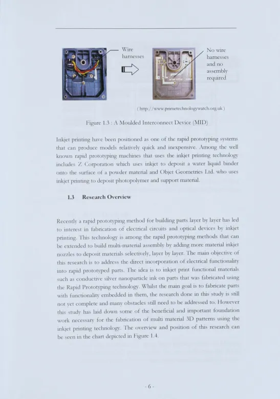
E,-cn though inkjet printing technology has been used to fabricate 3D strucrures or models, parts produced by the commercially available rapid proto typing systems are made of a single material. The multi-color 3D printer from Z Corporation only prints colors on surfaces - the material beneath is still the same as dle modeling material. In other rapid prototyping systems, nrious parts are built independendy using different colors and then assembled at a later stage. A new system is expected which can produce assemblies composed of parts with more than one color or widl more than one material. With this capability, some post-processing of rapid prototyping such as assembly, bonding, welding and painting can be eliminated. Figure 1.3 shows a component that was made using 3-D moulded interconnect devices (3-D l\IIDs). A moulded interconnect Device (MID) is defined simply as:
" ... all il!/edioll 1lI0llided plaJ/ic .wuJ/rate JI,hich illcorporales a cOlldllelil'e (i,.mil pallem, alld ilitegrateJ boll; mechallical alld electrical/lllldioIlJ."
Source: l\IIDIA (Molded Interconnection Device International Association)
3D l\IIDs are plastic mouldings that incorporate, or have on their surface, an integrated conductive pattern. As such they represent the fusion of mechanical and electrical functionally into one integrated component. MIDs often utilise three-dimensional circuitry; a circuit pattern widl several planes allows better circuitry spacing, as well as the potential for integrated switches, connectors and buttons. MIDs can also reduce the number of components and cost by embedding fearures such as connectors, wire harnesses or lamp-holders within a single device. In addition they can be designed to be self-supporting thus eliminating any requirement for mechanical parts needed to support the circuit boards. Through reducing part numbers, MIDs save space and shorten assembly time
-Wire
haroe
e
harnesse
o WlIes
and no
as embl
required
[image:20.558.1.548.31.809.2]( http://www.primetechnologywatch.org.uk )
Figure 1.3
:
Moulded Interconn ct Devic
n
D
)
Inkj
t
printing have b n po ition d
as on of
the rapid proto typing
y
t m
that can
produce model relatively quick
and
in
xpen
iv
.
Am
ng th
well
known rapid
prot
t
y
ping machine that u
e
the inkjet printing t
chnology
include
s
Z
orporation which
u
e
s
inkjet to dep it
a
water liquid binder
onto
the urface
of a
powder material
and
bjet Geom tri
Ltd
.
who
use
inkjer
printing
to
d po it photopol
y
mer
and support
material
.
1.3 Re
se
arch O
ve
rview
Rec ntl
y
a
rapid prot
typing
meth d for building parts lay r by layer ha led
to inter t in fabrication of electrical circuit and
ptical device b
y
inkj
t
printing
.
Thi
s
technology is
among th rapid prot typ
i
ng method that
can
be xtended to
build multi
-
material
assemb
l
y
by
adding
m re matenal inkj
t
nozzl
to
dep it materials
s
lectively layer by lay
r.The main
obj ctive of
thi
r
earch i to addr
the direct incorporation
of
electrical functionality
int
rapid pr
t
typ
d parts
.
Th
id
a
i
to
inkj
tprint functional materials
s
uch a conducti e
s
ilver nanoparticl ink n parts
that wa
fabricated u ing
the Rapid
Pro to typing
technology
.
\Vhil
t th main
goal
i
to fabricate parts
,vith functionality embedded
in them th re
earch
don in thi
tud i
till
not
y
t omplet and
man
y
bstacles
still
need to b
addres ed
to. How
ver
thi
s
tud
y
ha laid d
wn om of the
b neficial
and
important foundation
work
neces
ar)' for
th
fabrication
f multi material 3D patr ro u ing the
inkjet
printing technology
.
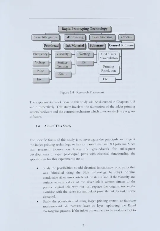
Th
v
rv1and po ition
of
thi
re
earch
can
be
n
in
the
chart
depicted
in Figure
1.4
.
-Rapid Prototyping Technology
tereolithography
Voltage
[image:21.558.7.546.21.798.2]Elc ...
Figure
1,-1.
:
Re
earch
Plac m nt
Th
xp
rim ntal
\Vrk d n in
till
_
tudy will
b
eli
cu
din hapter
-+
5
and 6 r
p
cuvely
.
Th.i
tudy
involve
th fabtlcau
n f the 111kj t printing
sy
tern
hardware and
th
c
ntr
1
mechani
s
m
wllich
111vol
e
th Java pr ram
ftwar
.
1.4
Aim
ofThi
tu
d
y
h
P
cific
~cu
f thi
tud
1St 111
e
Uat th principals and xploit
th inkj t pnnung technology
tfabncat
multi mat rial 3
tI:u
re
'
arch
t
cu
on
la 111
th
gr
undw rk
denl pment in rapid pr totyp d part
with
lectncal
p
clllc
a1ffi ~r
thl
.
xperim
n t
ar
t
:
pa tt rn
.
ince
t
r
ub quent
functi nality, th
•
t add
el ctncal
fun
u nahly nt part that
wa
fabricated
u 111g th
LA t chn 1
gy
b
ink, t pnnung
c
nducti,
'
il
r nanoparticl 111k nit urfac
.
If th
vi
co ity
and
urfac t
n i n alue
.
f the
il,
'
r 111k i
aim
t imilar t
th
r
ong111al
mk,
wh
n
t ju
tr pIa
th
original
ink in
th
cartridg with
th
ilv r ink
and
inkj t print the 111k t mak
som
clrcuitry?
•
tudy
the p
ibillne
f u 111g 10k, t printing
y
t m
t
fabncat
multi
-
mat nal
3D
part rn
s
la
er
b
layer r phcanng th Rapid
Pr t
typing
pr
c
s.
Ifth
111kj t pr111t r
wr to be u d
a a
to 1 t
-•
•
fabricate 3D patterns, what kind of infonnation or data is needed to be sent to the printer command language that operate the printer? The manipulation from CAD design data fonnat to a fonnat that
the inkjet printer can understand and function to fabricate multi-material 3D patterns layer by layer.
Study the inkjet printer fluid drops arrangement resolution needed to realize the fabrication of multi-material 3D patterns. The inkjet printer was design to print text or image of 3D patterns on surfaces such as paper or other media but is the resolution enough for the fabrication of 3D patterns? Can the inkjet printer drops arrangement be manipulate so that a required pattern such as flatness and denseness of drops be controlled?
Study the capabilities of drop on demand inkjet to deposit variable material by using a single nozzle drop generator. In order to deposits fluids with various characteristics, the parameters which are affecting the drop generation must be understand. \,\'ith the utilization of a single nozzle piezoelectric inkjet device which function similar to the principal of the inkjet printer, the capabilities of a drop on demand inkjet printer to deposits variable fluid materials can be achieved.
1.5 Structure of This Thesis
This thesis has been organized in 7 chapters whose content are outlined as follows:
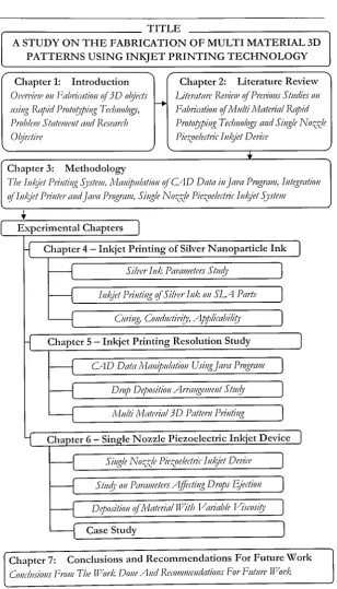
Chapter 1 which is this chapter defines the overview of fabricating 3D objects using the Rapid Prototyping Technology, statement of the problem and objecti\Ts of the research to be undertaken.
Chapter 2 provides the literature review and composed of four major sections. Multi material rapid proto typing technology overview, Rapid prototyping CAD data interface, Inkjet printing technology overview and Single nozzle piezoelectric inkjet system. IvIulti material rapid prototyping technology overview details ,vork perfonned to date in the fabrication of multi material structures using the rapid prototyping concept. The Rapid proto typing Ci\D data interface presents some of the work done on manipulation of CAD data fonnat in order to fabricate multi material 3D objects. The Inkjet printing technology overview defines the concept of the inkjet printing systems emphasizing on the drop on demand printing technology and fabricating 3D
8-objects using the inkjet printing technology. Lasdy a section on generating droplets using a single nozzle piezoelectric systems is included. This section offers an independent study on fluid materials and printing parameters for the piezoelectric inkjet device.
Chapter 3 presents the methodology used in the study which start firsdy with the inkjet printing system developed to print 3D patterns. This section explains the modification of a commercially available desktop inkjet printer, the motorized stages used for the X, Y and the Z axis and the motorized stages controller utilized in the inkjet printing system. The manipulation of CAD data using Java program was included and work on the integration of the inkjet printer and Java Program was also described in the later section.
Chapter 4 shows the experimental work done on the inkjet printing of conductive silver nanoparticle ink. This sections explains the experiments done on measurement of the viscosity, surface tension, adhesion and also the electrical conductivity. The experiment on inkjet printing of the ink on SL\ parts was also explain in this chapter.
Chapter 5 explains the experiment done to study the inkjet printer resolution. This involves the experiment on complement printing in-between the print-head nozzles which is 144 micron apart and also experiment on single drop deposition. This sections also shows the results on the work on the printing of 3D patterns using the inkjet printer.
Chapter 6 describes the experimental work on the fabrication of a single nozzle piezoelectric inkjet system developed to study the piezoelectric inkjet parameters affecting the drop generation of fluid. Some critical parameters such as fluid cavity length, amplitude voltage and fluid material with variable viscositT and surface tensions value were experimented so that the capability of inkjet printer to deposits functional fluid material can be understood. This chapter also explains a case study done on fabricating conductive tracks on ABS parts that was built by a FD1'vI Rapid Prototyping machine using the single nozzle inkjet system by controlling the motorized stages.
The final chapter presents a review of the research goals and provides a summary of the results obtained from the investigation. This chapter also provides recommendations and suggestions for future research to continue this area of research. Figure 1.4 shows the structure of this thesis.
-TITLE
A STUDY ON THE FABRICATION OF MULTI MATERIAL 3D PATTERNS USING INKJET PRINTING TECHNOLOGY
Chapter 1: Introduction Chapter 2: Literature Review
OI'm'ieJI' 011 Fa/Jlimtioll ~r 3 D o/jed.r
1-+
Ljteratlln: ReJ!ieJII ~r Prcl,iollS Stlldies 011 IIsillg Rapid Proto!Jpillg Ted}//oloJ!)', Faurimtioll if}.1l1lti Material Rapid ProblelJl StatelJlmt alld Reseanb Protol)pillg TedJ/loloJ!)' alld Sillgle No::::.:de Oljedil'e Pie::::.oelecllic Ill/gef DeJ,ice--Y. Chapter 3: Methodology
Tbe III/g'et Plilltillg Sj'stelJl, Malliplliatioll ~r CAD Data ill jal'tl P,vgralJl, Illtegratioll ~r IlIkjet Pn'lIter alld jal'tl Program, Sillgle No::::.:de Pie::::.oeledrir IlIkjet Sj'stem
E:~,:perimental Chapters
I
H
Chapter 4 - Inkjet Printing of Silver N anoparticle Ink~L_ _________ S_I_h_~r_I_I_lk_o_l)_a_ra_Il_1e_te_r._J_S_h_10~' ________ ~I
~L_
____I_lIk~9_'e_t_1)_n_il_h~I~~O~~r_S_I_h_~_r_1_1k_,_0_1I_S_l.
__~_P_a_r._u
____~J
~ ~'---_ _ _ _ _ Clllillg, COlldlldil,il)', /lpplimuili!J' - J
J
H
Chapter 5 - Inkjet Printing Resolution StudyJ
I-f
C,1D Data Malliplliatioll Usillgja/'{/ PlvgramJ
I-f
Drop Depositioll AmlllgemCllt St1l0'J
l---{
Mlliti Matoial 3D PailI'm PrilltillgI
l
Chapter G - Single Nozzle Piezoelectric Inkjet DeviceJ
r-l
Sillgle No::::.;)e Pie::::.oeledlir IlIkjet Del'iceJ
H
Stlllb' 011 ]Jammetm /~((edillg Drops Ejee/iollI
H
Depositioll ~rl\laferial If/ilb f/{l!iaule Viscosi!J'J
l---{
Case StudyI
Chapter 7: Conclusions and Recommendations For Future \Vork
[image:24.595.150.459.139.679.2]COllcillSiollS From Tbl' ll/ork DOlle A lid RecommClldatiolls For Flltllre 1f70rk
Figure 1.5 Structure of The Thesis.