proceeding of National Conference of Electric and Electronic Engineering 2012
Modified LEACH Algorithm for Prolongation Network
Lifetime in Wireless Sensor Network
Saltihie Bin Zenill*, Jiwa Bin Abdullah2
'Electrical Engineering Department, PMU 'Faculty of Electric and Electrical Engineering,
Universiti Tun Hussein Onn Malaysia
1. Introduction
Wireless Sensor Network (WSN) is widely used to create a smart environment that relies on sensory data from real world. The application of wireless sensor network has fulfill nowadays needs by providing a facilities to monitor a physical and environmental conditions, such as temperature, sound, vibration, pressure, motion and pollutants. A smart environments is relies on sensor network to gathering an information, whether in building, shipboard, transportation system automation, habitat monitoring, healthcare monitoring, home automation, traffic control, or elsewhere [I] [5]. A smart sensor used in WSN is a combination of sensing, processing and communication technologies.
The study done by [2] stated that network lifetime is a key characteristic to evaluate a sensor network. The effectiveness of WSNs is depending on the sensor in the network. If the sensor node considered 'alive', it then can perform a duty to sense, communicate and process information (temperature, humidity etc), but not after that. There are two major factors that affect the network lifetime: how much energy it consumes over time and how much energy available for its use. The proposed technique to deal with network lifetime called clustering is an important method, and a good performance WSNs is highly dependent on energy- efficient clustering routing algorithm [6]. The development of a clustering-based hierarchy protocol that optimizes the energy-efficiency in WSNs is called Low- Energy Adaptive Clustering Hierarchy (LEACH) [3].
This paper proposed an improved scheme of LEACH about using energy efficiently.
2.
Leach Introduction
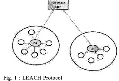
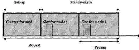
In the recent years, many algorithm and protocols about energy-efficient have been proposed. The cluster- based model is better than single-hop or multi-hop model. The cluster-based routing algorithm was proposed by [4] that optimizes the energy efficiency in WSNs. This algorithm known as Low-Energy Adaptive Clustering Hierarchy (LEACH) where the idea of this algorithm is the cluster members elect cluster head to avoid excessive energy consumption [S]. LEACH consists of 2 phases: set-up phase and steady-phase as shows in Fig. 2. In the set-up phase, sensors may elect randomly among themselves a local cluster head with a certain probability. By doing so,
Fig. 1 : LEACH Protocol
[image:1.515.269.467.558.693.2]heads advertise to all sensor nodes in the network that they are the new cluster heads. Once the nodes receive the advertisements, they decide which head they belong to. In the steady-phase, sensors sense and transmit data to the base through their cluster heads. After a certain period spent in the steady-state, the network goes into the set-up phase again and enters another round of selecting cluster heads.
Fig. 2: LEACH Operation 2.1 Cluster Head Selection
When clusters are created, the sensors elects itself as a cluster head with a certain probability [4]. The selection is stochastic and each node determines a random number between 0 and 1. If this number is lower than a threshold T(n), the node becomes a cluster head. T(n) is determined according to the equation
for nodes that have not been cluster head in the last
1/P
rounds, otherwise T,(n) is zero. Here p is the desired percentage of cluster heads and r is the current round. Using this algorithm, each node will be a cluster head exactly once within llp rounds. After llp - 1 rounds,Tl(n) = 1 for all nodes that have not been a cluster head.
When a node has elected itself as a cluster head, it broadcasts an advertisement message telling all nodes that it is a cluster head. This advertisement is done using a Time Division Multiple Access (TDMA). Non-cluster heads use these messages from the cluster heads to choose the cluster they want to belong for this round based on the received signal strength of the advertisement message.
2.2 Schedule Creation
The cluster head receives all the messages from the nodes that would like to join the cluster. Based on the number of nodes in the cluster, the cluster head creates a TDMA schedule telling each node when it can transmit the data. This schedule is broadcasted back to the nodes included in the cluster.
2.3 Data Transmission
Once the clusters are created and the TDMA schedule is fixed, nodes can start to transmit their data. Assuming nodes always have data to send, they send it during their allocated transmission time to the cluster head. This transmission uses the minimal amount of energy based on the received strength of the cluster head advertisement. The radio of each non-cluster head can be turned off until the node's allocated transmission time, thus minimizing energy dissipation. The cluster head node must keep its receiver on to receive all the data from the nodes in the cluster. Once all the data has been received, the cluster head performs optimization functions such as data aggregation or other signal Twcessing functions to compress the data into a single signal. This composite signal, which is a high-energy transmission since the base station is far away, is then sent to the base station. The cluster heads send these data packets using a fixed spreading code with CSMA.
This is the steady-state operation of LEACH networks. After a certain time, which is determined a priori, the next round begins with each node determining if it will become a cluster head for this round and advertising the decision to the rest of nodes as described in the advertisement phase.
2.4 Limitation in LEACH
Even though LEACH is one of the greatest hierarchical routing algorithms, there were some deficiencies available. The following are deficiencies that available in LEACH:
i. LEACH is not efficient for large-scale networks. ii. Fixed percentage of cluster-heads for any size
network (5%).
iii. The protocol may lead to concentration of cluster-heads in one area of the network.
iv. It assumes that all nodes can communicate over one hop (directly) with the base station.
v. Uniform energy dissipation assumed for both cluster-heads and other nodes in any given round.
vi. All nodes start with equal energy residual levels. Since LEACH has many drawbacks, many researches have been done to make this protocol performs better.
3. Related work
3.1 E-LEACH
[image:2.553.50.273.182.263.2]Proceeding of National Conference of Electric and Electronic Engineering 2012
node has the same probability to turn into CH, that mean nodes are randomly selected as CHs, in the next rounds, the residual energy of each node is different after one round communication and taken into account for the selection of the CHs. That mean nodes have more energy will become a CHs rather than nodes with less energy.
3.2 TL-LEACH
A new version of LEACH called Two-level Leach was proposed by [7]. In this protocol; CH collects data from other cluster members as original LEACH, but rather than transfer data to the BS directly, it uses one of the CHs that lies between the CH and the BS as a relay station. Compare to the LEACH protocol, the CH collects and aggregates data from sensors in its own cluster and passes the information to the Base Station (BS) directly. CH might be located far away from the BS, so it uses most of its energy for transmitting and because it is always on it will die faster than other nodes.
3.3 C-LEACH
Centralized LEACH (C-LEACH) was proposed by [4]. C-LEACH uses a centralized clustering algorithm and the same steady-state phase as LEACH. LEACH-C protocol can produce better performance by dispersing the cluster heads throughout the network. During the set- up phase of LEACH-C, each node sends information about its current location (possibly determined using a GPS receiver) and residual energy level to the sink. In addition to determining good clusters, the sink needs to ensure that the energy load is evenly distributed among all the nodes. To do this, sink computes the average node energy, and determines which nodes have energy below this average.
Once the cluster heads and associated clusters are found, the sink broadcasts a message that obtains the cluster head ID for each node. If a cluster head ID nlatches its own ID, the node is a cluster head; otherwise the node determines its TDMA slot for data transmission and goes sleep until it's time to transmit data. The steady- state phase of LEACH-C is identical to that of the LEACH protocol.
3.4 V-LEACH
This LEACH modification was proposed by [lo]. In V-LEACH, the cluster contains; CH (responsible only for sending data that is received from the cluster members to the BS), vice-CH (the node that will become a CH of the cluster in case of CH dies), cluster nodes (gathering data from environment and send it to the CH).
In the original leach, the CH is always on receiving data from cluster members, aggregate these data and then send it to the BS that might be located far away from it. The CH will die earlier than the other nodes in
the cluster because of its operation of receiving, sending and overhearing. When the CH die, the cluster will become useless because the data gathered by cluster nodes will never reach the base station.
In V-LEACH protocol, besides having a CH in the cluster, there is a vice-CH that takes the role of the CH when the CH dies because the reasons we mentioned above. By doing this, cluster nodes data will always reach the BS; no need to elect a new CH each time the CH dies. This will extend the overall network life time.
4. Modified Leach Description
4.1 Overview
The modified LEACH in this paper taking into account all the limitation that has been listed above. A general network layout is constructed at the base-station by determining the neighbours of all the nodes in the first round. Along with this list the residual energy of each node as well as distance from base-station too is stored which is then used to determine CH at the start of every round. Though this may seem to be rather expensive for the nodes, this procedure is carried out only once i.e. during the initialization of the network and all subsequent rounds require aggregation of the node residual energies only. The node-linkage table for an m-sized sensor network is therefore an 'm x m' bit-field matrix where 1 denotes presence of a link and 0 otherwise. As the matrix is symmetric this can further be halved for memory considerations. The cluster-heads for the subsequent round are selected based on the weightages assigned to the parameters: number of neighbours, residual energy and distance to BS. A sorting of the table reduces the search from an 0 (n2) order to 0 (n). The sort is performed on the basis of residual energy (ranges) and then on the number of neighbours in each range. After selection of CH with elimination of common neighbour nodes to prevent closeness a back track of the now hopefuls is done so that an equal distribution of nodes is assigned to each CH. This ensures uniform node population below each CH.
In LEACH, the number of CH selected in each round is dynamic as opposed to the static methodology. Each round ends when 50% or more of the cluster-heads reach a pre-determined threshold energy value. This is followed by the cluster-heads informing the BS of the status of the current residual energy of all the nodes which it is currently supervising. The selection of cluster- head is then carried out as before.
4.2 Modified LEACH
The processes of Modified LEACH are elaborated as follows:
Initialization:
BS sends out an initial signal along with the TX range to use for finding neighbours.
Flooding:
Each node determines the neighbours in the specified TX range and sends this list back to the base station along with current residual energy along with distance.
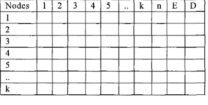
Table creation (BS):
The base station then compiles the data into a table as shown above of neighbours, number of neighbours (n), residual energy (E) and distance (D).
Selection of Cluster-heads:
The cluster heads are selected depending on D, E, n. Max weightage is given to E and appropriate levels to D and n (mathematical model of which is to be constructed for finding the optimum weightages).
Bit-fields are created for the neighbour representation with a 1 indicating the presence of a neighbour and 0 otherwise.
Sorting:
The cluster heads are selected sequentially depending on the sorted list. The list is updated for neighbours based on already selected cluster heads. The process continues until all the nodes have a cluster head. The "cluster-head" assignment to the rest of the nodes is done in a sequential fashion from the top of the stack of cluster heads selected. Each node is then checked against the selected cluster head list to find the nearest cluster head. If the nearest cluster head is in its transmission range then the node is assigned to that cluster for the current round. Round proceeds as in LEACH.
Fig. 2: nED Table for k nodes
5.
Simulation And Result
This section compares the performance of proposed algorithm with LEACH protocol. The performance evaluation includes two parts: First Node Dead (FND) and Half Node Dead (HND). The nodes are simulated to deploy over a square sized area of lOOOm x lOOOm with variable communication range. The different number of nodes (100, 125, 150, 200, 250 and 300)
deploy in a covered area randomly. The simulation was then run for 200 rounds with end criteria of either the number of rounds being completed or at least half the population of sensor nodes are dead.
The scalar quantities such as the round when the first node dies, the round in which at least half the nodes die then recorded for further analysis.
For LEACH algorithm, the FND occur in round 23 (for node = 300) compare to Modified LEACH, where the FND occur in round 98. With 100 nodes, there was no improvement for the FND. As the nodes increase, the round for FND occur in LEACH is decrease while for Modified LEACH, the round for FND to occur is not giving a lot of change. This shows a slight improvement for the network lifetime when the number of node increase.
From Fig. 5, the Half Node Dead (HND) occurs for LEACH and Modified LEACH is not giving a lot of change. Although the number of nodes increases, the difference between LEACH and Modified LEACH does not differ greatly.
---
Merent of Fl& Node Dead for LEC\CH and Modified W H
1B - "
- "
-
" " A AFig. 4: The Number of Rounds when First Node Dead with Different Number of Nodes
Fig. 5: The Number of Rounds when Half Node Dead with Different Number of Nodes
6.
Conclusion
[image:4.541.280.517.336.481.2] [image:4.541.280.517.340.640.2] [image:4.541.280.518.502.652.2] [image:4.541.36.250.510.618.2]Proceeding of National Conference of Electric and Electronic Engineering 2012
some improvements that need to be done for this [lo] Yassein, M. B., Al-zou'bi, A., Khamayseh, Y., & algorithm can perform better and these improvements are Mardini, W. (2009). Improvement on LEACH being implemented. Hopefully after further improvement, Protocol of Wireless Sensor Network (VLEACH). this algorithm will show better result compare to JDCTA: International Journal of Digital Content
LEACH. Technology and its Applications, Vol. 3, No. 2, 132
-
136.
References
[l] Ali, Q. I., Abdulmaowjod, A,, & Mohammed, H. M. (201 1). Simulation and Performance Study of Wireless Sensor Network(WSN) Using Matlab. Iraq J. Electrical and Electronic Engineering Vol. 7 No. 2, 112-119.
[2] Dietrich, I., & Dressler, F. (January 2009). On the Lifetime of Wireless Sensor Network. ACM Transaction on Sensor Network Vol. 5,No. 1, 1-38. [3] Heinzelman, W. R., Chandrakasan, A,, &
Balakrishnan, H. (2000). Energy-Efficient Communication Protocol for Wireless Microsensor Networks. Proceedings of the 33rd Hawaii International Conference on System Sciences (pp. 1-
10). Hawaii: IEEE Explore.
[4] Heinzelman, W., Chandrakasan, A,, & Balakrishnan, H. (2002). An application-specific protocol architecture for wireless microsensor networks. Wireless Communications, IEEE Transactions on , vol.1, no.4 (pp. 660-670). IEEE Explore.
[5] Lewis, F. (2004). Wireless Sensor Network. Smart
Environments: Tecnologies, Protocols and Application. New York.
[6] Liu, Y., Xiong, N., Zhao, Y., Vasikalos, A., Gao, J.,
& Jia, Y. (2010). Multi-Layer Clustering Routing
Algorithm for Wireless Vehicular Sensor Network.
IET Communication Vol. 4, Iss. 7, 810-816.
[7] Loscri, V., Morabito, G., & Marano, S. (2005). A two-levels hierarchy for low-energy adaptive clustering hierarchy (TL-LEACH). Vehicular Technology Conference, 2005. VTC-2005-Fall. 2005 IEEE 62nd (pp. 1809- 1813). IEEE Explore. [8] Tao, L., Qing-Xin, Z., & Luqiao, Z. (2010). An
Improvement for LEACH Algorithm in Wireless Sensor Network. 2010 5th IEEE Confirence on Industrial Electronics and Application (pp. 18 1 1
-
1814). IEEE Explore.
[9] Xiangning, F., & Yulin, S. (2007). Improvement on LEACH Protocol of Wireless Sensor Network.