Response of Soil – Foundation – Structure
Interaction of Tall Building (Frame - Wall)
Structural System under Seismic Effect
Omar Shareef Sadq Qaftan
A thesis submitted in fulfilment of the requirement for the degree of Doctor of Philosophy
School of Computing, Science & Engineering University of Salford
II
CERTIFICATE OF AUTHORSHIP/ORIGINALITY
I certify that the work in this thesis has not previously been submitted for a degree nor has it been submitted as part of requirements for a degree except as fully acknowledged within the text.
I also certify that the thesis has been written by me. Any help that I have received in my research work and the preparation of the thesis itself has been acknowledged. In addition, I certify that all information sources and literature used are indicated in the thesis.
Omar Shareef Sadq Qaftan
III The unavailability of standards or validated analysis techniques of estimating the soil -foundation-structure interaction (SFSI) lead to either simplifying or ignoring this interaction. The structural and geotechnical engineers consider the foundation effect on the multi-story building design. Where both the structural and geotechnical analysis is usually conducted individually. The geotechnical engineer may simplify a multi-degree of freedom to a single multi-degree of freedom oscillator, and on the other hand, structural engineers may ignore the soil-foundation-structure interaction SFSI or represent the nonlinear soil-foundation-Structure interaction with simple linear springs, where the nonlinear Interaction between the superstructure and the substructure is neglected. This study was carried out using experimental and numerical approaches to analysis the Interaction of soil foundation structures under seismic effect.
Experimental work was performed through a series of shaking table test events for different parametric studies such as building height, soil density, and foundation type under the impact of shaking waves representing the soil vibration of seismic effect. Numerical simulation was performed using two popular software packages i.e. ABAQUS and ETABS package to solve the three-dimensional problem of soil foundation structure response under seismic effect. The results obtained from the software will then be compared with those obtained by experimental work.
Based on the literature review, the following parameters (which are believed to have an influence on the Soil Structural Interaction response) were investigated in this study:
• Building characteristics such as the height and mass,
• Soil properties including the dynamic stiffness, damping ratio, shear, angle of internal friction and shear wave velocity,
• Pile group configuration and the nonlinear interaction between piles and the Soil,
IV parameters on the structure and compare the outcome of those tests with the predictions from the software programme to validate the numerical model for further dynamic studies.
The experimental work was divided into four stages: Firstly, the fixed base stage. Secondly, the soil container stage. Thirdly, the soil-foundation-structure interaction (raft foundation). Fourthly, the soil-foundation-structure interaction (pile foundation). Comparing the results of the numerical model and the experimental measurements, it can be concluded that the employed numerical model is appropriate for the simulation of the soil-foundation - structure interaction under dynamic effect. The scale models demonstrate some behaviour of the prototype in economical way without examining the prototype itself. Consequently, the proposed numerical model of raft foundation and pile foundation are valid and qualified method of simulation with sufficient accuracy which can be employed for further numerical dynamic soil-structure interaction investigations.
V
ACKNOWLEDGMENT
This PhD Research work could not have done without the understanding, guidance, assistance, and review by numerous people throughout the project.
The author would like to express his gratitude and appreciation and to his supervisors, Dr. Tahsin Toma-Sabbagh and Dr. Laurence Weekes, for their limitless support, tireless contributions, and guidance throughout this work.
Warm thanks to my friends and colleagues for sharing their time and friendship with the author and rendered precious help. The author also feels a deep sense of gratitude to all the academic and non-academic staff in the school of civil for the help rendered. Words are not enough to thank my family, my wife, my son, my daughters, my brothers and sister for the support they have given me during this long and sometimes difficult journey.
The author would very much like to express his love and gratitude to his mother and father for their love and support, and for instilling in me the value of learning and providing me outstanding opportunities to do so throughout my life.
VI
LIST OF PUBLICATIONS
• Qaftan, O.S. and Sabbagh, T.T., 2017. Experimental Simulation of Soil Boundary Condition for Dynamic Studies. World Academy of Science, Engineering and Technology, International Journal of Environmental, Chemical, Ecological, Geological and Geophysical Engineering, 11(9), pp.789-796, Paris, France June 2017.
https://waset.org/Publication/experimental-simulation-of-soil-boundary-condition-for-dynamic-studies-/10007890
• Qaftan, O., Weekes, L., Toma-Sabbagh, T.M. and Augusthus Nelson, L., 2018, March. Experimental & numerical simulation of soil boundary conditions under dynamic effects. In Proceedings, 16th European Conference on Earthquake Engineering, Thessaloniki, Greece, June 2018.
http://usir.salford.ac.uk/46831/
• Experimental and numerical simulation of scaled model of tall multi-storey wall-frame system for seismic studies (under review)
• Soil-foundation-structure interactions of a multi-storey wall-frame structural system under seismic loading conditions (under review)
• Evolution and simplification of different parmeters on the response of soil foundation structure interaction (under review).
VII
CONTENTS
1 CHAPTER ONE - INTRODUCTION ... 1
General ... 1
Soil-foundation-structural interaction statement & contribution to knowledge ... 2
Aims and Objectives ... 4
1.3.1 Literature Review... 5
1.3.2 Experimental work ... 5
1.3.3 Numerical work ... 5
The thesis layout... 6
2 CHAPTER TWO - LITERATURE REVIEW ... 8
General ... 8
Multi-storey buildings under seismic forces ... 9
Background of Structure dynamic behaviour... 11
Dynamic Behaviour of Soil ... 14
Dynamic behaviour of Foundation ... 17
2.5.1 Embedded raft foundation... 17
2.5.2 Pile foundation ... 18
Concept of Soil-Foundation-Structure Interaction (SFSI) ... 19
Available modelling methods for soil-foundation-structure Interaction ... 23
Free Field Ground Motion... 26
Simulation of Soil Boundary Condition for Soil Container ... 29
Building code recommendation for Soil Foundation structure Interaction (SFSI) ... 30
Soil-Foundation-Structure Interaction (SFSI) ... 33
2.11.1 Soil Structure Interaction under Seismic effect (Theoretical Studies) ... 33
Soil-structure interaction under sismic effects (expermental studies) ... 38
Summary ... 49
3 CHAPTER THREE - EXPERIMENTAL WORK ... 50
General ... 50
Experimental work methodology ... 50
Prototype Characteristics... 52
Scaling Factors for Shaking Table Tests ... 54
VIII
3.6.1 Scaled Model ... 60
3.6.2 Soil Container Design ... 62
3.6.3 Soil Properties and placement ... 64
3.6.4 Foundations Models ... 67
3.6.5 Accelerogram generation ... 68
3.6.6 Shaking table tests experiments ... 69
3.6.7 Shaking Table Tests on Model Structure supported by Raft Foundation ... 81
3.6.8 Shaking Table Tests on Model Structure supported by Raft on Pile Foundation 84 Summary and Conclusions ... 86
3.7.1 The shaking table tests of the soil container (stage 2) ... 87
3.7.2 The shaking table tests of the soil foundation structure interaction (stage 3 & stage 4) 87 4 CHAPTER FOUR - NUMERICAL WORK ... 89
General ... 89
Finite element analysis ... 92
4.2.1 Time History Analysis ... 92
4.2.2 Response spectrum analysis ... 95
Three-dimensional finite element software (ABAQUS) ... 97
Elements in ABAQUS ... 98
4.4.1 Solid element: ... 99
4.4.2 Beam element... 100
4.4.3 Shell element ... 100
Soil boundary condition ... 101
Three-dimensional models of soil-structure system ... 104
Pre-processing ... 108
Fixed-base response model ... 111
Soil-structure interaction models ... 112
Summary ... 113
5 CHAPTER FIVE - VERIFICATION OF THE DEVELOPED 3D NUMERICAL MODEL ... 114
General ... 114
Prototype & Scaled model Design ... 114
IX
5.4.1 Structure and foundation ... 119
5.4.2 Soil container and soil materials ... 119
5.4.3 Interactions and boundary conditions ... 120
5.4.4 Time-History Analysis ... 120
Test program/ results and discussion ... 121
5.5.1 Fixed Base Scaled Model... 121
5.5.2 Soil Container ... 124
5.5.3 Structure Supported by Raft Foundation ... 128
5.5.4 Structure Supported by Raft on Pile Foundation ... 130
Summary ... 131
6 CHAPTER SIX - EVOLUTION AND SIMPLIFICATION OF DIFFERENT PARAMETERS ON THE RESPONSE OF SOIL- FOUNDATION-STRUCTURE INTERACTION ... 133
General ... 133
Evolution and simplification work methodology ... 134
Nonlinear Time-History Dynamic Analysis ... 135
Geometric Non-linearity and P-Delta Effects in Time-History Analysis ... 135
Utilised Ground Motions in Time-History Analyses ... 138
6.1 Characteristics of the Adopted Soil-Foundation-Structure Systems ... 138
Geotechnical Characteristics of Employed Subsoils ... 139
Determining the Seismic Response of Models Considering the Dynamic Soil- Foundation –Structure Interaction ... 140
6.2 Discussion of the Dynamic Structure Response ... 142
6.3 Soil-Foundation-Structure Interactions with Raft Foundation ... 142
6.3.1 Effect of Ground Acceleration (raft foundation) ... 144
6.3.2 Effect of Soil Properties (raft foundation) ... 145
6.3.3 Effect of Structural Properties (Raft Foundation) ... 145
6.4 Soil-Foundation-Structure interactions of pile foundation ... 147
6.4.1 Effect of Soil Properties (raft on pile foundation) ... 149
6.4.2 Effect of structural properties (raft on pile foundation) ... 150
6.4.3 Effect of Ground Motion (raft on pile foundation) ... 151
6.4.4 Effect of pile length and pile number ... 152
The Proposed Simplification method: ... 153
X
Summary ... 162
7 CHAPTER 7 - CONCLUSIONS AND RECOMMENDATION ... 165
General ... 165
Summary ... 166
Recommendations for future work ... 169
8 List of References ... 171
XI
LIST OF FIGURES
Figure 2-1 Building tilted by ground failure caused by soil deformation (Taiwan earthquake,
2018) 9
Figure 2-2 Schematic of seismic force representation(Taranath, 2009) 10
Figure 2-3 Single degree of freedom system 11
Figure 2-4 Undamped free vibrations of a single degree of freedom system (Taranath, 2009;
Clough and Penzien, 2013) 13
Figure 2-5 Damped free vibrations of a single degree of freedom system (Taranath, 2009;
Clough and Penzien, 2013) 13
Figure 2-6 Representation of multi-mass system by a single mass system (Taranath, 2009;
Clough and Penzien, 2013) 13
Figure 2-7 Hysteresis Loop (Tabatabaiefar and Massumi, 2010) 15 Figure 2-8 Stress-strain curve with a variation of shear modulus and modulus reduction
curve (Tabatabaiefar and Massumi, 2010) 16
Figure 2-9 Embedded raft foundation (Stewart, 1999) 18
Figure 2-10 Coupled dynamic model of structure and soil for horizontal and rocking motions
proposed by Zhang and Wolf (1998) 21
Figure 2-11 Equivalent one degree of freedom system presented by Zhang and Wolf (1998) 22 Figure 2-12 Response of the equivalent soil-structure system: (a) maximum structure
demand, (b) maximum total displacement of the structure relative to the free field
ground motion (Wolf and Obernhuber, 1985) 23
Figure 2-13 Winkler foundation model (Bowles, 1996) 24
Figure 2-14 Soil model in lumped parameter methods (Bowles Joseph, 1996) 25 Figure 2-15 Common seismological terms used for evaluation of an earthquake for a given
site b (Chowdhury and Dasgupta (2008) 27
Figure 2-16 Types of seismic waves (Chowdhury and Dasgupta, 2008) 27 Figure 2-17 Comparison of different types of soil container by Moss et al., (2010) 29
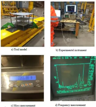
Figure 3-1 Trial scaled structural model 52
Figure 3-2 Details of the prototype 54
Figure 3-2 Lumped mass simplification of multi-story buildings (Serrano et al., 2017) 57
XII
Figure 3-6 Scaled model design 62
Figure 3-7 The soil container design 64
Figure 3-8 Dilatancy of dense sand (Ryan and Polanco, 2008) 65
Figure 3-9 Sieve analysis of selected sand 66
Figure 3-10 Constructed scaled model and foundation types 68
Figure 3-11 Time – acceleration inputs 69
Figure 3-12 Shaking table at Heavy Structure lab, Salford University 70
Figure 3-13 Fixed base shaking table test 71
Figure 3-14 Fixed base experimental outputs 73
Figure 3-15 Soil container fixed on shaking table at Salford University 74
Figure 3-16 Layout of accelerometers 76
Figure 3-17 The effect of the container boundary of the soil response 77 Figure 3-18 (a) The evolution of Shear modules G with shear strain γ (b) The evolution of
damping Ratio D with shear strain γ (Seed et al. 1986) 77
Figure 3-19 The soil response based on acceleration outputs 79 Figure 3-20 Measurement of time-acceleration and time displacement at the table and soil
mass level 80
Figure 3-21 Dynamic properties of selected sand 80
Figure 3-22 Soil foundation structure system details (raft foundation) 82
Figure 3-23 Stage 3 structure supported by raft foundation 83
Figure 3-24 Soil foundation structure system details (raft on pile foundation) 85 Figure 3-25 Stage 4 Structure supported by raft on pile foundation 86 Figure 4-1 Shear deformation of multi-storey buildings under seismic force (Han and Cathro,
1997) 91
Figure 4-2 Newton-Raphson iterations used in nonlinear analysis (number of iterations, 𝒌 =3) 93
Figure 4-3 ABAQUS elements (ABAQUS documentation, 2013) 98
Figure 4-4 hexahedral C3D8R elements with integration point scheme (ABAQUS
Documentation, 2013) 99
XIII condition, b) dashpot boundary condition c) flexible plate element boundary condition
103
Figure 4-8 Numerical elements modelled by ABAQUS 105
Figure 4-9 Mohr-Coulomb model 106
Figure 4-10 Soil element boundary model by ABAQUS software 107
Figure 4-11 Fixed base numerical model by ABAQUS 111
Figure 4-12 So-l foundation-structure interactions model by ABAQUS 112
Figure 5-1 Detail of the prototype and scaled model 116
Figure 5-2 Fixed base model 122
Figure 5-3 Maximum lateral displacement of experimental and numerical outputs 123 Figure 5-4 Soil container experimental and numerical acceleration outputs 125
Figure 5-5 Experimental and numerical spectral outputs 126
Figure 5-6 Structures supported by (a) raft foundation and (b) raft on pile foundation 127 Figure 5-7 Numerical simulation of soil foundation structure interaction (raft foundation) 128
Figure 5-8 Structure on raft foundation output 129
Figure 5-9 Numerical simulation of soil foundation structure interaction (raft on pile
foundation) 130
Figure 5-10 Structure on raft on pile foundation output 131
Figure 6-1 Configuration of P-∆ effect 137
Figure 6-2 Structures supported by (a) raft foundation and (b) raft-on-pile foundation 141 Figure 6-3 Numerical model for soil-foundation-structure interactions (raft foundation) 143 Figure 6-4 Effect of acceleration intensity on the maximum displacement (raft foundation)
144 Figure 6-5 Effect of soil properties on maximum displacement (raft foundation) 145 Figure 6-6 Effect of structure height on maximum displacement (raft foundation) 146 Figure 6-7 Soil-foundation-structure interaction (raft-on-pile foundation) 148 Figure 6-8 Effects of soil properties on maximum displacement (raft-on-pile foundation) 149 Figure 6-9 Effect of structure height on the pile foundation 150 Figure 6-10 Effect of ground motion on maximum displacements (pile foundation) 151 Figure 6-11 Effect of pile length on maximum displacements 152 Figure 6-12 Effect of number of piles on maximum displacements 153
XIV Figure 6-15 Soil-foundation-structure interaction moment of structure supported by
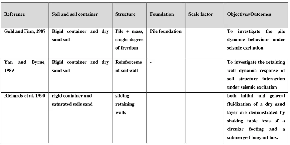
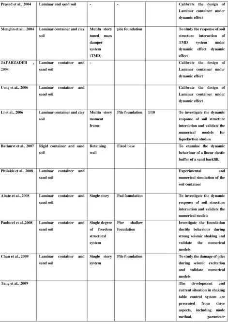
XV Table 2-1 Summary of available previous shaking table experiments 43
Table 3-1: Shaking Table Specifications 51
Table 3-2 Scaling relations for geometric scaling factor (λ), (Moncarz and Krawinkler, 1981) 56 Table 3-3 The required characteristics of the scaled structural model parameters 61
Table 3-4 Selected sand properties 66
Table 3-5 Characteristics of model piles 67
Table 3-6 Fixed base shaking table test schedule 72
Table 3-7 Experimental Soil Container Tests 75
Table 3-8 Stage 3 structure supported by raft foundation experiments schedule 81 Table 3-9 Stage 4 structure supported by raft-on-pile foundation experiments schedule 84
4-1 Soil properties defined in ABAQUS Software 106
Table 5-1 Summary of porotype and scaled model characteristics 117
Table 5-2 Soil properties adopted in the numerical models 118
Table 5-3 Characteristics of pile 119
Table 6-1 Sand soil adopted for parametric study 140
Table 6-2 Scaled structural properties 140
Table 6-3 Structure supported by raft foundation parametric study 142 Table 6-4 Structure supported by raft-on-pile foundation parametric study 147
Table 6-5 Soil factor (T) analysis output 155
Table 6-6 Scaled structural properties 156
Table 6-7 Relationship factors for the prototype and scaled models 159
Table 6-8 Summery of structure on raft parameter study 160
XVI
A area
Aloop area of the hysteresis loop
a foundation width
C cohesion
c damping coefficient of the structure
[C] damping matrix
ch horizontal damping coefficient of the subsoil
cθ rocking damping coefficient of the subsoil
𝑐𝑥
Cs seismic design coefficient of the fixed-based structure
Cu coefficient of uniformity
∆ Corresponding displacement
D damping Ratio
SD Structure displacement
e actual void ratio
𝑒𝑚𝑖𝑛 minimum void ratio
𝑒𝑚𝑎𝑥 maximum void ratio
E modulus of elasticity (Young modulus)
Es soil subgrade reaction
F force
f natural frequency of fixed base structure
f ˜ natural frequency of soil-structure system
fck specified compressive strength
𝑓𝑚 natural frequency of the model
𝑓𝑝 natural frequency of the prototype
G shear modulus of the soil
G0 shear modulus of the soil at small strains
Gmax largest value of the shear modulus
Gsec secant shear modulus
Gtan tangent shear modulus
XVII
h height of the structure
ℎ𝛳
lateral displacement at the top of the structure due to rotation of the base
I moment of inertia
Ic flexural rigidity of the building columns
i step
i+1 step increment
K stiffness of the structure
ks shear spring stiffness
kn normal spring stiffness
𝑘𝑥 stiffness in x direction [K] stiffness matrix
m mass of the structure
[M] mass matrix
ρ soil density
𝑝𝑚 scaled model density
𝑝𝑝 Prototype density
Riext external force
𝑅𝑖𝑖𝑛𝑡 internal force
T soil factor
T the natural period of the fixed-base structure
τ, 𝜏𝑐, 𝜏′𝑧𝑦 shear stress
u lateral displacement at the top of the structure due to structural distortion
ug, horizontal seismic excitation
𝑢̃𝑔 effective input motion
ü acceleration
𝑢̇ velocity
υ Poisson’s ratio
vs Shear velocity
𝜔̃ effective frequency
ω0 the natural frequency of the fixed base structure
XVIII
ζ the equivalent viscous damping ratio
𝜁̃̃ effective damping ratio
Γ𝑛 Maimum displacment
λ geometric scaling factor
σy yield stress
ɸ friction angle
𝛾𝑐, ɣ𝑧𝑦 shear strain
∝ damping control
β, γ damping parameter
r radius
γ density
ɣ𝑚𝑎𝑥 maximum density
XIX SFSI soil foundation structure interaction
MDOF multi degree of freedom SDOF single degree of freedom
3D three dimensions
FDM finite difference method FEM finite element method
RC reinforcement concrete SSI Soil structure interaction
FIM Foundation input motion
1
1
CHAPTER ONE - INTRODUCTION
General
Earthquake excitations may affect many multistory structures. Damages may occur due to structural faults and resonance effects or soil conditions. The particular failure can vary depending on the structural system and support, including foundations types and the soil conditions. Under the seismic effects, structures and the soil underneath are subject to seismic ground motion. This motion transfers as a motion acceleration to each part of the construction system. Construction mass and motion acceleration cause vibration within the structure and lead to partial damage or collapse of the whole structure. Numerous multistory buildings have been built in earthquake zone areas with different types of foundations. In the foundation design of the multi-storey buildings, several options are available such as shallow foundation and pile foundation. The design engineers select the appropriate foundation type to carry both gravity and earthquake loads. However, various foundations behave differently during an earthquake (Yegian et al., 2001). The response of structures under seismic effects has therefore been a major concern for design engineers around the world.
The seismic response of structures is usually determined by assuming fixed support at the structure base. This approach is acceptable when the structure is constructed on solid rock, whereas two considerations are needed when determining the seismic effects on the structures based on soft soils. Firstly, the forces on the structure originating from the free-field motion, which are generated by the response of the structure’s body and the base system. Secondly, further deformations accrued within the structure as a result of the dynamic behaviour of the soil underneath. The assumption of soil influences on the structure movement and reaction of the structure influences to the soil response is referred to as the soil-structure-interaction (Kramer, 1996).
2 parameters that have an impact on the structure response to seismic effects such as, structure geometry, foundation types, characteristics of soil etc. When the ground motion shakes the building base, the building will swing back and forth causing differential displacements and resulting in loads transferring to the underneath and surrounding soil through the foundation which is typically a raft or pile (Bowles, 1997).
Soil-foundation-structural interaction statement & contribution to
knowledge
The unavailability of standards or validated analysis techniques for estimating the soil-foundation-structure interaction (SFSI) leads to either ignoring or simplifying this interaction. The structural and geotechnical analysis is usually conducted individually. The geotechnical engineer may simplify a multi-degree of freedom to a single degree of freedom oscillator. Moreover, the structural engineers may ignore the SFSI or use simple linear springs to represent the nonlinear SFSI and neglect the nonlinear interaction between the superstructure and the substructure (Hokmabadi et al., 2013).
During earthquake excitations, the building or structure interacts with the surrounding soil. The dynamic behaviour of structure and soil should be studied at the same time when dynamic loads in a particular time act on superstructure and surrounding soil. It has been established that structures can be designed carefully and constructed safely against several seismic performance criteria to prevent collapse during earthquakes. The nature of foundation, structural system and the ground motion duration and characteristics are the primary functions of structure response (Deepa and Nandakumar, 2008).
3 represented directly with a constant value of stiffness and damping during the design procedure. Therefore, in the seismic design of the buildings more research on soil is required considering the influence of SFSI with a rigorous accounting of the higher modes of response and different foundation types (Yegian, Mullen and Mylonakis, 2001).
The main advantage of an experimental simulation model in geotechnical engineering under controlled conditions is to provide the opportunity for better understanding of SFSI. Moreover, it is used as a reference for numerical and empirical analysis. Shaking table tests for the multistory structures are highly in demand, where the dynamic properties of the prototype structures such as natural frequency and the number of simulated stories are required. Moreover, conducting a complete set of experimental tests in this study with different foundation types namely, raft foundation, and raft on pile foundation leads to experimentally comparable results. These results are used to determine the influence of SFSI on the superstructure supported by different types of foundations under the seismic load (Tabatabaiefar and Massumi, 2010).
4 Due to the limitations of Winkler methods, the researchers utilised advanced analytical tools to perform fully-nonlinear mathematical models to study the seismic effects on the pile foundations. However, the adopted numerical models need to be verified against the experimental measurements before utilising them as a tool for nonlinear time-history of soil-foundation-structure interaction analysis. Therefore, efforts are required to develop a verified numerical modelling procedure to be capable of considering the significant aspects of SFSI analysis. Thus, this model can be used for further investigation of the influence of SFSI on the seismic response of buildings.
Aims and Objectives
This study aims to look into the influence of the foundation type and soil on the response of the regular multistory dual structural systems (frame-wall structural system) under seismic effects and to examine the structure analysis for safe, and reliable design.
5 Following the introduction, a comprehensive survey of the literature associated with the seismic soil-foundation-structure interaction (SFSI) is presented in Chapter 2. The dynamic behaviour of soils, the modelling techniques to simulate the impact of soil-foundation-structure interaction (SFSI) on the behaviour of structure, and the available building codes for seismic soil-structure interaction are presented. Furthermore, previous experimental investigations of (SFSI) are reviewed and discussed.
1.3.2 Experimental work
This part of the study comprises the following activities:
• Simulating the complex of a 3D non-linear scale structural model for experimental shaking table tests.
• Verification and calibration of the soil-foundation- structure model components for shaking table tests including structural models, foundations types, soil mix, and a soil container.
• Preparing and testing the dynamic properties of soil and container.
• Treating the dynamic soil behaviour, foundation, structure, and investigating the soil-structure interaction with seismic effects as accurately as possible. • Conducting a series of planned experimental shaking table tests.
1.3.3 Numerical work
• Development of an enhanced nonlinear three-dimensional soil-foundation-structure model.
• Direct determination of story drifts by employing a multi-degree of freedom (MDOF) under seismic effect.
• Detailed study of the response of the regular multistory dual structural system supported by different types of foundations to the seismic events.
6 • Acquiring a better understanding of the fundamental parameters that affect the soil- foundation–structure interaction under seismic loads of superstructure regarding shear distribution, the rocking of the superstructure, lateral deformations and foundation depths.
• Studying and comparing the effects of the foundation type on the superstructure’s seismic response about shear distribution, the rocking of structure, lateral deformations, foundation depths, and height of the structure. • Proposing a simplified design procedure to enable structural engineers to
determine the soil structure interactions for regular multi-storey (wall columns) structural system building frames utilising fixed base analysis as well as other site conditions and structural characteristics.
The thesis layout
Chapter 1 outlines an introduction to the aims and objectives and the organisation of the thesis. Chapter 2 presents a literature survey on the soil foundation structure interaction under seismic effects. The dynamic behaviour of structures was investigated, the available modelling techniques for (SFSI) simulation were discussed, and the available seismic building codes related to soil- foundation structure interaction were summarised. Furthermore, previous numerical and experimental investigations of (SFSI) are reviewed and discussed.
Chapter 3 illustrates the modelling procedure, the scaling methodology and the scaling factors utilised in the simulation of the soil container and superstructure. Furthermore, instrumentation setup and the soil container test preparation and experimental structural models are described. The proposed numerical model for soil foundation structure was verified using the laboratory shaking table tests. Finally, the influence of different foundations, structure height and soil types on the response of the superstructure were investigated.
7 boundary conditions, and the dynamic loading were described.
Chapter 5 illustrates the validation of all stages of experimental shaking tests and investigates the capabilities of the numerical model in simulating soil foundation structure models. The results of the shaking table tests (reported in Chapter 3) are employed to verify and calibrate the numerical model by ABAQUS software. Accordingly, the scaled model of two basements plus fifteen-storey structure is simulated for different types of foundations, and the results are compared with the experimental measurements.
8
2
CHAPTER TWO - LITERATURE REVIEW
General
Geotechnical Engineering is an essential part of the earthquake engineering. Soil-foundation-structure-interaction is a complicated subject required to be analysed and examined by several experimental and numerical models. For twenty years ago, the soil-foundation-structure interaction analysis has been utilised in practice as follows. Structural engineers used to design their frames considering the structure as a fixed base. On consummation of the study, they supply the moment, shear, and reaction applied at the pedestal of the structure to the foundation design engineer to do foundation design. On the other hand, soil mechanics specialists conduct a ground investigation at the construction site studying different soil parameters. Based on various lab and field investigations, the allowable bearing capacity value of the ground is calculated. This becomes the bearing capacity input value which is utilised by the foundation design engineer. The foundation engineers used to review the soil report, find out the bearing capacity of the soil underneath, and study the recommendations of the geotechnical investigation report to obtain the nature of foundation.
9 Figure 2-1 Building tilted by ground failure caused by soil deformation (Taiwan
earthquake, 2018)
Multi-storey buildings under seismic forces
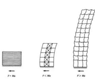
10 mass pushes a member down to move or bent out by the lateral forces. This effect is the so-called p-∆ effect. In earthquakes, mostly the vertical load causes the collapse of buildings and very rarely the buildings fall over. The ground motions and motion duration are the major concern in structure design under seismic effects. In general, tall structures have a different response to ground motion compared to low-rise structures. The inertia forces depend on the ground acceleration, building mass, and the structure’s dynamic characteristics (Figure 2-2). If a structure and its foundation are constructed on stiff ground, the inertia force F can be determined by Newton’s law F = Ma, Where
[image:29.595.132.454.319.585.2]M is the structure mass, and ‘a’ is the acceleration.
Figure 2-2 Schematic of seismic force representation(Taranath, 2009)
11 structural system and materials used in the construction. Within the few seconds of an earthquake starting, the ground acceleration increases up to a peak value (Stafford and Coull, 1991) (Li at el, 2002; Taranath, 2009; Clough and Penzien, 2013).
Background of Structure dynamic behaviour
For buildings with uniform stiffness and mass distribution, dynamic analyses are used to investigate the structural characteristics such as vertical distribution of lateral forces, dynamic loads resulting from torsional motions and the influence of higher modes. The available dynamic codes analysis is dependent on the static methods in which the simplified procedures proposed by single-mode response and corrections of the higher mode effects are used. This method is suitable for buildings with regular structure systems.
Dynamic analysis methods are suitable for design of buildings with irregular or unusual structural systems which have elastic response spectrum analysis and time-history analysis. The response spectrum analysis is more simple than the time-history analysis procedure. Time-history is incorporating time effects in determining the dynamic structure response. The structures response can be represented as either a simple or a complex oscillator under the ground motions excitation. The simple oscillator can be represented by a floor mass with two supporting columns and a single degree of freedom system (SDOF) (Figure 2-3), while the complex oscillator is represented by the multi-mass system with a multi degree of freedom (MDOF) system (Taranath, 2009).
12 The floor mass M is the resultant of dividing the floor weight W of the system by the gravity acceleration g, (M = W/g). The system stiffness K is determined by dividing the applied force F by the corresponding displacement ∆. If the structure is subjected to external force and then released suddenly, the structure vibrates at a specific frequency representing the time for one complete cycle of mass movement. The relationship 2.1 gives the period T (Taranath, 2009):
T = 2π√𝑀
𝐾 2.1
The system vibrates forever in the absence of damping (Figure 2-4). In an actual structural system, the structure has a damping value depending on the structural properties. The amplitude of motion is gradually decreased until the structure stops completely as shown in (Figure 2-5).
13 Figure 2-4 Undamped free vibrations of a single degree of freedom system
(Taranath, 2009; Clough and Penzien, 2013)
Figure 2-5 Damped free vibrations of a single degree of freedom system
(Taranath, 2009; Clough and Penzien, 2013)
.
Figure 2-6 Representation of multi-mass system by a single mass system
14 For most multi-storey structures, the nonlinear response can occur during seismic excitations, making the nonlinear analysis more suitable for building design. Despite the availability of nonlinear analysis programs often they are not used in the design practice because of complicated results which are hard to be interpreted and applied to the design criteria. Instead, based on linear elastic procedures the response spectra are used (Fan et al, 2009), (Stafford Smith at el, 1991), (Li at el, 2002), (Taranath, 2009), (Clough and Penzien, 2013).
Dynamic Behaviour of Soil
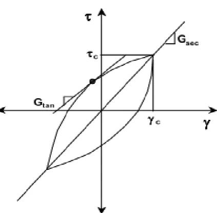
The soil response to dynamic loads is associated with the mechanical soil properties. In this section, the seismic problem of the multi-storey buildings is considered. The mechanical properties are shear wave shear modulus (G), Poisson’s ratio (ν), velocity (𝑣𝑠), and the damping ratio (D). The specific expression “dynamic soil properties” is used in many non-dynamic type problems. The low strain levels of soil mass are inducted under wave propagation. However, soils subjected to seismic effects may result in stability problems as considerable strain is induced. (Figure 2-7) shows the hysteresis behaviour of soil under the dynamic load. The hysteresis response of soil can be estimated by considering two important parameters of hysteresis loop shape (Kramer, 1996a). The loop inclination represents the stiffness and the tangent shear modulus varies with the dynamic force. However, the average value of the loop may be estimated by the secant shear modulus (𝐺𝑠𝑒𝑐).
𝐺
𝑠𝑒𝑐=
𝜏𝑐𝛾𝑐
2.2 Where
𝛾
𝑐is
the shear strain𝜏
𝑐 is the shear stress.15 The damping ratio is represented by the area of the hysteresis loop for the energy dissipation as follows:
ζ =
12𝜋 𝐴𝑙𝑜𝑜𝑝 𝐺𝑠𝑒𝑐𝛾𝑐2
𝜏𝑐
𝛾𝑐
2.3
[image:34.595.189.401.227.434.2]
Figure 2-7 Hysteresis Loop (Tabatabaiefar and Massumi, 2010)
16 and over damped, respectively. In earthquake engineering, most problems are within the underdamped limits which are affected by the soil stiffness under the seismic effect.
Figure 2-8 Stress-strain curve with a variation of shear modulus and modulus reduction curve (Tabatabaiefar and Massumi, 2010)
The stress strain behaviour of cyclically loaded soil is complicated, and the geotechnical engineers recognise that this behaviour is challenging to simulate accurately using simple models. The simplicity and accuracy of this behaviour depend on many factors in the proposed model. In the methods involving the soil physical model the indication of the low-strain is based on the equivalent linear model approach. This method is simple and commonly used in a dynamic model. However, representation of many soil properties under dynamic force is insufficient.
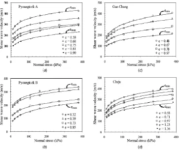
Shear wave velocity (𝑣𝑠) is used as a parameter for characterisation of shallow soil
geophysical models in order to determine the soil shear modulus. The importance of the shear wave velocity is that the particle in motion travels perpendicular to the direction of wave propagation. Furthermore, a shear wave is able to measure the shear properties of the soil skeleton irrespective of fluids because the shear wave flows through the solid particles only, while fluids cannot take shear. Maximum shear modulus (𝐺𝑚𝑎𝑥) is determined by the simple elastic relationship based on the shear
17
𝐺𝑚𝑎𝑥 = ρ ⋅ 𝑣𝑠2 2.4
Where
ρ is the soil mass
and 𝑣𝑠 is the shear velocity.
The dynamic shear modulus is estimated by advanced correlations based on the standard penetration test, Atterberg limits and grain size distributions (Vucetic and Dobry, 1991), (Luna and Jadi, 2000). The shear modulus is used to conduct advanced soil modelling to represent the dynamic response of the soil-foundation-structure system. Shear modulus at low-strain levels is measured by geophysical techniques utilised to measure the parameters of the stiffness matrices which are used as input for finite element analysis of soil foundation model under seismic effect.
Dynamic behaviour of Foundation
The stiffness of foundation elements has an impact on the response to soil-foundation-structure interactions subjected to a dynamic load. The deviation of foundation motions from free-field motions is based on the foundation stiffness. Variable ground motions within the building cause one of these deviations due to the stiffness and strength of the foundation system. Another cause of foundation motions deviation is the embedment effects, in which the level of foundation motions are reduced because of the reduction of ground motion with depth below the level of the free ground surface. For the foundations supported by piles elements, the piles interact with wave propagation at the foundation level.
2.5.1 Embedded raft foundation
18 thickness or half space thickness. Kausel et al. (1978) and Day (1978) described analytical solutions of foundation input motions at the base of the cylinder of embedded foundation as a function of ground motion. Structure rocking is also introduced as a result of differential displacements occurring over their embedded depth level. In (Figure 2-9), D is the footing depth, L is the foundation base diameter, and (𝑣𝑠) is the shear wave velocity.
Figure 2-9 Embedded raft foundation (Stewart, 1999)
Stewart, (1999) reviewed the rigid cylinder model predictions for a structure with embedded base level. They concluded that there is a dynamic significance interaction of soil structure system as a result of embedded base effects. In general, the results illustrate the reduction of ground motions at the foundation level relative to the free field motions.
2.5.2 Pile foundation
19 problem, and well-calibrated engineering models are not available. Berones and Whitman (1982); Barghouthi (1984); Mamoon and Banerjee (1990); Fan et al. (2009), Kaynia and Novak (1992) ; Nikolaou et al. (2001), described the vertical piles and pile groups in elastic soil under dynamic loads. These studies do not incorporate the effects adequately. Kim and Stewart (2003) concluded that there are variations between motions measured at the base level and free-field ground motions. Kim and Stewart (2003) proposed solutions for the interaction problem based on varying flexural rigidity.
Concept of Soil-Foundation-Structure Interaction (SFSI)
The soil-structure interaction concept was developed in early 20th century with advances in SSI analysis methods in the mid-20th century. Kausel (2010) described SSI as the static and dynamic phenomena of a compliant soil and a super-structure. Both the structure and the soil through its foundation develop reaction to the seismic loading due to the dynamic requirements at their interface. This reaction is ultimately changing the structure and soil response, and is known as soil-structure-interaction effect of structure response in comparison with structure supported by fixed base under seismic effect (Wolf, 1985; Mylonakis et al., 2000; Shakib et al., 2004; Pitilakis et al., 2008). The fixed-base structural response is commonly used in the dynamic analysis of conventional building structures. It is recommended that SSI effects must be studied for relatively soft soils or structures with a high aspect ratio (tall building in comparison with its width). The soil structure interaction can be ignored when considering structures founded on very stiff soils or rock (BSI, 2008b).
20 The soil structure system dynamic equation can be written as follows:
[M] {ü} + [C] {u̇} +[K] {u}= -[M] {1} üg+{Fv} 2.5
where,
[M], [C] and [K] are the structure mass, damping, and stiffness matrices, respectively. {ü}, {u̇}and {u}, are the node accelerations, velocities and displacements of the structure which are relative to the underlying soil foundation, respectively.
{üg} is ground acceleration,
and {Fv} is the force vector corresponding to the viscous boundaries.
Zhang and Wolf (1998) indicated that a simple analysis is adequate to demonstrate the significant effects of soil-structure interaction considering the structure as a simple SDOF (single degree of freedom) system characterised by mass (M), stiffness (K), and damping coefficient (c). Furthermore, the soil is assumed rigid at the base considering the soil as a hard deposit. Therefore, the natural frequency by this assumption is a fixed base system, and it only depends on the structure stiffness and mass and can be determined as:
𝝎𝒐 = √𝒌
𝒎 2.6
The equivalent viscous damping ratio (ζ) can be calculated using:
ζ =𝒄𝝎𝒐
𝟐𝒌 2.7
As per Zhang and Wolf (1998) this indicates that the soil structure system is represented by a simple dynamic model. In this system, the foundation can translate and rotate. This system consists of the rigid bar with the horizontal and rocking springs
21 Figure 2-10 Coupled dynamic model of structure and soil for horizontal and
rocking motions proposed by Zhang and Wolf (1998)
In (Figure 2-10), (h) is the height, (k) is the spring stiffness coefficient, (m) is the structure mass, (𝑟𝑜) is the radius of the base.
This system indicates that the main effects of soil-structure interaction for a horizontal excitation are lateral displacement (u) at the top of the structure and the lateral displacement (ℎ𝛳 ) due to the foundation rotation.
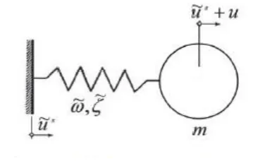
22 Figure 2-11 Equivalent one degree of freedom system presented by Zhang and
Wolf (1998)
Where
𝜔̃ , 𝜁̃̃ and 𝑢̃𝑔 are the effective frequency , effective damping ratio and effective input
motion, recpectivly.
The effect of soil-foundation-structure interaction on the total response of the structure is simplified as an SDOF model which is subjected to an arbitrary input motion. For simplicity, foundation stiffness and damping coefficients are assumed to be frequency independent and calculated based on equations 2.8, 2.9, 2.10, 2.11 as suggested by Vucetic and Dobry (1991).
𝑘𝑥 = 8𝐺𝑟
2−𝑣 2.8
𝑐𝑥 = 4.6 2−𝑣. ρ𝑣𝑠𝑟
2 2.9
𝑘𝛳 = 8𝐺𝑟8
3(1−𝑣) ; 2.10
𝑐𝛳 = 0.4 1−𝑣 ρ𝑣𝑠𝑟
4 2.11
(Figure 2-12) presents the maximum response value of the structure considering the dynamic behaviour of soil-structure system .
23 (b), the soil-structure interaction increases the overall displacement of the structure due to translation and the foundation rotation (Han and Cathro, 1997). Accordingly, considering the soil-structure interaction effect can be necessary for tall, slender structures that may be affected when relative displacements become large (Kramer, 1996). Moreover, any increase in the total deformation of the structure influences the total stability of the structure.
Figure 2-12 Response of the equivalent soil-structure system: (a) maximum structure demand, (b) maximum total displacement of the structure relative to
the free field ground motion (Wolf and Obernhuber, 1985)
Available modelling methods for soil-foundation-structure Interaction
The proper modelling of soil medium is the essential stage in SFSI analysis. Soil medium is commonly modelled and represented by using three main methods:
• Winkler model (spring model)
24
𝑝 = 𝐾∆ 2.12
where 𝑝 is the applied pressure, 𝐾 is the coefficient of subgrade reaction, and ∆ is the deflection.
Figure 2-13 Winkler foundation model (Bowles, 1996)
• Lumped parameter on elastic half-space
In this method, three translational springs and three rotational springs are attached to three perpendicular axes for each base of the same structure (Figure 2-14). In this method, the spring's stiffness is dependent on the structure frequency, especially when the foundation is extended and resting on the soft soil. The damping coefficients are proportional to soil shear wave velocity and foundation areas (Zhang and Wolf, 1998), and is given as in the following equations:
𝑐 = 𝜌. 𝑣𝑠. 𝐴𝑜 2.13 where
c is the damping coefficient,
𝜌 is the soil mass,
25 Tabatabaiefar, (2012) concluded that this method cannot deal accurately with geometric and material nonlinearity, hence nonlinear response modelling of both soil and structure becomes complex and more advanced modelling approaches would be required.
Also, they mentioned that with the increasing availability of powerful computers and the wider application of numerical methods compared to analytical approaches, the use of numerical methods has become a common means of modelling such complex interactive behaviour.
Figure 2-14 Soil model in lumped parameter methods (Bowles Joseph, 1996)
• Numerical methods.
26
Free Field Ground Motion
In the practice of earthquake engineering, one of the most critical problems is the methodology of ground motion determination. This determination is based on the equivalent linear approximation, which is performed through 1g site response analysis to the dynamic soil response (Schnabel et al., 1972). Although the available method is simplifying the nonlinear soil behaviour, it does not consider many characteristics of ground motion such as the soil deformation. In most of the large earthquakes worldwide, the non-linear soil response is recorded and the site-specific ground motion is affected significantly. Therefore, it is necassary to utilise a proper method to describe the soil realistically. Several research numerical codes are capable of performing non-linear soil response analysis.
The analysis is commonly carried out in the time domain with the non-linear soil response. It is possible to simulate a non-linear constitutive model ranging from a simple elastic-perfectly plastic model like Mohr-Coulomb model to a more complicated model that accounts for large strains and liquifaction (Karatzetzou et al., 2014)
During an earthquake, different types of seismic waves are propagated (Figure 2-15). The free field surface motions are acquired when the seismic waves reach the ground surface in the absence of any structure. If the seismic waves reach the construction surroundings, then the soil foundation structure interaction (SFSI) would take place. Many parameters are involved in the (SFSI) action.
The interaction between the relative rigidity of foundation and the surrounding soil changes the acceleration amplitude, the frequency content and the duration of motions recorded at foundation level.
Furthermore, the vibration of the superstructure propagates energy back into the foundation and the surrounding soil.
This energy can change the characteristics of motion recorded at the foundation level. The Free field ground motion is changing with the surrounding soil motion due to complex interactions of SFSI system.
27 Figure 2-15 Common seismological terms used for evaluation of an earthquake
for a given site b (Chowdhury and Dasgupta (2008)
Ground responses are used to indicate the free ground motion (Zhang and Wolf, 1998; Chowdhury and Dasgupta, 2008; Kramer, 1996). There are mainly four types of stress waves propagated in the soil medium ((Figure 2-16) that are of interest to the civil engineers. These waves are as follows:
28 a) P- waves (Body waves)
P-waves are faster than other wave types. They can move through both soil and water. In the earthquake, the shear waves initially arrive producing longitudinal extension and compression within the soil medium. However, soils have the ability to resist the compression and dilation effects. P-waves have insignificant impact on ground distortion.
b) S-waves (Shear waves)
S-waves are slower than p-waves and move in soil medium only, while the soil resistance to shear deformation is weak. These waves result in maximum damage to the ground level during earthquakes. S-waves are known as shear waves, which cause the shear deformation within the soil medium.
c) L-waves (Love waves)
The L-waves are similar to s-waves. These waves produce transverse shear deformation through into the ground level and cause an impact on a bearing of elastic half-space overlain by finite elastic layer.
d) R-waves (Surface waves)
29
Simulation of Soil Boundary Condition for Soil Container
When conducting the earthquake model tests, the major concerns in experimental dynamic model tests are the artificial boundaries effect on the response of the soil structure model. The soil container is used mainly to hold and confine the soil in place during dynamic excitation. The soil container is simulating the soil behaviour of the free field soil same as it exists in the prototype.
To achieve the real prototype soil response, the critical parameter in designing the soil container is the reduction of the soil container boundary to satisfy the same response of dynamic shear stiffness for both the soil within the soil container and the adjacent soil deposit (Hokmabadi et al., 2014a).
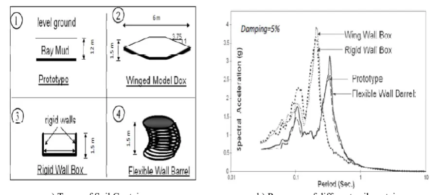
[image:48.595.108.562.450.651.2]There are mainly two types of containers, namely laminar container and plastic barrel that have been utilised for dynamic study in the literature. The laminar soil container consists of a rectangular hollow section made by aluminium frames. Rubber layers separate those frames. The function of aluminium frames is to provide lateral confinement of soil, while the function of rubber layer is to allow the soil shear deformation (Prasad et al., 2004; Meymand et al., 2000; Hokmabadi et al., 2014b).
Figure 2-17 Comparison of different types of soil container by Moss et al., (2010)
30 test (Maymand et al., 2000). Furthermore, Maymand et al., (2000) considered and compared three different types of soil containers (rigid, wing and flexible barrel containers) in his numerical study, where 12.19 m deep deposit of San Francisco Bay mud was used as a soil case study sample. The results showed that the flexible wall container precisely simulates the soil prototype while the rigid and wing wall containers do not replicate the behaviour of soil under dynamic conditions (Figure 2-17). To validate the numerical prediction, Maymand et al., (2000) tested the plastic barrel experimentally on a shaking table. Also, Crosariol (2010) and Moss et al. (2011) tested both flexible barrel and laminar containers, where the flexible barrel container provided the best response. Furthermore, the laminar container is complicated and expensive to construct. Therefore, flexible container with stiffening rings was adopted in this study. Moss et al. (2011) drew two conclusions. Firstly, the flexible barrel container and the relevant constructional details should be adequately conducted to minimise the box effect. Secondly, the container diameter should be five times the structure width. Hence, the dimensions of the container were selected as 1m diameter and 1m depth. The flexible container consists of 5 mm membrane cylinder wall supported individually by stiffener strips. The top part of the container was supported by lifting hooks from an overhead crane. The bottom base was set on the shaking.
Building code recommendation for Soil Foundation structure
Interaction (SFSI)
31 Modification of dynamic properties of the structure; or Modelling the subsoil with springs and dashpots (Lumped Parameter method)
BSSC (1997) recommendations include a procedure with details to incorporate the soil-structure interaction effects in the seismic design to determine the applied earthquake forces and estimate the lateral structure deflections. These soil-structure interactions have a defective impact on the base shear force applied on the structure, and consequently overturning moments can either increase or reduce the lateral structure deflections. The guidelines of NEHRP (2003) for new buildings to be designed are based on structure capacity and seismic demand. Seismic demand is a function of the base shear force which mainly depends on the equal mass first mode acceleration of response spectra. Inertial interaction effects are calculated by analysis of a period lengthening ratio and damping factor. These effects modify the value of base shear and lateral deflections of the structure. BSSC (1997) allows for up to 30% reduction in base shear due to soil structure interaction. The modified base shear value under soil-structure interaction influence (𝑣̃ ), the ratio of modified base shear to the base shear of the fixed-base structure (𝑣̃ / v) as well as the structural height (h), and the rocking stiffness of the subsoil foundation are employed by the code to determine the modified lateral deflections of the structure due to SSI.
32 increases the period. Compared to the simple fixed base case, the modified system now takes into account a lengthened period and increased damping.
The 2010 National Building Code of Canada (Mitchell et al., 2010), presented that the effects of soil-structure interaction on the seismic response of most buildings are favourable, and thus it is considered to be conservative to ignore it. Therefore, the seismic provisions of the proposed NBCC (2010) recommend performing soil-structure interaction analysis for alternative structures only. Eurocode 8, (Code, 2005) Design of Structures for Earthquake Resistance, highlights that soil-structure interaction effects are required to be considered in the design of the structures based on the followings:
• Structures sensitive to P-𝛥 effects • Massive structures
• Slender, tall structures (slender), and
• Structures supported by soft soil (Vs< 100 m/s)
For the mentioned structures, based on Lumped Parameter method, appropriate spring and dashpot coefficients are proposed for different subsoil conditions.
According to Amirsardari et al. (2014), Earthquake Actions in Australia does not include the soil-structure interaction effects in the structure design under seismic effect. Consequently, designers of the structure are not able to include those significant implications in the analysis and design procedure.
Using alternative design methods to consider the soil-foundation-structure interaction is allowed by the seismic design codes based on seismic requirements with the local authorities approval.
33
Soil-Foundation-Structure Interaction (SFSI)
Recent improvements in seismological source modelling led to significant advances in estimation procedures for the effects of soil–foundation-structure interaction under seismic on structural design. Estimation of effects of earthquake motions load on the constructions is the most critical phase of structures engineering design. When the structure is built on the solid rock and affected by seismic actions, the high stiffness of the rock forces the motion of rock to be almost close to the free-field motion. Therefore, for the analysis purposes, structures constructed on the solid rock are assumed to be fixed base structures. On the other hand, if the same structure is founded on soft soil, it would respond differently from solid rock. It is obvious that the dynamic structure responds with an additional deformation due to the soft soil deformation. The soil reaction influences the motion of the structure including a different type of foundation and vice versa. This is referred to as the soil –foundation- structure Interaction (SFSI).
2.11.1 Soil Structure Interaction under Seismic effect (Theoretical Studies)
The unavailability of standards and validated analytical techniques for estimating the soil-foundation-structure interaction (SFSI) leads to either simplifying or ignoring the interaction (Tabatabaiefar, 2012; Massimino and Maugeri, 2013). Hence, the structural and geotechnical aspects of the foundations are analysed individually when it comes to seismic studies. The motions of soil influence the structural response, which is referred to as soil-structure interaction (Kramer, 1996).Geotechnical engineers may simplify a multi-degree of freedom to a single-degree of freedom oscillator, and on the other hand, structural engineers replace the non-linear behaviour of the structure with linear springs or ignore the soil-structure interaction altogether (Tabatabaiefar, 2012; Massimino and Maugeri, 2013; Hokmabadi et al., 2014b).
34 may significantly increase the overall displacement of the superstructure compared to the fixed foundation (Hokamabadi et al., 2014a; Guin and Banerjee, 1998; Han, 2002). This increase in total deformation may lead to structural instability due to the secondary moment at the base (Ma et al., 2009). Hence, the foundation and superstructure design of high-rise buildings should be considered as a performance-based soil-structure interaction (SSI) issue and not limited to traditional empirically based design methods such as a bearing capacity approach with an applied factor of safety (Poulos et al., 2016). Therefore, the process of designing high-rise buildings has changed over the past years. In most recent years, it is not unusual to model full three-dimensional finite element models of the buildings without considering the effect of soilfoundation -structure interaction (Hallebrand et al., 2016).
35 Guin and Banerjee (1998) proposed a procedure to evolute the dynamic interaction of soil-pile foundation-structure system . A generalised formulation of finite element boundary was used to simulate the entire model.The formulation was conducted in the frequency domain. The excitation input was defined as a rock outcrop motion which was propagating S waves vertically. The linear dynamic analysis was performed on two cases. One was a multi-storey structure, while the other was a bridge. It was observed that soil-structure interaction has a significant impact on the structural system behaviour under seismic effects. Spyrakos and Xu (2003) considered the response of a large flexible strip foundation under seismic effects. The strip foundation was embedded in layered soils during the seismic excitation. A finite element formulation modelled the foundation. The modelling difficulty was the soil boundary element. The soil element was modelled as an infinitely extended boundary element formulation. The soil-structure system response was investigated, and the boundary effect was studied.
Wegner et al. (2005) proposed a numerical procedure to determine the dynamic interaction of soil-structure. Scaled boundary finite element was adopted in the modelling of the unbounded soil, while the standard finite element method was used in modelling of the superstructure. The dynamic response of tall buildings with multi-level basements under the effect of dynamic excitations was investigated. P, SV and SH waves at different angles have been included in this study.
Takewaki and Kishida (2005) proposed an analysis method for pile-group effects on the building response under the dynamic effects to study the building stiffness and strength with pile foundations. A dynamic Winkler type was used to simulate the soil element and pile within soil pile structure system. The effect of pile group was accounted for by considering the influence of coefficients defined for estimation of the pile-head bending moments and the storey drifts. It was found that the pile group effect increased the bending moments applied at the pile head and reduced the storey drift of buildings.
36 linear finite element procedure for a complete dynamic analysis was developed to investigate the soil-pile interaction and radiation damping in the frequency domain. Three types of soil profiles were studied together with a real recorded earthquake as input motions. The response of parameters to the effect on structure response or deformation like deflections, inter-storey drifts, accelerations and stress resultants was evaluated. The output results were compared with those obtained from the fixed base model. It was concluded that performing complete soil-structure interaction analysis is a more reliable evaluation compared to actual response of prototype system.
Galal and Naimi (2008) conducted a comprehensive numerical study of a multi-storey structure with 20 stories for soil-structure interaction under the seismic effects resting on three categories of site classes (IBC 2009), category B, C and D which are categorised based on shear wave velocity. Based on the output results, when the supporting soil is rock or very dense soil the structure can be assumed as a fixed base. For the structures constructed on the soft soils with shear wave velocity less than 600 m/sec site classes E, D and lower limit of C (360 m/s < 𝑣𝑠 < 600 m/s) were considered, where the structure deformation has a significant difference in comparison with fixed base structure.
37 which are used in response-based approaches for evaluation of the base shear forces and deformations in structures.
El Ganainy and El Naggar (2009) considered the seismic behaviour of a multi-storey structure constructed on subsoil classes C (360 m/s < 𝑣𝑠 < 750 m/s) and E (𝑣𝑠 <180 m/s) by IBC2000 under the effect of soil-structure interaction response. They concluded that structural deformations of the construction resulted due to the effect of soil-structure interaction response. Lateral deformations of the buildings with flexible bases experience significant amplification ranging from 50% to about 300% in comparison to the fixed bases for buildings founded on soil class E (Vs < 180 m/s).
Kutanis and Elmas (2001) presented an idealised 2-dimensional strain finite element to evaluate the dynamic effect on soil-structure interaction (SSI). The analysis was performed based on a substructure method using developed software to estimate the impact of soil-structure interaction. The linear SSI analysis and non-linear SSI analysis were conducted. The same structure was analysed with and without soil-structure interaction. These computations were studied varying the effect of accelerations and different soil condition as well as different shear wave velocity.
Available theoretical modelling methods for SFSI analysis are as follows. Two primary methods include Substructure method and Direct method.
Substructure method: In this method, the soil-pile-structure system is divided into near-field and far-near-field cases. According to Kramer (1996). This assumption is based on linear relations between soil behaviour and structure behaviour.
Direct method: In this method, there are three main steps as follows: