International Journal of Emerging Technology and Advanced Engineering
Website: www.ijetae.com (ISSN 2250-2459, ISO 9001:2008 Certified Journal, Volume 9, Issue 2, February 2019)
87
Performance of a Homing Head Control System Used for the
Proportional Navigation Method with PID Controller
Ahmed Ali Alarbash
Master Degree in Electrical Engineering and Computing, Model Signals and Systems, Singidunum University, 32 Danijelova Street, 11000, Belgrade
Abstract— The homing systems are generally speaking constructed from three components, the guidance law, the target tracking system, and the missile flight control system. The planned guidance system is capable to pursuit and hit any target simply by specifying the specified missile flight time. In our paper we are deals with general concept of homing guidance systems, types ofnavigation systems, and the simulation of our modeling. We try to find the optimal stabilization of homing head guidance by using PID controller and gyros, in three different structures and models with three different inputs as sight angles to find the homing head angular rates, static errors, tracking angles, control parameters values and making the comparison between all results to chose which of possible structures has the best performance of stabilization to use. Finally, the simulation of homing scenario with proportional navigation, comparisons have been done in order to evaluate proposed control and stabilization system relative to an ideal homing loop guidance system.
Keywords—: homing head, guidance, gyro, PID controller,
simulation by Mat lab software.
I. INTRODUCTION
The guidance system is strongly connected to the navigation system since precise position and timing are crucial. The implementation of guidance commands is usually pre-set, unless major position errors are found along the flight.
The types of guidance systems are characterized by the fact that the command signals are formed at the missile, based on the information coming from the target. Depending on the part of electro- magnetic spectrum in which the energy radiated or reflected by target, the homing system trackers can be of radar, infrared (IR), Optical or Thermo vision (TrV) type. [1], [2], [7] .The
stability for closed loop system is proved supported the Lyapunov stability theory, and the relationship between the accuracy of the impact angle and the estimate errors of disturbances [2].
The homing systems encompass three categories depending on the location of emitter, as: Active systems, Semi active systems and Passive systems. The paper is organized as follows:-
General ideas of homing guidance systems using PID controller and gyro in different structures.
Simulation of proportional navigation homing head guidance using (PN) of ideal homing loop( with differential), structure(1) and structure (2), as head stabilization and to make comparison between all of it, in miss distances in meter(m) and acceleration demands in (m/s2) with deferent target accelerations (non maneuvering and maneuvering target) with deferent homing head error and proper types of controller for structure(1) and structure(2) by using Mat Lab and simulink software's.
Simulation of Proportional navigation homing guidance with free gyro and PID controller as stabilization of homing head.
Comparing the simulation results for both types and final conclusion about it.
II. TYPES OF NAVIGATION SYSTEMS
A.Proportional navigation (PN) :- A missile system employed with homing guidance can sense and detect the target, guide itself to steer towards the target by generating commands to its own control surfaces. Proportional Navigation as a successful guidance law and it's is used in most of homing guidance systems. [1], [7]
International Journal of Emerging Technology and Advanced Engineering
Website: www.ijetae.com (ISSN 2250-2459, ISO 9001:2008 Certified Journal, Volume 9, Issue 2, February 2019)
88
In tactical IR missile applications of proportional navigation, the LOS rate is measured, whereas the closing velocity is estimated. Generally, the applications using aerodynamic control are not convenient for the use of true proportional navigation. [1], [2]Theoretically, it is possible by the appropriate control of thrust force magnitude, but technical realization of this type of control is much more difficult than benefits obtained. Also, in all cases where LOS angle and flight path angle are approximately equal (head on attack, tail chase), the differences between TPN and PPN vanish. [1], [7], [8]. In practice, the missile is usually not launched exactly on a collision triangle, since the expected intercept point is not known precisely. The intercept point can only be approximated. Any initial angular deviation of the missile from the collision triangle is thought as a heading error (HE). [1], [3], [4], [5]
III. HOMING HEAD STABILIZATION METHODS The target trackers used in homing missiles are usually called homing heads. [7] Their functions are the same as in all other trackers, but an on-board location is something making them specific, especially form the aspect of their space stabilization. Additionally, space and energy limits are also the facts affecting their design homing can be based on active, semi-active, and passive principle. According to this, the sensors in homing heads are receiving electromagnetic energy coming from the target, either as a source of radiation or the reflector of energy emitted from homing head itself or from some third location. [1], [3], [4], [5], [7]
A.Homing head stabilization provided by a rate gyro (ideal loop)
-
-+ +
+ +
TRTR
TR
TR
TRG
s
GRG sRG u
s
[image:2.612.335.551.151.249.2]
Fig. 1 Homing Head Stabilization based on Rate Gyro [7]
As shown in Figure 1 illustrates the homing head stabilization provided by a rate gyro .The rate gyro output is just approximately proportional to the required value of angular rate, needed for the realization of proportional navigation. [1], [7].
B.Homing Head Stabilization based on Free Gyro in Feedback loop as shown in figure (2)
-+
uTR
M
TR
1
1 1
K s
2
2 1
K s
1
Hs
Homing head electronics
[image:2.612.348.539.435.518.2]Torq motor Free gyro
Fig. 2 Homing Head Stabilization based on Free Gyro in Feedback loop [7]
Homing head assembly is now given by the blocks representing electronic part, torque motor, and the free gyro. Under the input of torque moment, M, free gyro makes precession (about the axis perpendicular to spin axis and input axis).The tracker angle will be the time integral of precession rate, proportional to input momentum. [7]
C.Homing Head Stabilization using Rate Gyro in Feedback loop.
One of the possible structures used for isolation of homing head from missiles motion and its stabilization in actual direction of target is shown on Figure 3, the rate gyro is now applied in feedback path. [1]
-+
TR
1
1 1
K s
Homing head electronics
-+
TR
2
2 1
K s
s
TR
+ + TR
u
Homing head mechanics
Fig. 3 Homing Head Stabilization using Rate Gyro in Feedback loop. [7]
IV. EXPERIMENTAL AND SIMULATIONS
Simulation of proportional navigation homing head guidance systems: -
[image:2.612.61.269.532.621.2]International Journal of Emerging Technology and Advanced Engineering
Website: www.ijetae.com (ISSN 2250-2459, ISO 9001:2008 Certified Journal, Volume 9, Issue 2, February 2019)
89
Our assuming is the missile velocity vm = 300 m/s.,
closing velocity vc = 600 m/s. Flight time tF = 10 second.
Tm =1 sec., navigation constant (c or Nprim ) =3.
acceleration demands of target ( nt ) (nt1= 0 , nt2 = 2 , nt3 =
4 ). Homing head errors He = (0, 0.1, 0.17) in radian. The practical simulation of homing guidance systems by using three structures of proportional navigation and PID controller in different cases are shown below.
Simulation of Proportional navigation ideal homing loop
Proportional navigation homing guidance with rate gyro and PI controller as stabalization of homing head . (structure 1)
Simulations of Proportional navigation homing guidance with free gyro and PID controller as stabilization of homing head. (structure 2)
[image:3.612.330.559.304.491.2]1- Simulation of Proportional navigation ideal homing loop The miss distance(m) with nt = 0 and, He (0, 0.1, 0.17) in radian as shown in figure 4
Fig. 4 The miss distance(m), nt = 0
[image:3.612.48.287.361.516.2]The acceleration demands(m/s2) with nt = 0 and He (0, 0.1, 0.17) in radian, as shown in figure.5
Fig. 5 Acceleration demands(m/s2) , nt = 0
Table 1 shows the comparing between miss distance and main parameters ,when the target acceleration (nt = 0 ) and head error has He = (0, 0.1, 0.17) in radian
TABLE 1
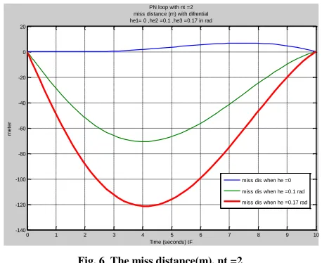
The miss distance with nt = 2 , (maneuvering target ), and He = (0, 0.1, 0.17), as shown in figure 6
Fig. 6 The miss distance(m), nt =2
[image:3.612.331.559.530.684.2]The acceleration demands(m/s2) with nt = 2 and He = (0, 0.1, 0.17) in radian as shown in figure 7
Fig. 7 Acceleration demands(m/s2), nt = 2
0 1 2 3 4 5 6 7 8 9 10
-120 -110 -100 -90 -80 -70 -60 -50 -40 -30 -20 -10 0 10 20
Time (seconds) tF
m
et
er
PN loop with nt =0 miss disrance with difrential case he1=0 ,he2= 0.1 ,he3 = .017 in rad
miss dis when he=0 miss dis when he=0.1rad miss dis when he=0.17rad
0 1 2 3 4 5 6 7 8 9 10 11
-20 -10 0 10 20 30 40 50
Time (seconds) tF = 10 s
a
cce
la
ra
tio
n
d
e
m
a
n
d
s
m
/s2
ideal homing loop PN loop with nt = 0 acceleration demands for ideal homing loop
he1 = 0 , he2 = 0.1 ,he2 = 0.17 in rad
acc.when he=0 acc.when he=0.1rad acc.when he=0.17 rad
0 1 2 3 4 5 6 7 8 9 10
-140 -120 -100 -80 -60 -40 -20 0 20
Time (seconds) tF
m
e
te
r
PN loop with nt =2 miss distance (m) with difrential he1= 0 ,he2 =0.1 ,he3 =0.17 in rad
miss dis when he =0 miss dis when he =0.1 rad miss dis when he =0.17 rad
0 1 2 3 4 5 6 7 8 9 10 11
-20 -10 0 10 20 30 40 50
Time (seconds) tF = 10s
a
cc
. m
/s2
PN homing with nt = 2 acceleration demands for ideal homing loop
he1 =0 ,he2 = 0.1 , he3 = 0.17 in rad
acc when he =0 acc when he =0.1 rad acc when he =0.17 rad nt = 0
He in ( Radian)
Miss Distan ce (m)
Peak Value of
Miss Distance
(m)
Time of Max. Miss Distance
of tF
Acc. at the end of tF
(m/s2)
He1 = 0 0.076 10 m 6.7 s 4.925
He2= 0.1 0.066 66.43 4 s 29.15
[image:3.612.47.289.550.706.2]International Journal of Emerging Technology and Advanced Engineering
Website: www.ijetae.com (ISSN 2250-2459, ISO 9001:2008 Certified Journal, Volume 9, Issue 2, February 2019)
90
[image:4.612.65.283.181.270.2]Table 2 shows the comparing between main parameters, when the target acceleration (nt = 2 ) and head error has He = (0, 0.1, 0.17) in radian
TABLE 2
[image:4.612.49.290.299.467.2]The miss distance(m) with nt = 4 (maneuvering target ) and, He = (0, 0.1, 0.17) as shown in figure 8
Fig. 8 The miss distance(m), nt = 4
[image:4.612.325.567.329.477.2]The acceleration demands(m/s2) with nt = 4 and He = (0, 0.1, 0.17) in rad. , as shown in figure 9
Fig. 9 Acceleration demands(m/s2), nt = 4
Table 3 shows the comparing between main parameters ,when the target acceleration (nt = 4) and head error has He = (0, 0.1, 0.17) in radian
TABLE 3
2- Proportional navigation homing guidance with rate gyro and PI controller as stabilization of homing head, with P controller =1.31827 and I controller = 11.153057 as (structure1)
The simulation results of Structure (1) :-
The miss distance (m) with nt = 0 and He (0, 0.1, 0.17) in radian as shown in figure 10
Fig.10 The miss distance(m), nt =0
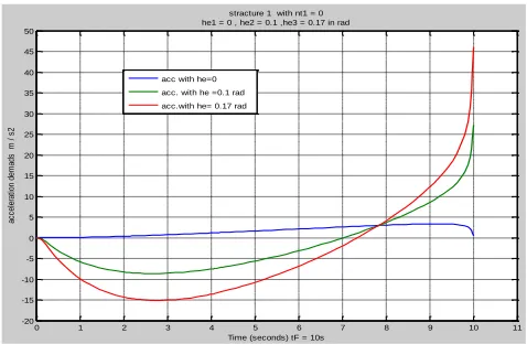
The acceleration demands(m/s2) with nt = 0 and, He (0, 0.1, 0.17) in radian. as shown in figure 11
Fig.11 Acceleration demands(m/s2), nt = 0
0 1 2 3 4 5 6 7 8 9 10
-140 -120 -100 -80 -60 -40 -20 0 20
Time (seconds) tF
m
et
er
PN loop with nt =4 miss distance (m) with difrential he1 = 0 ,he 2 = 0.1 , he3 = 0.17 in rad
miss dis when he =0 miss dis when he =0.1 rad miss dis when he =0.17 rad
0 1 2 3 4 5 6 7 8 9 10 11
-20 -10 0 10 20 30 40 50 60 70
Time (seconds) tF
a
cc.
m
/s
2
ideal homing loop with nt = 4 acceleration demands with difrential he1 = 0 ,he2 = 0.1 ,he3 = 0.17 in rad
acc when he = 0 acc when he = 0.1rad acc when he = 0.17 rad
0 1 2 3 4 5 6 7 8 9 10
-120 -110 -100 -90 -80 -70 -60 -50 -40 -30 -20 -10 0 10 20
Time (seconds) tF
m
is
s
di
st
an
ce
in
m
et
er
stracture 1 with nt = 0 head error in rad ( he1 =0 ,he2 = 0.1 , he3 = 0.17 ) vm=300 m/s , vc =600 m/s , Tm =1 , Nprin or c = 3
miss dis with he1 miss dis. with he2 miss dis.with he3
0 1 2 3 4 5 6 7 8 9 10 11
-20 -15 -10 -5 0 5 10 15 20 25 30 35 40 45 50
Time (seconds) tF = 10s
a
cc
el
er
at
io
n
de
m
ad
s
m
/
s
2
stracture 1 with nt1 = 0 he1 = 0 , he2 = 0.1 ,he3 = 0.17 in rad
acc with he=0 acc. with he =0.1 rad acc.with he= 0.17 rad nt = 2
He in ( Radian)
Miss Distance
(m)
Peak Value of
Miss Distance
(m)
Time of Max. Miss Distance
of tF
Acc. at the end of tF
(m/s2)
He1 = 0 0.086 6.86 m 7 s 8.41 He2= 0.1 0.076 70.65 m 4 s 32.52 He3 =0.17 0.068 121.37 4 s 49.5
nt = 4 He in ( Radian)
Miss Distance
(m)
Peak Value of
Miss Distance
(m)
Time of Max. Miss Distance
of tF
Acc. at the end of tF
(m/s2)
[image:4.612.49.290.500.667.2] [image:4.612.325.564.513.669.2]International Journal of Emerging Technology and Advanced Engineering
Website: www.ijetae.com (ISSN 2250-2459, ISO 9001:2008 Certified Journal, Volume 9, Issue 2, February 2019)
91
Table 4 shows the comparing between main parameters, when the target acceleration ( nt = 0 ) and head error is He (0, 0.1, 0.17) in radian
TABLE4
[image:5.612.353.567.148.226.2]The miss distance (m) with nt = 2 and, He (0, 0.1, 0.17) in radian as shown in figure 12
Fig.12 The miss distance(m), nt = 2
[image:5.612.328.560.262.431.2]The acceleration demands(m/s2) with nt = 2 and, He (0, 0.1, 0.17) in radian, as shown in figure 13
Fig.13 Acceleration demands(m/s2), nt = 2
Table 5 shows the comparing between main parameters, when the target acceleration ( nt = 2 ) and He (0, 0.1, 0.17) in radian
TABLE 5
The miss distance (m) with nt = 4 (maneuvering target ) and He (0, 0.1, 0.17) in radian, as shown in figure 14
Fig.14 The miss distance(m), nt = 4
[image:5.612.59.277.303.469.2]The acceleration demands(m/s2) with nt = 4 and, He (0, 0.1, 0.17) in radian. as shown in figure 15
Fig.15 Acceleration demands(m/s2), nt = 4
Table 6 shows the comparing between main parameters ,when the target acceleration ( nt = 4 ) and He = (0, 0.1, 0.17) in radian
0 1 2 3 4 5 6 7 8 9 10
-140 -130 -120 -110 -100 -90 -80 -70 -60 -50 -40 -30 -20 -10 0 10 20
Time (seconds) tF
m
is
s
d
is
ta
n
c
e
i
n
m
e
te
r
stracture 1 with nt =2 he1=0 ,he2 =0.1 , he3 = 0.17 (in rad)
0 1 2 3 4 5 6 7 8 9 10 11
-20 -10 0 10 20 30 40 50
Time (seconds) tF = 10 s
a
c
c
.
m
/
s
2
stracture 1 with nt = 2 acceleration demands he1 = 0 , he2 = 0.1, he3 = 0.17
acc. when he=0 acc. when he =0.1 rad acc. when he =0.17 rad
0 1 2 3 4 5 6 7 8 9 10
-140 -120 -100 -80 -60 -40 -20 0 20
Time (seconds)
m
is
s
d
is
ta
n
c
e
i
n
m
e
te
r
satracure 1 with nt = 4
miss distance in meter with he1 = 0 , he2 = 0.1 he3 =0.17 in rad
miss distance when he=0 miss distance when he = 0.1 rad miss distance when he =0.17 rad
0 1 2 3 4 5 6 7 8 9 10 11
-20 -10 0 10 20 30 40 50 60
Time (seconds) tF =10 s
a
c
c
e
la
ra
tio
n
d
e
m
a
n
d
s
in
m
/
s
2
stracure 1 when nt = 4 acceleration demands he1=0 ,he2 = 0.1 , he3 = 0.17 in rad
acc when he =0 acc. when he = 0.1 rad acc. when he =0.17 rad nt = 0
He in ( Radian)
Miss Distance
(m)
Peak Value of
Miss Distance
(m)
Time of Max. Miss Distance of
tF
Acc. at the end of tF
(m/s2)
He1 = 0 0.0427 10.093 6 .8 s 0.505 He2= 0.1 0.4656 67.59 4 s 27.258 He3 =0.17 0.82 119.12 4 s 45.98
nt = 4 He in ( Radian)
Miss Distance
(m)
Peak Value of
Miss Distance
(m)
Time of Max.
Miss Distance
of tF
Acc. at the end of tF
(m/s2)
He1 = 0 0.159 4.45 8 s 8.45
He2= 0.1 0.665 73.1843 4.15 s 35.2
[image:5.612.326.562.461.645.2] [image:5.612.56.279.499.675.2]International Journal of Emerging Technology and Advanced Engineering
Website: www.ijetae.com (ISSN 2250-2459, ISO 9001:2008 Certified Journal, Volume 9, Issue 2, February 2019)
92
TABLE 6
3- Simulations of Proportional navigation homing guidance with free gyro and PID controller as stabilization of homing head. (Structure 2)
The type of controller which is used for the simulation of structure 2 is P controller which tuned at (1.567231)
[image:6.612.324.567.261.423.2]The miss distance(m) with nt = 0 and He (0, 0.1, 0.17) in radian, as shown in figure 16
Fig.16 The miss distance(m), nt = 0
[image:6.612.50.299.321.481.2]The acceleration demands(m/s2) with nt = 0 and He = (0, 0.1, 0.17) in radian as shown in figure 17
Fig.17 Acceleration demands(m/s2), nt = 0
Table 7 shows the comparing between main parameters ,when the target acceleration ( nt = 0 ) and head error has He = (0, 0.1, 0.17) in radian
TABLE 7
The miss distance (m) with nt = 2 and He = (0, 0.1, 0.17) in radian .as shown in figure 18
Fig.18 The miss distance(m), nt = 2
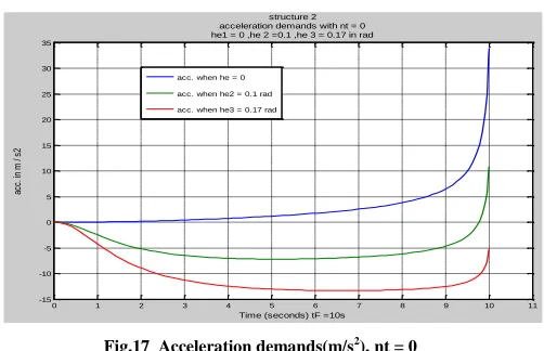
[image:6.612.328.561.458.638.2]The acceleration demands (m/s2) with nt = 2 and He = (0, 0.1, 0.17) in radian, as shown in figure 19 .
Fig.19 Acceleration demands(m/s2), nt = 2
Table 8 shows the comparing between main parameters, when the target acceleration ( nt = 2 ) and He = (0, 0.1, 0.17) in radian
0 1 2 3 4 5 6 7 8 9 10 11
-180 -160 -140 -120 -100 -80 -60 -40 -20 0 20
Time (seconds) tF 10 s
m
is
s
di
st
an
ce
in
m
et
er
structure 2 miss distance with nt1 = 0 he1 = 0 , he2 = 0.1 , he3 = 0.17 in rad
miss dis when he = 0 miss dis when he = 0.1 rad miss dis when he = 0.17 rad
0 1 2 3 4 5 6 7 8 9 10 11
-15 -10 -5 0 5 10 15 20 25 30 35
Time (seconds) tF =10s
ac
c.
in
m
/
s2
structure 2 acceleration demands with nt = 0 he1 = 0 ,he 2 =0.1 ,he 3 = 0.17 in rad
acc. when he = 0 acc. when he2 = 0.1 rad acc. when he3 = 0.17 rad
0 1 2 3 4 5 6 7 8 9 10 11
-180 -160 -140 -120 -100 -80 -60 -40 -20 0 20
Time (seconds) tF =10s
m
is
s
di
st
an
ce
in
m
et
er
structure 2 miss distance with nt 2 = 2 he1 =0 , he2 = 0.1 he3 = 0.17 in rad
0 1 2 3 4 5 6 7 8 9 10 11
-20 -10 0 10 20 30 40 50
Time (seconds) tF = 10 s
a
c
c
e
le
ra
tio
n
d
e
m
a
n
d
s
m
/
s
2
structure 2 with nt = 2 he1 = 0 ,he2 = 0.1 , he3 =0.17 in rad
acc. when he1=0 acc. when he2=0.1 rad acc. when he3 = 0.17 rad nt = 2
He in ( Radian)
Miss Distance
(m)
Peak Value of
Miss Distance
(m)
Time of Max. Miss Distance
of tF
Acc. at the end of tF
(m/s2)
He1 = 0 0.012 7 7.4 s 3.03 He2= 0.1 0.52 71.5 4.2 s 29.75 He3 =0.17 0.875 123.5 4 .04s 48.5
nt = 0 He in ( Radian)
Miss Distance
(m)
Peak Value of
Miss Distance
(m)
Time of Max. Miss Distance
of tF
Acc. at the end of tF
(m/s2)
[image:6.612.48.299.513.675.2]International Journal of Emerging Technology and Advanced Engineering
Website: www.ijetae.com (ISSN 2250-2459, ISO 9001:2008 Certified Journal, Volume 9, Issue 2, February 2019)
[image:7.612.317.571.99.671.2]93
TABLE 8
[image:7.612.61.576.104.683.2]The miss distance (m) with nt = 4 (maneuvering target ) and He = (0, 0.1, 0.17) in radian, as shown in figure 20
Fig.20 The miss distance(m), nt = 4
[image:7.612.50.287.450.616.2]The acceleration demands (m/s2) with nt = 4 and He = (0, 0.1, 0.17) in radian, as shown in figure 21
Fig.21 Acceleration demands(m/s2), nt = 4
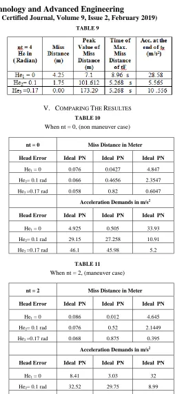
Table 9 shows the comparing between main parameters, when the target acceleration ( nt = 4 ) and He = (0, 0.1, 0.17) in radian
TABLE 9
V. COMPARING THE RESULTES
TABLE10
When nt = 0, (non maneuver case)
TABLE 11
When nt = 2, (maneuver case)
0 1 2 3 4 5 6 7 8 9 10 11
-180 -160 -140 -120 -100 -80 -60 -40 -20 0 20
Time (seconds) tF = 10s
m
is
s
di
st
an
ce
in
m
et
er
structure 2 miss distance with nt3 = 4 he1= 0 , he2 = 0.1 , he3 = 0.17 in rad
miss dis when he1 =0 miss dis when he2 =0.1 rad miss dis when he3 = 0.17 rad
nt = 2 He in ( Radian)
Miss Distance
(m)
Peak Value of
Miss Distance
(m)
Time of Max. Miss Distance
of tF
Acc. at the end of tF
(m/s2)
He1 = 0 4.645 11.06 8.325 s 32 He2= 0.1 2.1449 97.706 5.133 s 8.99 He3 =0.17 0.395 169.27 5.2665 821.7
nt = 0 Miss Distance in Meter
Head Error Ideal PN Ideal PN Ideal PN
He1 = 0 0.076 0.0427 4.847
He2= 0.1 rad 0.066 0.4656 2.3547
He3 =0.17 rad 0.058 0.82 0.6047
Acceleration Demands in m/s2
Head Error Ideal PN Ideal PN Ideal PN
He1 = 0 4.925 0.505 33.93
He2= 0.1 rad 29.15 27.258 10.91
He3 =0.17 rad 46.1 45.98 5.2
nt = 2 Miss Distance in Meter
Head Error Ideal PN Ideal PN Ideal PN
He1 = 0 0.086 0.012 4.645
He2= 0.1 rad 0.076 0.52 2.1449
He3 =0.17 rad 0.068 0.875 0.395
Acceleration Demands in m/s2
Head Error Ideal PN Ideal PN Ideal PN
He1 = 0 8.41 3.03 32
He2= 0.1 rad 32.52 29.75 8.99
International Journal of Emerging Technology and Advanced Engineering
Website: www.ijetae.com (ISSN 2250-2459, ISO 9001:2008 Certified Journal, Volume 9, Issue 2, February 2019)
94
TABLE 12
When nt = 4, (high maneuver case)
VI. DISCUSSION
- In case of He1 = 0 , the minimum miss distance (0.159
m) and minimum acceleration demands (8.45 m/s2 ) is occurred with structure (1) .
- In case of He2 = 0.1 rad. , the minimum miss distance
(1.02 m) is occurred with structure (1) , but the minimum acceleration demands (5.565m/s2) is occurred with structure (2).
- In case of He3 = 0.17 rad., the minimum miss distance (
0.00) which is the best and minimum acceleration demands (10.556 m/s2 ) is occurred with structure (2) where the acceleration demands for the others is too high.
Structure (1) :-
The proportional navigation homing guidance with rate gyro and PI controller as stabilization of homing head has high performance at all different modes of target acceleration (non maneuvering target), where the miss distance and the acceleration demands are acceptable.
Structure (2) :-
The proportional navigation homing guidance with free gyro and P controller as stabilization of homing head, has acceptable performance for non maneuvering target modes, and high performance with maneuvering target .
The acceleration demands and miss distance are depending on the value of heading error (He) and on the kind of target acceleration(nt) , where in all cases of bout structures, the acceleration are increased with increasing of (nt and He) . Finally both structures can be considered as the best homing guidance models from the performance and the stability point view.
The appropriate choosing of one of them is depending on the type of target and its motion characteristics .
VII. CONCLUSIONS
The PN is one of the best proven techniques which have been used extensively in past and present homing systems. The difference between the free gyro and the rate gyro is, the free gyro has two degrees of freedom but, the rate gyro has one degree of freedom. All our simulation results, with different types and values of sight angles are acceptable from angular rates, tracking angles and static errors point view. From the homing scenario with proportional navigation systems, we have to know the main target characteristics and the characteristics missile motion.
The minimum miss distance and the acceleration demands ,which are the important parameters of homing guidance systems can be optimized by find the proper kind of homing guidance loop by chosen and tuning the PID controller, until getting the minimum miss distance and an acceptable acceleration demands to attack the target. In our simulations, it's easy to apply the characteristics of the target and the missile, and it's possible to improve the performance of the homing head system.
Acknowlgements
My Acknowledgement for all who are helps me in my life.
REFERENCES
[1] Alqudsi, Y. S., & El-Bayoumi, G. M. (2018). A Qualitative Comparison between the Proportional Navigation and Differential Geometry Guidance Algorithms. INCAS BULLETIN, 10(2).
[2] Yang, S., Guo, J., & Zhou, J. (2018). New Integrated Guidance and Control of Homing Missiles with an Impact Angle against a Ground Target. International Journal of Aerospace Engineering, 2018.
[3] He, S., & Lee, C. H. (2018). Optimality of Error Dynamics in Missile Guidance Problems. Journal of Guidance, Control, and Dynamics, 1-10.
[4] Zheng, D., Lin, D., Xu, X., & Tian, S. (2017). Dynamic stability of rolling missile with proportional navigation & PI autopilot considering parasitic radome loop. Aerospace Science and Technology, 67, 41-48.
[5] Palumbo, N. F., Blauwkamp, R. A., & Lloyd, J. M. (2010). Basic principles of homing guidance. Johns Hopkins APL Technical Digest, 29(1), 25-41.
[6] Zarchan, P. (2007). Tactical and Strategic Missile Guidance (Progress in Astronautics and Aeronautics). AIAA.
[7] Graovac, S. (2005). Automatsko vođenje objekata u prostoru. Akademska misao,(in Serbian) Beograd,
[8] Zhong, J. (2006). PID controller tuning: A short tutorial. Mechanical Engineering
[9] Chen, Z., Liu, X. and Chen, W., 2017. Design of real-time hardware-in-the-loop tv guidance system simulation platform. International Journal of Aerospace Engineering, 2017.
nt = 4 Miss Distance in Meter
Head Error Ideal PN Structure1 Structure 2
He1 = 0 0.144 0.159 4.25
He2= 0.1 rad 0.134 0.665 1.75
He3 =0.17 rad 0.128 1.02 0.00
Acceleration Demands in m/s2
Head Error Ideal PN Structure1 Structure 2
He1 = 0 20.52 8.45 28.58
He2= 0.1 rad 44.73 35.2 5.565
![Fig. 3 Homing Head Stabilization using Rate Gyro in Feedback loop. [7]](https://thumb-us.123doks.com/thumbv2/123dok_us/8678300.874050/2.612.348.539.435.518/fig-homing-head-stabilization-using-rate-gyro-feedback.webp)