A Comparative Study of 5-level and 7-level
Multilevel Inverter Connected to the Grid
Nurul Aisyah Yusof
1, Norazliani Md Sapari
1,2, Hazlie Mokhlis
1,2, Jeyraj Selvaraj
2 1Department of Electrical Engineering, Faculty of Engineering, University of Malaya,University of Malaya, 50603 Kuala Lumpur, Malaysia
2University of Malaya Power Energy Dedicated Advanced Center (UMPEDAC), Level 4, Wisma R&D, University
of Malaya, 59990 Kuala Lumpur, Malaysia
Abstract—Power electronic converters were developed for integrating the photovoltaic (PV) arrays and utility grid. Inverters are needed to convert the direct current electricity produced by the PV array into alternating current electricity required for loads. Nowadays, multilevel inverter gained so much popularity in PV systems. Multilevel inverter promises a lot of advantages over conventional inverter especially for high power applications. Some of the advantages are that the output waveform were improved since multilevel inverter produced nearly sinusoidal output voltage waveforms, hence the total harmonic distortion also low. The switching losses also become less. And, the filter needed to smooth the output voltage is small; hence, the system is compact, lighter and much cheaper.
Keywords--5-level, 7-level multilevel inverter, PWM modulation technique, power factor, THD, efficiency.
I.
I
NTRODUCTIONPhotovoltaic system or PV system is a system that converts sunlight into electricity. Converting the sun’s radiation directly into electricity is done by solar cells. These cells are made of semiconducting materials. When sunlight is absorbed by these materials, the solar energy knocks electrons loose from their atoms, allowing the electrons to flow through the material and hence produce electricity [1]. The electricity converted by the cells is in direct current (DC). A grid-connected PV system will require a DC-to-AC inverter. This device will convert the DC electricity produced by the PV array into alternating current. PV system is one of the electricity sources as mentioned above. The
DC-to-AC converter produces some impacts to distribution network. Harmonic problems occur as the inverters have too high capacitance. When harmonic happens, resonance problems will then occur, leading to high harmonic currents and voltages [2].
For DC-to-AC converter, multilevel inverter is a good choice for PV system application. This is because it provides quite a lot of advantages. Therefore, at the end of this paper, 5-level multi5-level inverter’s simulation output will be compared with 7-level multilevel inverter, focusing on power factor, total harmonic distortion (THD), and its efficiency. Hence, the better level of multilevel inverter will be concluded.
II.
T
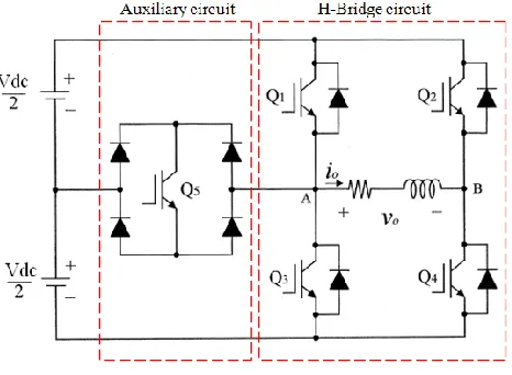
HEORY A. 5-level Multilevel Inverter [image:1.612.52.285.526.697.2]For 5-level inverter, the topology is presented in Figure 1. This topology consists of a full-bridge inverter, an auxiliary circuit (comprises of one switching element and four diodes) and two capacitors as voltage divider. The multilevel inverter is connected after the dc power supply. The main point of the auxiliary circuit is to generate half level dc supply voltage [3]. It also reduced the layout complexity compared to other multilevel inverter topology such as flying-capacitor topology, diode-clamped topology and hybrid topology, and these topologies can be studied in various papers such as in [4] and in [5]. The operations of the new topology were presented in literature [3], [6] and [7]. The output voltage levels according to the switch on-off conditions were tabulated in Table I. The switch in auxiliary circuit must be properly switched considering the direction of the load current.
TABLE I. THE SWITCHES ON-OFF CONDITION FOR 5-LEVEL MULTILEVEL INVERTER
Output
Voltage Q1 Q2 Q3 Q4 Q5
+Vdc 1 0 0 0 1
+Vdc/2 0 0 0 1 1
0 0 0 1 1 0
-Vdc 0 1 0 0 1
B. 7-level Multilevel Inverter
[image:2.612.49.288.246.465.2]The topology of 7-level inverter is similar to 5-level topology, only the auxiliary circuit now was added with an additional circuit. In general, 7-level inverter consists of a full-bridge inverter, two bidirectional switches (the auxiliary circuit), and three capacitors as voltage divider illustrated in Figure 2. To ensure that the power flows from the PV arrays to the grid, high dc bus voltages are necessary. LCL filter is used to filter the current to be injected into the utility grid. Seven output voltage level can be achieved when the switching signal for the IGBTs in the topology were done properly. The required seven levels of output voltage are generated, and the operation was explained in literature [8]. The switching combinations that generated the seven output voltage levels tabulated in Table II.
Figure 2. Topology of 7-level multilevel inverter
TABLE II. THE SWITCHES ON-OFF CONDITION FOR 7-LEVEL MULTILEVEL INVERTER
Output
Voltage Q1 Q2 Q3 Q4 Q5 Q6
+Vdc 1 0 0 1 0 0
+2Vdc/3 0 0 0 1 1 0
+Vdc/3 0 0 0 1 0 1
0 0 0 1 1 0 0
0* 1 1 0 0 0 0
-Vdc/3 0 1 0 0 1 0
-2Vdc/3 0 1 0 0 0 1
-Vdc 0 1 1 0 0 0
Note: “1” for ON, “0” for OFF
C. Power Factor
Power factor is the ratio between real power and apparent power in a circuit. The formula for power factor is
(1)
where θ is the angle difference (in degrees) between output voltage and output current. Unity power factor is the best. The load with higher power factor will draw less currents, hence decrease the lost in distribution system and therefore wasted energy will be less.
D. Total Harmonic Distortion (THD)
THD is a measurement of the harmonic distortion is defined as the ratio of the sum of the powers of all harmonic components to the power of the fundamental frequency. It can be presented by expression below
(2)
Formula above is for the current waveform. THD is used to characterize the linearity of a systems and the power quality of electric power systems.
According to IEEE standard of THD limits, total harmonic current distortion shall be less than 5% of the fundamental frequency current at rated inverter output [9]. The THD for simulated model will be shown in Section IV.
E. Efficiency
In general, efficiency is a measurable concept, quantitatively determined by the ratio of output to input. In this system, input power is the power delivered from PV arrays, while the output power is the power at the grid. PV array’s voltage must be higher than of Vgrid to inject current into the grid, or current will be injected from the grid into the inverter. This means that PV arrays must be the one that deliver the power for the grid, so that the grid can consume the power.
III.
M
ODULATIONT
ECHNIQUEA. PWM Modulation Technique for 5-level Multilevel Inverter
Figure 3. PWM switching signal generation for 5-level multilevel inverter.
According to the amplitude of the voltage reference, Vref, the operational interval of each mode varies within a certain period. The modes are separated as [3]
Mode 1:
0
t
1&
2
t
Mode 2:
1
t
2Mode 3:
t
3&
4
t
2
Mode 4:
3
t
4The phase depends on the modulation index. The modulation index of the proposed five-level PWM inverter is defined as [10]
2
m
c
A
M
A
(3)where AM is the peak value of reference voltage and AC is the peak value of carrier wave. The modulation index recommended in this technique is to be between 0.66 and 1.
B. PWM Modulation Technique for 7-level Multilevel Inverter
Seven level multilevel inverter’s PWM modulation contain three reference signal named Vref1, Vref2, and Vref3. These three reference signals had same frequency, amplitude and phase. The difference is that they had different offset values. The reference signals are positive sine waveform. To produce the signals for the switches, the reference signals need to be compared to a carrier signal (Vcarrier); a triangular wave signal, using a comparator.
The reference signals were each compared with the carrier signal. If Vref1 had exceeded the peak amplitude of Vcarrier,
Vref2 was then compared with Vcarrier until it had exceeded the peak amplitude of Vcarrier. Then, Vref3 would be compared with Vcarrier until it reached zero. Once Vref3 had reached zero, Vref2 would be compared until it reached zero. Then, onward, Vref1 would be compared with Vcarrier [8] and the process continues. Figure 4 shows the signal generation.
Six modes were operated in one cycle of this inverter and described as follows [8]
Mode 1:
0
t
1&
4
t
Mode 2:
1
t
2&
3
t
4 Mode 3:
2
t
3Mode 4:
t
5&
8
t
2
Mode 5:
5
t
6&
7
t
8 Mode 6:
6
t
7The phase angle depends on modulation index. For dual reference signal used in 5-level modulation technique, equation (1) was used. Therefore, for three reference signals, the modulation index is defines as [8]
3
mc
A
M
A
(4)IV.
S
IMULATIONS, R
ESULTS ANDD
ISCUSSIONSFor simulation purposes, PSCAD/EMTDC software was used. The model simulated consists of PV array, multilevel inverter, LCL filter and grid system.
A. PV Array
The inverter was tested with a PV array of 75W. The module’s ratings are shown in Table III. Ten modules connected in series were used in this simulation. The value of reference irradiance and reference temperature were needed for PV modules provided by PSCAD/EMTDC software and the following values had been chosen.
TABLE III. PV MODULE CHARACTERISTIC
Max Power 7.5W
Short Circuit Current, Isc 20.5A
Open Circuit Voltage, Voc 12.5V
Reference Irradiance 1000 W/m2
Reference Temperature 250C
B. PWM Implementation
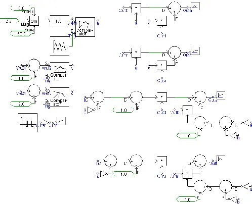
[image:3.612.65.278.630.703.2]Figure 5. Implementation of PWM for 5-level multilevel inverter
Figure 6. Implementation of PWM for 7-level multilevel inverter
The PWM switching signals for both multilevel inverters are shown in Figure 7 and Figure 8.
C. Grid
The grid used in this simulation was an AC source that can act as the load, as well as a distribution system. The RMS voltage of the grid is 240V and it has no source impedance, (ideal mode), with a frequency of 50Hz.
D. 5-level Multilevel Inverter
[image:4.612.58.307.259.461.2]The model of 5-level inverter grid connected is shown in Figure 9.
Figure 7. PWM switching signals for 5-level multilevel inverter.
[image:4.612.321.578.365.647.2]Figure 9. Model of 5-level multilevel inverter
Figure 10 shows the simulation result of inverter output voltage, Vinv. As seen from Figure 9, boost converter has been added after PV array. The purpose of the addition is because as mentioned in efficiency section, PV array’s output voltage was 500 V since Vout was 240 V. But PV array voltage only 175V. Therefore, the boost converter will boost the DC voltage output of PV array from only 175V, up to 500V, with duty cycle of 65%. Using modulation index’s equation given by (3), the value of M is 0.83.
Vinv comprises of five voltage levels that are
,
, 0,
,
2
2
Vdc
Vdc
Vdc
Vdc
. The current flowing into the grid was filtered to resemble a pure sine wave in phase with the grid voltage (see Figure 11). As Iout is almost a pure sine wave at unity power factor, the total harmonic distortion (THD) can be reduced. Result of power factor and THD are shown in Figure 12 and Figure 13 respectively. A THD calculator in PSCAD software had been used to calculate the THD. For power factor, mathematical simulation of equation (1) had been done.Figure 10. Simulation result of 5-level multilevel inverter voltage output
Figure 11. Filtered output current and voltage
Figure 13. THD of 5-level multilevel inverter
E. 7-level Multilevel Inverter
Figure 14 shows the 7-level multilevel inverter model. The output of the inverter is shown in Figure 15. Filtered current and voltage that flow to the grid also presented in Figure 16. And lastly, the profile of power factor and THD analysis were illustrated in Figure 17 and Figure 18 respectively. This simulation’s modulation index M is similar to 5-level multilevel inverter which is 0.83, calculated using (4).
Figure 14. Model of 7-level multilevel inverter
Figure 15. Simulation result of 7-level multilevel inverter voltage output
Figure 16. The filtered current and voltage flowing into the grid
Figure 18. THD of 7-level multilevel inverter
As for the efficiency, output power of 5-level multilevel inverter is 50.7 W, while 7-level multilevel inverter gave 66.4 W of output power. Both model had been used the same PV array’s characteristic and the power of it is 75 W. Therefore the efficiency of 5-level multilevel inverter is 67.9% and for 7-level multi7-level inverter is 88.5%.
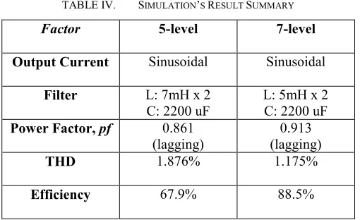
From the results presented, we can summarize it as in Table IV.
TABLE IV. SIMULATION’S RESULT SUMMARY Factor 5-level 7-level
Output Current Sinusoidal Sinusoidal
Filter L: 7mH x 2 C: 2200 uF
L: 5mH x 2 C: 2200 uF
Power Factor, pf 0.861
(lagging) (lagging) 0.913
THD 1.876% 1.175%
Efficiency 67.9% 88.5%
From Table IV, it shows that the values of filters used in 7-level multi7-level inverter are smaller than filters used in 5-7-level multilevel inverter. The smaller the filter size, the less cost needed to implement the model.
The power factor also shows that 7-level multilevel inverter is closer to unity power factor than 5-level multilevel inverter. As widely known, unity power factor is ideal because it means that no energy wasted in the system. In reality, closing the value of power factor to 1 is as far as it can be and power factor value of 7-level multilevel inverter is better than the value for 5-level multilevel inverter.
For the THD value, both levels had given the results that satisfy the IEEE standard of THD limit as mentioned in Section II, which is below 5%. Therefore, both levels have acceptable value of THD, despite 7-level multilevel inverter having smaller THD compared to 5-level multilevel inverter.
For the efficiency, it is obvious that 7-level multilevel inverter gave better efficiency value than 5-level and that means 7-level multilevel inverter is more efficient than the other.
C
ONCLUSIONThe use of multilevel inverter in PV system was accepted in power system since it gave a lot of advantages. More number of levels of multilevel inverter will give better performance in the system. In this paper, from the simulations and the results, 7-level multi7-level inverter had given more efficient performance in terms of the power factor, THD and its efficiency than 5-level multi5-level inverter. It also is more suitable for the purpose of integrating PV arrays and grid system.
A
CKNOWLEDGMENTThis work was supported by the Malaysian Government and University of Malaya, Kuala Lumpur under HIR/MOHE research Grant (Grant Code: D000004-16001) and Postgraduate Research Grant IPPP (Grant no: PS009-2012A )
R
EFERENCES[1] European Commision, "A Vision of Photovoltaic Technology", Directorate-General for Research Sustainable Energy Systems, EUR 21242, 2005.
[2] Annexes, “Publications review on the impacts of PV Distributed Generation and Electricity networks”, PVUpscale, Intelligent Energy
Europe, 2008.
[3] S.J. Park, F.S. Kang, M.H. Lee, C.U. Kim, "A New Single-Phase Five-Level PWM Inverter Employing a Deadbeat Control Scheme", IEEE Transactions on Power electronic, Vol. 18, No. 3, May 2003, pp. 831-843. [4] A. K. Panda, Y. Suresh, “Research on Cascade Multilevel Inverter with Single DC Source by using Three-phase Transformers”, Electrical Power
and Energy System, Vol 40, March 2012, pp. 9-20.
[5] B. Singh, N. Mittal, K. S. Verma, “Multi-Level Inverter: A Literature
Survey On Topologies And Control Strategies”, International Journal of Reviews in Computing, Vol. 10, July 2012, pp. 1-16.
[6] G. Cerlia, V. Grau, C. Sanchez, F. Ibanez, J. Walter, A. Millan, M.I Gimenez, "A New Multilevel Inverter Topology", in Fifth IEEE International Caracas Conference on Devices, Circuits and Systems, Dominican Republic, November 2004, pp. 212-218.
[7] G. Cerlia, V. Guzman, C. Sanchez, F. Ibanez, J. Walter, M.I. Gimenez, "A New Simplified Multilevel Inverter for DC-AC Conversion", IEEE Transactions on Power Electronics, Vol. 21, No. 5, September 2005, pp. 1311-1319.
[8] N.A. Rahim, K. Chaniago, J. Selvaraj, "Single-Phase Seven-Level Grid Connected Inverter for Photovoltaic System", IEEE Transactions on Industrial Electronics, Vol. 58, No. 6, June 2011, pp. 2435-2443. [9] IEEE Std 929-2000, “IEEE Recommended Practices for Utility Interface
of Photovoltaic Systems”.
[10] V.G. Agelidis, D.M. Baker, W.B. Lawrance, C. V. Nayar, "A Multilevel Inverter Topology for Photovoltaic Applications", in IEEE International
Sysmposium on Industrial Electronics, ISIE ’97, Vol. 2, July 1997, pp. 589-594.
[image:6.612.47.302.306.462.2]