International Journal of Emerging Technology and Advanced Engineering
Website: www.ijetae.com (ISSN 2250-2459,ISO 9001:2008 Certified Journal, Volume 5, Issue 5, May 2015)
477
A Partner Selection Techniques in Wireless Cooperative
Communication with Effective Power Saving.
Abhinav G Sodhaparmar
1, Prof. Puram Gour
2, Prof. Paramjeet kour
3 1Power Electronics Department, NRI Collage, Bhopal, India 2Head of Dept of Electronics in NRI College at Bhopal, India
3Asst. Proffesor in NRI College at Bhopal, India
Abstract-- With the revolution in technology, most of the communication systems are going to be wireless. But wireless communication performance is badly ejected by channel fading. One of the possible solutions is MIMO, but it is not always possible to provide more than one antenna, due to size constraints. So virtual MIMO, known as cooperative diversity was introduced, to provide diversity. This report presents a study of network with source, destination and relay, deferent transmission protocols and relay selection techniques. In cooperative wireless networks, it is often the case that multiple sources and multiple relays cooperate to transmit their data to destination. For the cooperative systems, selecting an appropriate relay node is of prime importance. Various relaying algorithms are used to select appropriate relay. In this report, the algorithm, namely greedy and exchange algorithm, is used for relay selection. It aims to minimize the total transmission power in the multi source and multi relay wireless networks in which one source has only one partner to help for information transmission. Later on, based on the analysis and the mechanism used in GAEA, an alternative version of GAEA is provided, that enhances the algorithm for more optimized result.
Keywords— Multi-source, Multi-relay, Relay selection technics.
I. INTRODUCTION
Now a days wireless communications have gained much popularity in recent years due to its ability to provide unbound connectivity and mobile access. But reliable and high data-rate communication over the wireless channel has been unsuccessful due to multipath fading, shadowing, and path loss effects. One of the possible solution is to develop effective transmit and receive diversity techniques to exploit diversity in different channel dimensions, such as time, frequency, and space, and achieve the so-called diversity gains. Multiple-input multiple-output (MIMO) systems have made it desirable to embed multiple antennas on modern wireless transceivers, inorder to achieve spatial diversity
gains
.
The increasing numbers of users demanding service have encouraged intensive research in wireless communications.
The problem with the cooperative communications is the unreliable medium through which the signal has to travel. To mitigate the effects of wireless channel, the idea of diversity has been deployed in many wireless systems. Diversity is a communication technique where the transmitted signal travels through various independent paths and thus the probability that all the wireless paths are in fade is made negligible. Frequency diversity, time diversity and space diversity are the three basic techniques for providing diversity to the wireless communication systems.
Multiple-input multiple-output (MIMO) systems, where the transmitters as well as receivers are equipped with multiple antennas, proved to be a breakthrough in wireless communication system which offered new degree of freedom, in spatial domain, to wireless communications. After that, MIMO became part of many modern wireless communications standards like LTE Advanced, WiMAX and Wireless LAN.. Though, the idea of cooperative communication was given in 2003 by Sendonaris[5], it is still considered an extensive research which is going to exploit its benefits in the next generation communication systems.
II. MIMOSYSTEMS
International Journal of Emerging Technology and Advanced Engineering
Website: www.ijetae.com (ISSN 2250-2459,ISO 9001:2008 Certified Journal, Volume 5, Issue 5, May 2015)
478
The idea of cooperation was presented by van der Meulen in 1971, which established foundation of relay channel. Cooperative communication takes advantage of broadcast nature of the wireless medium where the neighbouring nodes overhear the source’s signals and relay the information to the destination.
Each mobile has one antenna and cannot individually generate spatial diversity. However, it may be possible for one mobile to receive the other, in which it can forward some version of "overheard" information along with its own data. Because the fading paths from two mobiles are statistically independent, this generates transmit diversity.
[image:2.595.147.450.238.446.2]In Cover and El Gamal [2], three node network consisting of a source, a destination, and a relay. It was assumed that all nodes operate in the same band, so the system can be decomposed into a broadcast channel from the viewpoint of the source and a multiple access channel from the viewpoint of the destination. The relay channel model is shown in Fig 3. In this model, transmitter A sends a signal X, whose noisy, attenuated version is received by both the destination C and a relay B. The relay then transmits another signal X1 to the destination, based on what it has received.
Figure 3: Relay Channel
This model can be decomposed into a broadcast channel (A transmitting, B and C receiving), and a multiple access channel (A and B transmitting, C receiving).
Figure 4: In Cooperative Communication each mobile is both a relay and a user
III. COOPERATIVE COMMUNICATION
[image:2.595.328.534.511.611.2]International Journal of Emerging Technology and Advanced Engineering
Website: www.ijetae.com (ISSN 2250-2459,ISO 9001:2008 Certified Journal, Volume 5, Issue 5, May 2015)
479
Cooperation leads to interesting tradeoffs in code rates and transmit power. In the case of power, it may seem that more power is required because, in cooperative mode, each user is transmitting for both itself and a partner. However, the point to be made is that the gain in diversity from cooperation allows the users to reduce their transmit powers and maintain the same performance. In the face of this tradeoff, one hopes for a net reduction of transmit power, given everything else being constant. Similarly for the rate of the system. In cooperative communication, each user transmits both its own bits as well as some information for its partner, so it may appear that each user requires more bandwidth. On the other hand the spectral efficiency of each user improves because, due to cooperation diversity, the channel code rates can be increased. Thus to summarize, in non-cooperative communication users send directly to a common destination, without repeating for one another.The received signal can be written as :
Yd;r = hd;rX2 + nd;r = hd;rhr;sX1 + hd;rnr;s + nd;r (1)
Where hd; r is the channel from the relay to the destination nodes and nr;s is the noise signal added to hd;r. In cooperative wireless, users not only transmit their own information, but also repeat other users' information during its transmission to a common destination. During the first slot, Base station receives from user1
Ys; d = X1hs; d + ns; d (2)
Where Ys;d is the signal received at destination from source, X1 is the transmitted signal, hs;d is the channel gain and ns;d is the AWGN noise. In the next time slot, it receives the relayed version of the same information from its partner, user 2 as
Yr; d = X1hs; d + ns; d (3)
Here Yr;d is the signal received at destination from relay or cooperating user, X1 is the transmitted signal of user 1, relayed be its partner, hr;d is the channel gain, and nr;d is the AWGN noise. These two copies of the same signal received at BS are combined and used by the receiver for decision making or decoding purpose.
IV. COOPERATIVE TRANSMISSION PROTOCOLS
[image:3.595.59.265.667.741.2]A. Amplify and Forward Method
Figure 5: Amplify and Forward method [4].
Laneman and Wornell first proposed amplify-and-forward as a cooperative signaling scheme in [4]. Amplify-and-forward is conceptually the most simple of the cooperative signaling method. In this method, each user receives a noisy version of the signal transmitted by its partner; the user then amplifies and retransmits this noisy signal (see Fig 5).The destination will combine the information sent by the user and partner and will make a final decision on the transmitted symbol. Although the noise of the partner is amplified , the destination still receives two independently-faded versions of the signal and is thus able to make better decisions for the transmitted symbols. A potential challenge in this scheme is that sampling, amplifying, and retransmitting analog values may be technologically non-trivial.
Nevertheless, amplify-and-forward is a simple method that lends itself to analysis, and therefore has been very useful in furthering the understanding of cooperative communication system.
B. Decode and Forward Method
The first work proposing a detect-and-forward protocol for user cooperation was by Sendonaris, Erkip, and Aazhang [5]. Nowadays a wireless transmission is very seldom analogue and the partner has enough computing power, so Detect and Forward is most often the preferred method to process the data in the partner. The received signal is first decoded and then re-encoded. So there is no amplified noise in the sent signal, as is the case using Amplify and Forward protocol. There are two main implementations of such a system. The partner can decode the original message completely. This requires a lot of computing time, but has numerous advantages. If the source message contains an error correcting code, received bit errors might be corrected at the partner station. Or if there is no such code implemented a checksum allows the partner to detect if the received signal contains errors. Depending on the implementation an erroneous message might not be sent to the destination. But it is not always possible to fully decode the source message. The additional delay caused to fully decode and process the message is not acceptable, the partner might not have enough computing capacity or the source message could be coded to protect sensitive data. In such a case, the incoming signal is just decoded and re-encoded symbol by symbol. So neither an error correction can be performed nor a checksum calculated.
[image:3.595.332.535.682.759.2]International Journal of Emerging Technology and Advanced Engineering
Website: www.ijetae.com (ISSN 2250-2459,ISO 9001:2008 Certified Journal, Volume 5, Issue 5, May 2015)
480
C. Compress and Forward Method
The main difference between compress-and forward and decode/amplify-and-forward is that in the later the partner transmits a copy of the received message, while in compress and forward the relay transmits a quantized and compressed version of the received message. Therefore, the destination performs the reception function by combining the received message from both source node and its compressed version from the partner node. The quantization and compression process at partner node is a process of source encoding, i.e., representation of each received message as a sequence of symbols. Let us assume that these symbols are binary digits (bits). At the destination, an estimate of the compressed message is obtained by decoding the received sequence of bits. This decoding operation involves mapping of received bits into a set of values that estimate the transmitted message. This mapping process normally involves the introduction of distortion, which can be considered as a form of attenuation and noise.
D. Coded Cooperation Method
Coded cooperation differs from the previous schemes such that the cooperation is implemented at the level of the channel coding subsystem. We know in both amplify and forward and decode-and-forward schemes, the partner repeats the bits sent by the source. In coded cooperation incremental redundancy at relay, which when combined at the receiver with the codeword sent by the source, results in a codeword with larger redundancy.
V. APPLICATIONS
•
Cooperative sensing for cognitive radio•
Wireless Ad-hoc Network•
Wireless Sensor Network•
Vehicle-to-Vehicle CommunionVI. PARTNER SELECTION TECHNIQUES
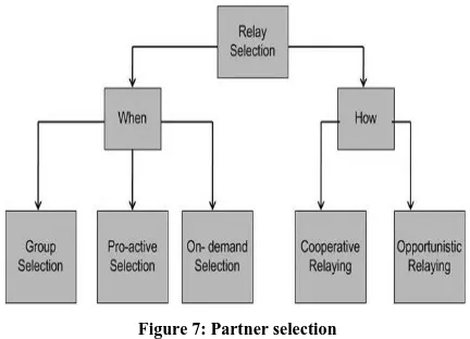
In cooperative communication, to choose the partner or relay or set of them, is the challenging task. The proper selection of the relay can effectively improve the overall performance of the network in terms of higher data rate/through put, lower power consumption and better bit error rate performance. The relay is based on the performance indices like Channel state information (CSI), Signal to noise ratio (SNR), Packet error rate (PER) etc. The relay is not to be selected by only considering the source to destination performance but it must be done by keeping the overall system performance in view. The relay selection can be classified as follows.
•
Group selection-
In this method, relay selection occursbefore transmission. The purpose of selection is to achieve certain pre-defined performance level
•
Proactive selection-
In this method relay selectionis performed by the source, the destination, or the relay itself during the transmission time
•
On-demand selection-
Here relay selection is [image:4.595.322.538.255.411.2]performed when needed i.e. when direct channel conditions decrease below a pre-defined threshold.
Figure 7: Partner selection
Depending on the relation between the network entities, relay selection mechanisms can be divided into two categories:
•
Opportunistic Partner Selection•
Cooperative Partner SelectionThe basic opportunistic relay selection scheme is based on local measurements. They can be further classified as
•
Measurement-based partner selection•
Performance-based partner selection•
Threshold-based partner selectionAll these three approaches are opportunistic and follow a proactive selection approach.
The on-demand selection category (e.g. Adaptive relay selection) follows a different approach, in which the relay selection procedure is only triggered if needed.
Contrary to opportunistic relay selection, cooperative relay selection procedures require the exchange of information among the involved communication nodes. In this case there are two categories:
Table-based relay selection that leads to the selection of a controlled number of relays (one or two) based on information kept by the source Contention-based relay selection that leads to the
International Journal of Emerging Technology and Advanced Engineering
Website: www.ijetae.com (ISSN 2250-2459,ISO 9001:2008 Certified Journal, Volume 5, Issue 5, May 2015)
481
[1] Measurement-based Partner Selection
Measurement-based relay selection approaches are characterized by requiring no topology information, being based only on local measurements of instantaneous channel conditions. This technique is proposed by H. Shan [6]. Measurement-based approaches are able to select the best relay among N devices, but for this they may require 2N channel state estimations.
[2] Performance-based Partner Selection
Performance-based selection approaches rely on performance criteria like delay and energy efficiency to select the most suitable relay [7]. The operation of performance- based selection approaches is as follows:
[3] Threshold-based Partner Selection
International Journal of Emerging Technology and Advanced Engineering
Website: www.ijetae.com (ISSN 2250-2459,ISO 9001:2008 Certified Journal, Volume 5, Issue 5, May 2015)
482
[4] Adaptive Partner Selection
Due to variations on channel conditions the PER of the link from source to destination may decrease in a way that relaying over a helping node is not needed. Adaptive relay selection approaches propose to perform relay selection only if relaying is needed with high probability. An example of adaptive relay selection is Adam et al. [9].
[5] Table-based Partner Selection
Table-based approaches [9] follow a cooperative relay selection process aiming to decrease the impact of relay selection on transmission time. Here sources keep CSI information about the links between themselves and potential relays as well as about the links from potential relays and each potential destination. The CSI information is gathered using RTS/CTS frames as well as information collected from overhead transmissions. Relays are selected by the source by looking up in a table. A node may be selected as relay if the transmission time over the direct link to a destination is higher than the sum of the transmission time over the source-relay and relay-destination links.
[6] Contention-based Partner Selection
International Journal of Emerging Technology and Advanced Engineering
Website: www.ijetae.com (ISSN 2250-2459,ISO 9001:2008 Certified Journal, Volume 5, Issue 5, May 2015)
483
VII. GREEDY AND EXCHANGE ALGORITHM
Greedy and Exchange algorithm, can be used to select appropriate relay node in the co-operative environment.
Here it is assumed that a system is of M source nodes and N relay nodes and one source has only one partner to help for information transmission.
S
iS
1S
MR
N RjR
1h
si,R
jhrj,d
[image:7.595.107.489.186.519.2]hs1,d
Fig. Source-Relay Network
The relay selection technique is used to minimize the total power required to transmit the information. Hence, in terms of power consumed by source node and relay node, the problem statement can be formulated as follows:
Where Psi indicates the power consumption of ith
source and Prj indicates power consumption of jth relay. In other words, the source-relay pair is selected such that the total powertransmitted is minimum.
First of all, we need to calculate the total transmission power for each possible source and relay pair, and initialize the elements in the transmission power matrix
International Journal of Emerging Technology and Advanced Engineering
Website: www.ijetae.com (ISSN 2250-2459,ISO 9001:2008 Certified Journal, Volume 5, Issue 5, May 2015)
484
Where Pi,j denote the minimum total transmission power when the i-th source cooperates with j-th relay to transmit the information. Specially, Pi,N+1 denote the direct transmission power without cooperation.
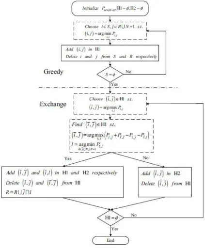
The GAEA consists of two phases. In the first phase, namely greedy phase, the source and relay pair corresponding the minimum power in the matrix
PM×(N+1) is added into Η1(intermediate allocation) until all the source nodes have been allocated. In the second phase, namely exchange phase, based on Η1, M
times exchange is carried out for the total power reduction. Firstly, from Η1 choose the source and relay pair (i, j) with maximum transmission power.
Then, from Η1 find the source and relay pair (I , J ) which can swap the relay with (i, j) to get the maximum power saving. If the source and relay pair (I , J ) is found, delete (i, j) and (I, J )from Η1 , and add (i, J ) and (I , j) in Η2(final relay allocation) and Η1 respectively. Notice that the source node I can choose to directly transmit the message, cooperate with the relays remained in R or cooperate with the relay j according to the total transmission power. If the source and relay pair is not found, add (i, j) in Η2, and delete (i, j) from Η1. Repeat
the process until Η1 is empty. Finally, according to Η2, the total transmission power can be achieved by summation of the corresponding elements of PM×(N+1) . Greedy Phase
International Journal of Emerging Technology and Advanced Engineering
Website: www.ijetae.com (ISSN 2250-2459,ISO 9001:2008 Certified Journal, Volume 5, Issue 5, May 2015)
485
Exchange [image:9.595.71.495.158.673.2]hase
Fig. 4.2 Flow Diagram of GAEA
1. Limitation of GAEA
From the simulation of the GAEA algorithm it has been found out that, it works well in DF-DT system. In DF-DT system, Direct Transmission from source node to destination is possible in addition to the relayed transmission.
International Journal of Emerging Technology and Advanced Engineering
Website: www.ijetae.com (ISSN 2250-2459,ISO 9001:2008 Certified Journal, Volume 5, Issue 5, May 2015)
486
The limitation with algorithm is that in case of DF system; where no direct transmission is possible; the exchange phase allocation tends to increase the total power transmission. This is because, when pair (i , j) i.e maximum power consuming pair in H1, swaps it relay with (I , J) forming (i , J), then the source I is forced to make pair with j owing to the fact that there is no direct transmission possible and other relays are occupied by different sources. This can possibly increase the total power consumption of the source I transmission to the destination via relay j.Note: This limitation has been found from our simulation of GAEA algorithm, which is shown in the later part of this article
2 Modified GAEA
In order to overcome the above mentioned limitation of the GAEA algorithm, we propose a modified version of GAEA which eliminates the possibility of increase in power consumption in the exchange phase.
Modified GAEA uses an additional step compared to GAEA. This additional step consists of a check to identify whether the total power consumption due to source-relay allocation in Exchange Phase is greater than the corresponding power consumed in the Greedy phase or not.
And, if it is so, then the instead of allocating source-relay pair as per H2(final allocation), source-relay selection is done based on H1(intermediate allocation) i.e the intermediate allocation in the Greedy Phase is kept as it is, and final relay selection is done on the basis of Greedy Phase result.
VIII. SIMULATION,RESULTS AND DISCUSSION
1 MATLAB Simulation of GAEA:
Simulation of GAEA algorithm is performed in simulation tool MATLAB. In DF environment, assuming that the power allocation is already done; we consider 5 sources and 5 relays for the simulation purpose, which can be changed as per requirement later on. Initially GAEA code and its output is shown, and then same code is run for 5 consecutive time to check out the limiting effect of the GAEA. Later on, code for Modified GAEA is shown and the results of GAEA and Modified GAEA are compared.
Total_power_Greedy_Phase = 51.1532
Table .1
The Greedy Phase intermediate relay allocation
---
Source Relay Power Consumption 2 5 1.0714
1 2 2.9262 3 1 3.8096 4 3 14.5613 5 4 28.7848
Total_power_Exchange_Phase = 55.2664
Table .2
The Exchange Phase Final relay allocation
---
Source Relay Power Consumption 2 5 1.0714
5 1 18.9708 4 3 14.5613 3 2 16.4064 1 4 4.2566
The above output shows the source-relay pair and their corresponding power consumption.
Total_power_Greedy_Phase and
Total_power_Exchange_Phase are the total transmission power in Greedy Phase and Exhange Phase repectively.
As seen from the above output, the maximum power consuming source-relay pair is 5-4 in H1 consuming 28.7848 unit power. In exchange phase, source 5 exchanges it relay with source 3 making pair source-relay 5-1 consuming 18.9708 unit power which is less than pervious pair 5-4.
But, though we succeeded in reducing power consumption of source 5, exchange phase has unknowingly increased power consumption of source 3 from 3.8096 to 16.4064 units which in turns increases the total power transmission.
International Journal of Emerging Technology and Advanced Engineering
Website: www.ijetae.com (ISSN 2250-2459,ISO 9001:2008 Certified Journal, Volume 5, Issue 5, May 2015)
[image:11.595.84.499.159.534.2]487
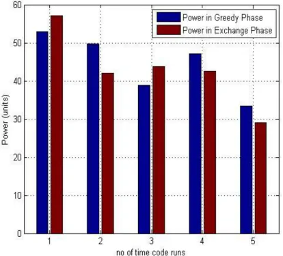
Fig. .1 Bar-graph of GAEA Simulation
The careful observation of the above graph shows that initially in the second, forth and fifth run the power in Exchange Phase is effectively reduced by GAEA algorithm but in first and third run, it fails to do so. The reason for this is, Exchange phase’s attempt to minimize the power consumption of maximum power consuming source relay pair by relay exchange, has increased the overall power consumption.
This can be seen in first and third run where brown stripes are higher than blue strips.
2 MATLAB Simulation of Modified GAEA:
Total_power_Greedy_Phase = 51.1532 Total_power_Exchange_Phase = 55.2664 Modified_Exchange_Phase =51.1532
The Greedy Phase intermediate relay allocation
--- Source Relay Power Consumption
International Journal of Emerging Technology and Advanced Engineering
Website: www.ijetae.com (ISSN 2250-2459,ISO 9001:2008 Certified Journal, Volume 5, Issue 5, May 2015)
488
The Exchange Phase Final relay allocation
--- Source Relay Power Consumption
2 5 1.0714 5 1 18.9708 4 3 14.5613 3 2 16.4064 1 4 4.2566
As seen from the above output, the maximum power consuming source-relay pair is 5-4 in H1 consuming 28.7848 unit power. In exchange phase, source 5 exchanges it relay with source 3 making pair source-relay 5-1 consuming 18.9708 unit power which is less than pervious pair 5-4.
But, though we succeeded in reducing power consumption of source 5, exchange phase has unknowingly increased power consumption of source 3 from 3.8096 to 16.4064 units which in turns increases the total power transmission.Hence relay selection is not made on the basis of H2, but it is made on the basis of H1 i.e intermediate allocation in the Greedy Phase.
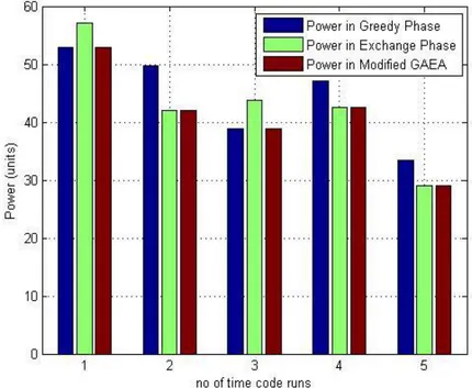
[image:12.595.75.505.357.710.2]3 Comparison of GAEA and Modified GAEA:
International Journal of Emerging Technology and Advanced Engineering
Website: www.ijetae.com (ISSN 2250-2459,ISO 9001:2008 Certified Journal, Volume 5, Issue 5, May 2015)
489
The above simulated comparison of the GAEA and Modified GAEA shows that the power consumption in Modified GAEA never exceeds that in the Exchange Phase.IX. CONCLUSION
By using cooperative diversity techniques, performance of wireless communication can be increased. With the help of cooperative diversity we can get results similar to the MIMO, but with less no of antennas. The diversity can be achieved by using relay along with source and destination in the network. The data is sent directly from the source to the destination or via the relay. Proper selection of the relay is a crucial task. In this, study of different relay selection techniques is done.
In this report, simulation of Greedy & Exchange algorithm with limited no of sources and relays is done. This algorithm is basically used to minimize the total transmission power required to transmit the information. From the simulation results it has been concluded that, power consumption in Exchange phase is effectively reduced, but sometimes it fails to do so.
Modified –GAEA algorithm developed as a part my thesis, which is an logical extension of the GAEA algorithm. This algorithms tends to minimize the overall power Consumption and at the same time overcome the limitation of GAEA, which has been clearly Shown and discussed in the Chapter 5. The simulated results and the comparison also shows that Modified-GAEA algorithm can be effectively used for the Relay Selection in Wireless Networks and gives better and more optimized output as compared to GAEA algorithm.
REFERENCES
[1] Juhi Garg, Priyanka Mehta and Kapil Gupta, "A Review on
Cooperative Communication Protocols in Wireless
World",(IJWMN) Vol. 5, No. 2, April 2013
[2] T. M. Cover and A.A.E. Gamal. “Capacity theorems for the relay channel” IEEE Trans. Info. Theory, vol. 25, no. 5, September 1979.
[3] K.-S. Hwang and Y.-C. Ko, “An Efficient Relay Selection Algorithm for Cooperative Networks,” in Proc. of IEEE VTC. [4] J. N. Laneman. “Cooperative diversity in wireless networks:
Algorithms and architectures.” Ph.D.Dissertation, Massachusetts Institute of Technology, August 2002.
[5] A. Sendonaris, E. Erkip, and B. Aazhang, “User cooperation diversity-part I: system description,” IEEE Trans. on Communication, vol. 51, pp. 1927-1938, Nov. 2003.
[6] H. Shan, W. Z. P. Wang, and Z. Wang, “Cross-layer Cooperative Triple Busy Tone Multiple Access for Wireless Networks,” in Proc. of IEEE Globecom, New Orleans, USA, Dec. 2008. [7] Z. Zhou, S. Zhou, J. Cui, and S. Cui, “Energy-Efficient
Cooperative Communications based on Power Control and Selective Relay in Wireless Sensor Networks,” IEEE Journal on Wireless Communications, vol. 7, no. 8, pp. 3066-3078, Aug.2008.
[8] W. P. Siriwongpairat, T. Himsoon, W. Su and K. J. R. Liu, “Optimum Threshold-Selection Relaying for Decode-and-Forward Cooperation Protocol,” in Proc. of IEEE WCNC, Las Vegas, USA, Apr. 2006.
[9] H. Adam, C. Bettstetter, and S. M. Senouci, “Adaptive Relay Selection in Co- operative Wireless Networks,” in Proc. of IEEE PIMRC, Cannes, France, Sep.2008.
[10] K. Tan, Z. Wan, H. Zhu, and J. Andrian, “CODE: Cooperative Medium Access for Multirate Wireless Ad Hoc Network,” in Proc. IEEE of SECON, California, USA, Jun. 2007.
![Figure 5: Amplify and Forward method [4].](https://thumb-us.123doks.com/thumbv2/123dok_us/8701170.879550/3.595.332.535.682.759/figure-amplify-and-forward-method.webp)