International Journal of Emerging Technology and Advanced Engineering
Website: www.ijetae.com (ISSN 2250-2459,ISO 9001:2008 Certified Journal, Volume 4, Issue 4, April 2014)
151
Simulation & Development of Inverter Fed Three Phase
Induction Motor Using V/f Control Strategy
Shaikh Elan
1, Apte Aishwarya
21M.E Electrical(Power Electronics & Drives) AISSMS, COE, Pune 2Assistant Professor AISSMS, COE, Pune
Abstract--Amongst all electrical motors, induction motors are the most widely used motors due to their reliability, low cost and robustness.
Out of the several methods of speed control of an induction motor, constant V/f speed control method is most widely used due to its simplicity. In this method, the V/f ratio is kept constant which in turn maintains the magnetizing flux constant so that the maximum torque remains unchanged. Thus, the motor is completely utilized in this method.
This paper presents the simulation and implementation of three Phase inverter fed induction motor drive by using 89c52 microcontroller. The proposed drive system for three Phase inverter is simulated using MATLAB/Simulink software. For simulation, the gating pulses of inverter are generated.
The hardware implementation of three phase inverter is also done and proved that the experimental results are same as that of simulation results. The hardware of inverter comprises of MOSFET’s,three-phase induction motor & microcontroller 89c52. It can be used in industrial drive control application.
Keywords– Inverter fedInduction motor, V/f control,
Microcontroller, MATLAB Simulink Simulation.
I. INTRODUCTION
Amongst many methods, V/f control (scalar control) is mostlyemployed for Speed Control of 3 phase Induction motor .
Scalar Control(V/f) of an Induction Motor
In this technique, the field orientation of the motor is not used. Instead, the frequency and the voltage are the main control variables and are applied to the stator windings. The status of the rotor is ignored, meaning that no speed or position signal is fed back. The drive is therefore regarded as an open-loop drive[1]. This type of drive is suitable for applications such as pumps and fans, which do not require high levels of accuracy or precision In short it is described as frequency controlled induction motor drive: This method involves changing synchronous speed by changing frequency of a.c. supply to induction motor to cause speed variation, as the true speed of the motor is very close to synchronous speed. This project is based on a voltage source inverter using this method of speed control.
Fig.1:Speed Torque Characteristics With v/f Control
As we can see in the speed-torque characteristics in fig1, the induction motor draws the rated current and delivers the rated torque at the base speed. When the load is increased (over-rated load), while running at base speed, the speed drops and the slip increases. The motor can take up to 2.5 times the rated torque with around 20% drop in the speed. Any further increase of load on the shaft can stall the motor. The torque developed by the motor is directly proportional to the magnetic field produced by the stator. So, the voltage applied to the stator is directly proportional to the product of stator flux and angular velocity. This makes the flux produced by the stator proportional to the ratio of applied voltage and frequency of supply .By varying the frequency, the speed of the motor can be varied. Therefore, by varying the voltage and frequency by the same ratio, flux and hence, the torque can be kept constant throughout the speed range.
Stator Voltage (V) ∝ [Stator Flux(φ)] x [Angular Velocity (ω)]
v ∝ φ x 2πf
φ ∝ v/f
International Journal of Emerging Technology and Advanced Engineering
Website: www.ijetae.com (ISSN 2250-2459,ISO 9001:2008 Certified Journal, Volume 4, Issue 4, April 2014)
152 The starting current requirement is low. The stable operating region of the motor is increased. This makes constant v/f,the most common speed control method of an induction motor.
II. PROPOESD DRIVE SYSTEM
Fig2: Detailed Block Diagram of Hardware
As shown in fig 2, Microcontroller 89c52 is used for control circuit.
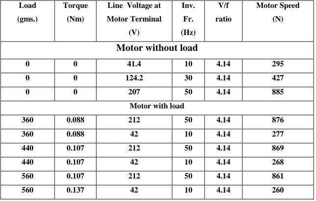
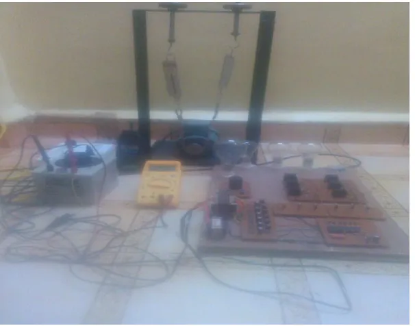
The complete hardware system has been developed and tested. The motor with ratings of 1440 RPM, 440V, 0.37Amp, 0.25 H.P. has been tested on no load to full load. The results are tabulated below.
III. IMPLEMENTATION
In thisproject, 0.25 HP induction motor withloadingarrangement (belt & pulley) is used.
Dip
Switches
Crystal oscillator 12 MHZ
Micro
Controller
89c52
2
Opto- Isolator
PIC
817
Circuit
Signal Amplifier
TIP
122
Regulated
+ 5 volt power supply
Opto Isolator and signal
amplifier gate driver
power supply
+ 12 volt
MOSFET
BASED
INVERTER
CIRCUIT
300 volt un-
Regulated
DC power
supply
230 volt AC mains supply
R
L
O
A
D
International Journal of Emerging Technology and Advanced Engineering
Website: www.ijetae.com (ISSN 2250-2459,ISO 9001:2008 Certified Journal, Volume 4, Issue 4, April 2014)
153 Observation Table no..1
Working:
The 5V regulated power supply is given to VCC of microcontroller. The input port of microcontroller is port 1 which accepts the data from DIP switches. Depending upon switch position ON and OFF, 1200 modes, frequency of output pulses is varied from 10Hz to 100Hz.
Port 0 of microcontroller is used as output port to have output pulses. These pulses are given to six Optoisolator which isolates the control circuitry from the power circuitry. The output of the Optoisolator is given to the signal amplifiers to amplify the signal up to the GATE requirement of the inverter. The TIP 122 Darlington pair of the transistors is used for the amplification of the output current of the Optoisolator.
The output of the signal amplifier is given to the inverter circuitry which in turn generates the three phase output.
A three phase output can be obtained from a configuration of six MOSFET connected in bridge configuration. Depending on the type of control signals applied to the gate of MOSFET, three phase inverter can operate in one of two possible modes of operation namely 180 degree conduction mode & 120 degree conduction mode.
Observations were taken before loading the motor & after loading it for different frequencies of inverter as per table no.1. .Results are compared after simulation by MATLAB Simulink simulation.
Load
(gms.)
Torque
(Nm)
Line Voltage at
Motor Terminal
(V)
Inv.
Fr.
(Hz)
V/f
ratio
Motor Speed
(N)
Motor without load
0 0 41.4 10 4.14 295
0 0 124.2 30 4.14 427
0 0 207 50 4.14 885
Motor with load
360 0.088 212 50 4.14 876
360 0.088 42 10 4.14 277
440 0.107 212 50 4.14 869
440 0.107 42 10 4.14 268
560 0.107 212 50 4.14 861
[image:3.612.146.468.147.352.2]International Journal of Emerging Technology and Advanced Engineering
Website: www.ijetae.com (ISSN 2250-2459,ISO 9001:2008 Certified Journal, Volume 4, Issue 4, April 2014)
[image:4.612.80.533.148.339.2]154
Fig 3: Simulation Block Diagram of V/f Control
The Fig 3 shows the simulation diagram of closed loop V/f control of three-phase induction motor. It consists DC source, three -phase PWM voltage source inverter which is built using an Universal Bridge Block and three phase induction motor as open loop in addition to that it has PI controller. Connecting the scope through bus selector .Now the simulation circuit is run with closed loop control shows speed of the induction motor ,motor current, speed & torque signals at the o/p block. The graphs are plotted as per the hardware results as shown in figures 4 & 5
IV. RESULTS
Fig 4: V/f Vs Speed without load
When inverter frequency is 50 Hz, the simulated torque & speed are as shown in fig 6 & 7.
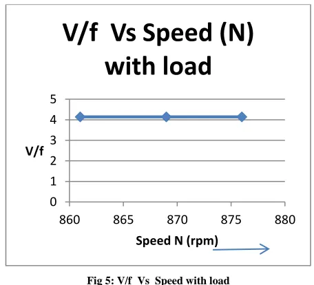
Fig 5: V/f Vs Speed with load
Changing an inverter frequency:-When the inverter frequency is changed from 50 Hz to 10 Hz, the following change in speed was observed & also the changed torque as per the Hardware results as shown in fig.
0 1 2 3 4 5
0 500 1000
V/f
Speed N (rpm)
V/f Vs Speed N
without load
01 2 3 4 5
860 865 870 875 880
V/f
Speed N (rpm)
V/f Vs Speed (N)
[image:4.612.329.557.389.596.2] [image:4.612.56.283.494.693.2]International Journal of Emerging Technology and Advanced Engineering
Website: www.ijetae.com (ISSN 2250-2459,ISO 9001:2008 Certified Journal, Volume 4, Issue 4, April 2014)
[image:5.612.157.460.414.652.2]155 Fig 8: Output Torque Waveform at 10 Hz
Fig 5.7: Output Speed Waveform at 10 Hz
Fig.6: Output Torque Waveform at 50 Hz
Fig7: Output Speed Waveform at 50 Hz
International Journal of Emerging Technology and Advanced Engineering
Website: www.ijetae.com (ISSN 2250-2459,ISO 9001:2008 Certified Journal, Volume 4, Issue 4, April 2014)
156 V. CONCLUSION
The speed of three-phase induction motor is being controlled by varying supply voltage and frequency with constant (V/f) ratio. .From the observation table no.1, it is clear that by maintaining constant v/f ratio, motor runs at variable speed with load & without load below rated speed. It is simple, economic & easier to design,& to implement in open loop. But the drawback of open loop is that, it doesn’t correct the change in output. Also it doesn’t reach the steady state quickly. These drawbacks can be overcome by modifying an open loop into a closed loop system. It can be realized by MATLAB simulation software.
The Hardware results are compared by MATLAB Simulation results & found matched with them.
REFERENCES
[1] Bose, B.K. 1986. "Power Electronics and Drives", Prentice-Hall, Englewood Cliffs, New Jersey
[2] Deepali Shirke, Haripriya Kulkarni ―Microcontroller based speed control of three phase Induction Motor using V/f method‖International Journal of Scientific and Research Publications, Volume 3, Issue 2, February 2013 1 ISSN 2250-3153. [3] R. Krishnan, ―Electric Motor Drive: Modeling, Analysis, and
control,‖ (Prentice Hall, 2001). Applicat., vol. 33, pp.202– 208,Jan./Feb. 1997.
[4] R Brindha ―Implementation of V/f Control of Three Phase Induction Motor using Microcontrolle‖r a project report of S. R M. College of Engineering Madras (July 2006)
[5] H.W. Van Der Broeck and J. D. VanWyk, ―A comparative investigation of a three-phase induction machine drive with a component minimized voltage-fed inverter under different control options,‖ IEEE Trans. Ind. Applicat., vol. IA-20, pp. 309–320, Mar./Apr. 1984.
[6] Adkins, B. 1957. "The General Theory of Electrical Machines", Chapman & Hall Ltd, London
[7] R. J. Kerkman, B. J. Seibel, D. M. Brod, T. M. Rowan, and D.Leggate, ―A simplified inverter model for on-line control and simulation,‖ IEEE Trans. Ind. Applicat., vol. 27, no. 3, pp. 567– 573,1991.
[8] F. Zeng Peng,‖ A Generalized Multilevel Inverter Topology with Self Voltage Balancing ―- IEEE Trans on Industry Applications Vol. 37, No. 2, pp 611-618, 2001.
[9] H. N. Hickok, ―Adjustable speed—A tool for saving energy losses in pumps, fans, blowers, and compressors,‖ IEEE Trans. Ind. Applicat.vol. IA-21, pp. 124–136, Jan./Feb. 1985.