&J
1::\
CONTf\.OL DATA
\::1
r::J
CO[\PO~TION
CDC
®
752
KEYBOARD DISPLAY TERMINAL
.,
I
I
J
!
t
I
1
I
I
I
u ••• , ••
.... .... ,.. ... My..,
.,
..
~...
,
. . .... Title_..._...,...,.. _______ ....
')~.,........
,...
...
.,...
... .
...
...
.,..
~.-~...
... .
.,.,
.. · ==:.r·· .. ,.., ...
.·.··.'·.·.·· . A ... ~... · .
··.·.·.~.· ... ·In
'..
....
-
... ' ·... ...
...
,
... ...
... fA,.. ... ..
...
... No,. __ ..., __ ....PIOM:
Nil•-·---...;to:
Conhol . . .4 .... ,_
T ... M ... r . . . tstwnt
,.,....,..,,~·--
~·
---St. Paul, MlilitiltN 51113
,L~----~---I
I ,
I
I
I
t
t
I
f
I
I
I
CONSitVI
Monulit
Title---N.h_,_ Net. __ _. _ _ ... llitvfsfon _ _ _ _
FtoM:
~
---
~~---L ...,. ...:... .. - - - _,__ - - - ...;... - __ : - ... -.
I
I
I
cI
Contrctl Date·~
T.chftiCIIil Nlll-'-~nt
2401*th ... St. ,_1,
Mht•*•.,..
55113...,ntte
ow ...
: ...
...
___________ _
~
...
-... : HeMe---
....
________________
~I
I
I
t
,r:(_,::, ·
1
---' ~ ' ;~
'
I
>·''""'~-.. -·,•,:.(-•"• .. ""'ifo"·--,;,~ ~'"IJ< "'"f'"""-' .... ,_.,,...,t~•·T~..;~''Jo-•""'~'(....,.\. r
'"'!·:;)
,;(';!.t;'!
~''"""-'r~"·'"""""'>'·;,,,.,....,,.!".,.~~'· ~-"""'" :,....
'll./1"' ~~-.t/A. \V·~·-;'~:r.;f~·:; ;'~·t'I;G:~··'~
t·' ::·;.:;~·. '"'!~,~.':' . . ;~:_l.,.~;tq
·c'!l> .. ·¥ t•' c' .,:r
,_'~""'~-, { j ~ J .;.~~:
. c-~·,:'-:\"';i.;~lM , t-t}t '1 ..
' ' t
'
-'i",#'-' •!'?""'-'_,.,.. H'
!'':!·-.:.;;.~·f. '<;;tt\·i. '"'''"·""'"""'''"
REVISION
RECORD
REVISION DESCRIPTION
01 Draft copy.
(02-18-77)
02 Revised draft copy.
(03-22-77)
03 Revised draft copy. Corrections made to section 6 materia I.
(04-25-77)
A Manual released. This printing obsoletes all previous editions. Text
(09-30-77) incorporates ECOs 10908, 10935, 10952, 10996, 11000, 11189, 11226, ~
11394, 11413, 11438, 11442, 11547, 11616, 11709, 11747, 11761, 11821, 11953, 12096, 12107, 12153, and 12170.
B
Manual revised. Interim released (draft copy) as
(04-25-78)
B revision. Two appendixes added: C, which
contains information on the 82-Key Typewriter
Keyboarq.; D, which contains DDLT's and
Procedures for the 70-LPM Impact Printe.r
Publication No. o ...
62957400
Address comments concernin this 9
REVISION LffiERS I, 0, Q AND X ARE NOT USED manual to:
c
1977, 1978
by Control Data Corporation
Printed in the United States of America
Control Data Corporation
Technical Pub I ications Department
2401 North Fairview Avenue
St. Paul, Minnesota 55113
MANUAL TO EQUIPMENT LEVEL CORRELATION
This manual refleds the equipment configurations listed below.
EXPLANATION: Locate the equipment type and series number, as shown on the equipment FCO log, in the list below. Immediately to the right of the series number is an FCO number. If that number and all of the numbers underneath it match
all of the numbers on the equipment FCO log, then this manual accurately reRects the equipment.
EQUIPMENT TYPE SERIES WITH FCO'S COMMENTS
CC555-A A01
-
ECO 10653 (Release ECO)CC555-B A01
-
ECO 10653 (Release ECO)MANUAL TO EQUIPMENT LEVEL CORRELATION (CONTD)
EQUIPMENT TYPE SERIES WITH FCO'S COMMENTS
CC555-C AOl
-
ECO 16053 (Release ECO)CC555-D AOl
-
ECO 10653 (Release ECO)01987-3
MANUAL TO EQUIPMENT LEVEL CORRELATION (CONTD)
'
IEQUIPMENT TYPE SERIES WITH FCC'S COMMENTS
CC555-E
AOl
-
ECO 10656 (Release ECO)CC555-F
AOl
-
ECO 10653 (Release ECO)CA150-A
AOl
---
ECO N/A
CA150-B
AOl
---
ECO N/A
CA150-C
AOl
·---
ECO N/A
CA150-D
AOl
---
ECO N/A
'
1'--
lLIST OF EFFECTIVE PAGES
New features, as well as changes, deletions, and additions to information in this manual are indicated by bars in the margins or by a dot near the page number if the entire page is affected. A bar by the page number indicates pagination rather than content has changed.
PAGE SFC t REV PAGE SFC t REV PAGE SFC t REV
Front Cover
-
xxviii A4-5
ATitle Sheet
-
1-1
A4-6
AUpdates Sheet
-
1-2
A4-7
Av B
1-3
A4-8
Avi A
1-4
A4-9
Avii A
1-5
A4-10
Aviii A
1-6
A4-11
Aix B
1-7
A4-12
AX A
1-8
A4-13
Axi A
1-9
A4-14
Axii A
1-10
A4-15
Axiii A
1-11
A4-16
Axiv A
1-12
A4-17
AXV B
1-13
A4-18
Axvi A
1-14
A4-19
Axvii B
1-15
A4-20
Axviii A
1-16
A4-21
Axix A
1-17
A5-1
AXX A
1-18
A5-2
Axxi A
1-19
A5-3
Axxii A
2-1
A5-4
Axxiii A
3-1
A5-5
Axxiv B
4-1
A5-6
AXXV A
4-2
A5-7
Axxvi A
4-3
A5-8
Axxvii A
4-4
A5-9
ALIST OF EFFECTIVE PAGES (CONTD)
PAGE SFC t REV PAGE SFC t REV PAGE SFC 1 REV
5-10 A 5-39 A 6-8 A
5-11 A 5-40 A 6-9 A
5-12 A 5-41 A 6-10 A
5-13 A 5-42 A 6-11 A
5-14 A 5-43 A 6-12 A
5-15 A 5-44 A 6-13 A
5-16 A 5-45 A 6-14 A
5-17 A 5-46 A 6-15 A
5-18 A 5-47- A 6-16 A
5-19 A 5-48 A 6-17 A
5-20 A 5-49 A 6-18 A
5-21 A 5-50 A 6-19 A
5-22 A 5-51 A 6-20 A
5-23 A 5-52 A 6A-1 A
5-24 A 5-53 A 6A-2 A
5-25 A 5-54 A 6A-3 A
5-26 A 5-55 A 6A-4 A
5-27 A 5-56 A 6A-5 A
5-28 A 5-57 A 6A-6 A
5-29 A 5-58 A 6A-7 A
5-30 A 5-59 A 6A-8 A
5-31 A 5-60 A 6A-9 A
5-32 A 6-1 A 6A-10 A
5-33 A 6-2 A 6A-11 A
5-34 A 6-3 A 6A-12 A
5-35 A 6-4 A 6A-13 A
5-36 A 6-5 A 6A-14 A
5-37 A 6-6 A 6A-15 A
5-38 A 6-7 A 6A-16 A
t SFC Software Feature Change ozou-z
LIST OF EFFECTIVE PAGES (CONTD)
PAGE SFC I REV PAGE SFC 1 REV PAGE SFC 1 REV
6A-17
A
68-27
A
68-56
A
6A-18
A
68-28
A
68-57
A
6A-19
A
68-29
A
68-58
A
68-1
A
68-30
A
68-59
A68-2
A
68-31
A
68-60
A
68-3
A
68-32
A
A.R. ,f.J_ A68-4
A
68-33
A
6C-1
A
68-5
A
68-34
A
6C-2
A
68-6
A
68-35
A
6C-3
A
68-7
A
68-36
A
6C-4
A
68-8
A
68-37
A6C-5
A
68-9
A
68-38
A6C-6
A
68-10
A
68-39
A6C-7
A
68-11
A
68-40
A6C-8
A
68-12
A
68-41
A6C-9
A
68-13
A
68-42
A6C-10
A
68-14
A
68-43
A6C-11
A
68-15
A
68-44
A6C-12
A
68-16
A
68-45
A6C-13
A
68-17
A68-46
A6C-14
A
68-18
A
68-47
A6C-15
A68-19
A
68-48
A6C-16
A
68-20
A
68-49
A6C-17
A
68-21
A
68-50
A
6C-18
A
68-22
A
68-51
A6C-19
A
68-23
A
68-52
A6C-20
A
68-24
A
68-53
A6C-21
A
68-25
A
68-54
A6C-22
A
68-26
A
68-55
A60-1
A
( t SFC Software Feature Change
LIST OF EFFECTIVE PAGES (CONTD)
PAGE SFC t REV PAGE SFC t REV PAGE SFC t REV
60-2
A60-31
A7-22
A60-3
A60-32
A7-23
A60-4
A60-33
A7-24
A60-5
A60-34
A7-25
A60-6
A60-35
A7-26
A60-7
A AD-~1. A7-27
A60-8
A6E-1
A7-28
A60-9
A6E-2
A7-29
A60-10
A7-1
A7-30
A
60-11
A7-2
A7-31
A60-12
A7-3
B7-32
A
60-13
A7-4
A7-33
A
60-14
A7-5
A7-34
A60-15
A7-6
A7-35
A60-16
A7-7
A7-36
A60-17
A7-8
A7-37
A60-18
A7-9
A7-38
A60-19
A7-10
A7-39
A60-20
A7-11
A7-40
A60-21
A7-12
A7-41
A60-22
A7-13
A7-42
A60-23
A7-14
A7-43
A60-24
A7-15
A7-44
A60-25
A7-16
A7-45
A60-26
A7-17
A7-46
A60-27
A7-18
A7-47
A60-28
A7-19
A7-48
A60-29
A7-20
A7-49
A60-30
A7-21
A7-50
At SFC Software Feature Change
LIST OF EFFECTIVE PAGES (CONTD)
PAGE SFC t REV PAGE SFC 1 REV PAGE SFC T REV
7-51
A
7-80
A
A-3
A
7-52
A
7-81
A
A-4
A
7-53
A
7-82
A
A-5
A
7-54
A
7-83
A
A-6
A
7-55
A
7-84
A
A-7
A
7-56
A
7-85
A
A-8
A
7-57
A
7-86
A
A-9
A
7-58
A
7-87
A
A-10
A
7-59
A
7-88
A
B-1
A
7-(;JJ
A
7-89
A
B-2
A
7-61
A
7-90
A
----Appendix
- · - ·c
B
7-62
A
7-91
A
~-Appendix D
B
7-63
A
7-92
A
Comment Sheet B-7-64
A
7-93
A
Moiler-7-65
A
7-66
A
7-94
A
7-95
A
Back Cover
-'
7-67
A
7-96
A
7-68
A
7-97
A
7-69
A
7-98
A
7-70
A
7-99
A
7-71
A
7-100
A
7-72
A
7-101
A
7-73
A
7-102
A
7-74
A
7-103
A
7-75
A
7-104
A
7-76
A
7-105
A
7-77
A
8-1
A
7-78
A
A-1
A
7-79
A
A-2
A
r
PREFACE
This manual contains maintenance information for the CDC® 752 Keyboard Display
Terminal. This terminal is a remote communication device that operates in a con-versational mode with a central processor at speeds of 110 to 9600 baud. The
ter-minal is available in different configurations to meet both national and international standards, and to provide compatibility with different types of communication
facilities. The genealogy chart in the Parts Data section of this manual provides
the equipment configuration for each type of terminal. Additionally, three different types of character printers are also available for use as peripheral devices on the
terminal.* ·
Maintenance information found in this manual is intended for field service personnel, and for repair center or technical support personnel. Field service maintenance information is found principally in sections 11 4, 6, and 8 of this manual. Repair
center maintenance information is contained in sections 5 and 7. In addition to this manual, field servicing of the terminal requires use of the 752 Keyboard
Display Terminal Operators Guide/Reference Manual/Installation Instructions and may require use of the Matrix Printer Reference and Field Service manual if the terminal is configured with an impact printer as a peripheral. Following is a listing of manuals associated with the operation and maintenance of the terminal. With the exception of those manuals previously noted, most of the manuals in the listing are for use by repair center personnel.
Title
752 Keyboard Display Terminal Operators Guide/
Reference Manual/Installation Instructions
Video Display Unit Hardware Maintenance Manual Nonimpact Printer Hardware Maintenance Manual
Publication Number
62957300 62961800 62952500
Additional copies of this manual or the previously listed manuals are available from:
Control Data Corporation Technical Publications Department
2401 North Fairview Avenue
St. Paul, Minnesota 55113
*Two appendixes have been added as interim change packages: 1) appendix C has information on the 82-Key Typewriter Keyboard and Numeric Pad (previously only the 80-Key was mentioned; 2) appendix D, contains DDLT's _and Procedures for the 70-LPM Impact Printer. Equipments CA150A-D are
Title
Matrix Printer Operator Handbook
Matrix Printer Reference and Field Service Manual Matrix Printer Family Spare Parts List
Matrix Printer Parts Identification Manual
These manuals are available from:
xviii
Control Data Corporation Literature and Distribution Services
8001 East Bloomington Freeway Minneapolis, Minnesota 55420
Publication Number
76670900 95390800 95366300 76671100
Section 1 2 3 4
CONTENTS
GENERAL DESCRIPTION FunctionsFeatures
. . .
. .
.
. .
.
. .
.
.
. . .
. . .
.
. . .
.
. . .
.
. . .
.
.
.
. .
. . . .
.
.
.
.
Display Unit •.•..•...•...•...
Power Supply •...
Video Display Assembly •••••••••••••••••• Logic Module Assembly •••••••••••••••••••
Keyboard Assembly ••••••••.•••••••••••••••
Operator Controls • • • • • • • • • • • • • • • • • • . • • • • •
System Display Terminal Interface ••••••••••••••
Nonimpact Printer •....•....•...•.. Print Meehan ism •....•.•...•..
Interface and Control Logic Cards ••••••••••••
Power Supply •.•••••••••••••••...•••••
Impact Printer • • • • • • • • • • • . • • . • • • • • . • • • • • •
Print Mechanism ...•...
Interface and Control Logic Cards ••••••••••••
Power Supp I y •...•..•..•...•...
Features Summary • • • • • • • • . • • • . • • • • . • • • • • . •
Equipment Characteristics ••••••••••••••••••••• Environmental Requirements •••••••••••••••••• Display Terminal-Electrical •••••••••••••••••• Nonimpact Printer-Electrical ••••••••••••••••• Impact Printer-Electrical •••••••••••••••••••• Display Terminal-Physical ••••••••••••••••••• Non impact Printer- Phys i ca I • • • • • • • • • • • • • • • • • • Impact Printer-Physical •••••••••••.••••••••
OPERATION
INSTALLATION AND CHECKOUT
THEORY OF OPERATION
1-2
1-2
1-3
1-3
1-3
1-4
1-4
1-6
1-7
1-91-11
1-11
1-11
1-11
1-13
1-13
1-13
1-141-15
1-16
1-16
1-16
1-17
1-17
1-17
1-17
2-1
3-1
Keyboard Assembly • • • • • • • • • • • • • • • • • • • • • • • • • • 4-2
Video Display Assembly • . • • • • • • • • • • • • • • • • • • • • • 4-5
Cathode-Ray Tube (CRT) • • • • • • • • • • • • • • • • • • • • 4-5
Vertical Choke • . . . • . . . 4-5
Mon i tor PC Board • . • • • • • • • . • • • . . • . • . . • • . . 4- 6 +15-V de Regulator Assembly • • • • • • • • • • • • • • • • • 4-7
Section
5
XX
High-Voltage Transformer
.
.
.
.
. . . .
.
. .
.
. .
.
.
.
.
.
Logic Module Assembly o • o • • o • o o o o • o o o • • o o o o o •Rear Panel Assembly •••••••••••••••••••••••••
Power Supply Assembly o • o o o o o o o • o o o • • o • o • o • o o
Nonimpact Printer . . . . Impact Printer • • • • • • • • • • • • • • • • • • • • • • • • • • • • •
Miscellaneous Terminal Components o o • • • o o o • o o • o • o
DIAGRAMS
Page
4-8 4-8 4-11 4-12 4-15 4-21 4-21Logic Diagram Contents Sheet o • o • • o o • • • o • o • o • o • • 5-3
Key To Diagrams Physical Location Codes o • o o • o • o o o o 5-4
Key To Symbols o • o o • • o o • o • • o o o • o o o • • o o o o • o • 5-5
Diagram 100 - Main Timing, Horizontal Scan, and
Vertical Counters . . . 5-6
Diagram 101 - Horizontal and Vertical Control, Vertical Address Counter, and Read;Write Control o • • o • o o • o o 5-8
Diagram 102 - Memory Output Latch,- Character Generator, Video Serializer, Blink Counter, Display
Cursor Fl ip-Fiop •••••••••••••.••••••.••••.•
Diagram 103 - Y Cursor Counter and Mux, and Video
Driver Circuit • • . • . • . • • . • • • • • • . • • . . • • . • . . .
Diagram 104 - Cursor Function Decode, Cursor Position Decode, Last Line Counter • o o o o • • o • o • • • • o • o • o
Diagram 105 - UART, X Compare, Cursor Compare o • •
Diagrams 106 and 107 - Memory Bank A and Memory
Bank B
• • . . . . . • . . • . . • . . . . . . . . . . . • . • . . .
Diagram 108 - Clear Control, Receive, and Keyboard
Centro I • • • • • • • • • • • • • • • • • • • • • • • • • • • • • • • •
Diagram 1 09 - Memory Address Conversion, Data
Decode •••.•••••••••••••• • •• • • • • • • • • • •
Diagram 110 - Baud Counter, Modem Control o o o • • •
Diagram 111 - Phase Lock Oscillator, Current Loop Receive and Transmit o o • o • • • • • • o • • • o • • o • o o o •
Diagram 112 - Internal Switches, Break and Alarm,
Last-Line Compare • • • • • • • • • • • • . • • • • • • • • • • • Diagram 113 - X Cursor Control, Y Cursor Control,
and X Cursor Counter o • • o o o • • • • • o • o • • o o • • • o o
Diagram 114 - Modem Interface, RTS Control o • • • • •
Diagram 115 - Baud Select, X/Y Position Control o • o • Timing Diagram • . • • • • • • • • • • • • • • • • • • . . . • . . • • Block Diagram • • • • • • • • • • • • • • • • • • • • • • • • • • • • AC/DC Power Interconnect Diagram o • o o o • o • • • o o o • •
Schematic Diagram, Met Pwr Supply : ••••••••••••• Interconnect ion Diagram Signa I o o • o • o • o o • • • • • o • •
Schematic Diagram, 6CTD-O (Rear Panel Interconnect}
Section
6
Schematic Diagram Video Display Electronics Non
Composite Video (68ND-O) • • • • • • • • • • • • • • • • • • • 5-54 Schematic Diagram 68ND-O (Non Composite Video
Board) •.••••.••...•••••..•.•...•.
Schematic Diagram Regulator Assy (+15V)
MAINTENANCE
Suggested Emergency Maintenance Procedure •••••••••
Maintenance Aids ..•...••..•...•..•.•••••.•
Preventive Maintenance •••••••••••••••••••••• Keyboard Display PMTs
Keyboard Display PMTPs Nonimpact Printer PMTs Nonimpact Printer PMTPs
.
. . .
. .
.
. .
.
.
.
. . .
.
. .
. .
.
. .
.
.
.
.
. . .
.
. .
.
. . .
.
. . .
.
.
.
.
. . .
.
Impact Printer PMTs •••••••• _ •••••••••••••••
Impact Printer PMTPs •••••••••••••••••••••• Diagnostic and Corrective Maintenance ••••••••••••
Diagnostic Tables ..•...•...•
Condit ions Quadrant •••••••••••••••••••• Situations Quadrant •••••••••••••••••••• Sequence Quadrant •••••••••••••••••••••
Actions Quadrant •...••...
General Instructions ••••••••••••••••••••••
DOLTs and Procedures • • • • • • • • • • • • • • • . • • • • • Procedure TS1 Turning On Subsystem Power ••• Procedure TS2 - Turning Off Subsystem Power ••• Procedure TS3 - Removing/Replacing Subsystem
Cables ... .
Procedure TS4 - Checking Subsystem Cables Procedure TS5 - Removing/Replacing Subsystem
Equipments •...•...•...•...•.••
Procedure T 56 - Term ina I Subsystem Checkout Procedure CRT1 - Turning On Display Terminal
Power • • • • • • • • • • • • • • • • • • • • • • • • • • • • •
Procedure CRT2 - Turning Off Display Terminal
Power • • • • • • • • • • • • • • • • • • • • • • • • • • • • •
Procedure CRT3 Checking the Keyboard ••••• Procedure CRT 4 - Replacing the Keyboard
Procedure CRT5 - Removing the Display Cabinet
Hood ••••••••••••••••••••••••.••••
Procedure CRT 6 - Check/Replace Rear Panel
Components • • • • • • • • • • • • • • • • • • • • • • • • • Procedure CRT7 - Check/Repl~ce Power Supply
Assembly ... .
Section
Procedure CRT8 - Check/Replace '15-V Regulator
Components . . . . 68- 18
Procedure CRT9 - Measuring Voltages on Monitor
PC Board • • • . • • • • . • . • • • • . • • • . • • • • . . • • 68-21
Procedure CRTlO - Video Monitor Adjustments ••• 6B-22 Procedure CRT 11 - Check/Replace Front- Rear
INTENSITY Control ••••••••••••••••••••• 6B-26 Procedure CRT12 - Replacing Monitor
PC Board . . . . 68-27
Procedure CRT13 - Replacing High-Voltage
Transformer • . • • • • • • • • • • • • • • • . • • • • • • . • 68-28
Procedure CRT14 - Replacing the Vertical
Choke . . . . 68-29
Procedure CRT 15 Procedure CRT 16 Procedure CRT 17 Procedure CRT 18
Check/Replace CRT Cap ••••• 6B-30 Replacing Monitor CRT •••••• 6B-31 Replacing CRT Yoke ••••••• 6B-33 Replacing Video Monitor
Assembly ...•... 68-35
Procedure CRT19 - Check/Replace Audible
Alarm . . . • . . • • • . • • . . . • . . . . 68-36
Procedure CRT20 - Replacing Control Logic
PC Board ... 68-37
Nonimpact Printer Corrective Maintenance
Procedures - General •••••••••••••••••••• 6C-3 Procedure Nl Pl Paper Loading and Power On ••• 6C-3 Procedure NIP2 - 1-kHz Oscillator Adjustment ••• 6C-4 Procedure NIP3 - Retriggerable One-Shot (ROS)
Adiustment ...•... 6C-4
Procedure N I P4 - Brake LED Block and Brake
One-Shot Adjustment ••••••••••••••••••••• 6C-5 Procedure N I P5 - Head Compensating Circuit
Ad
i
ustment • • • • • • • • • • • • • • • • • • • • • • • • • • • 6C-6Procedure Nl P6 - Carriage Return LED Block
Adiustment ...•...•• 6C-6
Procedure Nl P7 - Printhead Actuation
Ad
i
ustment ..•...••... 6C- 1 0Procedure NIPS - Print Quality Adjustments ••••• 6C-12 Procedure NIP9 - Out-of-Paper Switch
Ad
i
ustment • • • • • • • • • • • • • • • • • • • • • • • • • • 6C- 12Procedure Nl PlO - Serial Input Clock
Ad
i
ustment . . . • . . . . 6C- 13Procedure Nl Pll Replacing Print Mechanism ••• 6C-14 Procedure Nl P12 - Replacing ~ower Supply •••••• 6C-15
Procedure NIP13 - Replacing/Adjusting
Miscellaneous Parts ••••••••••••••••••••• 6C-15
(
I j I
Section
7
Impact Printer Corrective Maintenance
Procedures - General • • • • • • • • • • • • • • • • • • • 6D-5 Procedure IMPl - Turning On Impact Printer
Power . . . 60-6
Procedure IMP2 - Turning Off Impact Printer
Power . . . • . . . 60-8
Procedure IMP3 - Installing/Aligning Paper Forms
in Impact Printer • . • • • • • • • . • . • • • • • • • . • . 60-8
Procedure IMP4 - Installing Ribbon in Impact
Printer • • . • • • . • . • • • • • • • • • • . . • • . . . • • 60- 1 0
Procedure IMPS - Installing Format Tape in Impact
Printer • • • • • • • • • • • • . • • • . . • . . • • . . • • . 60-12 Procedure IMP6 - Opening/Removing Impact
Printer Cabinet ••••••••••••••••••••••• 6D-13 Procedure IMP? - Removing/Replacing Logic
Chassis PC Boards ••••••••••••••••••••• 6D-14 Procedure IMPS - Checking/Setting Internal
Switches and Jumpers • • • • • • • • • • • • • • • • • • • 6D-15 Procedure IMP9 - Removing/Replacing Driver
PC Board • • . • • • . • . . • . . . • . • . . . • • . 60- 15
Procedure IMP10 - Removing/Replacing Line
Start PC Board • • • • • • • • • • • • • • • • • • • • • • • 6D-16 Procedure IMP11 - Removing/Replacing Character
Start PC Board • • • • • • • • • • • • • • • • • • • • • • • 6D- 1 6 Procedure IMP12 - Check/Replace Fuses • • • • • • 6D-17 Procedure IMP13 - Removing/Replacing Internal
Cables . . . 60-18
Procedure IMP14 - Checking Internal Cables • • • 6D-19 Procedure IMP15 - Mechanism Checks/
Adjustments . . . 60-20
Procedure IMP16 - Electrical Checks/
Adiustments . . . 60-20
Procedure IMP17 - Parts Replacement • • • • • • • • 6D-21
INDEX 6E-1
PARTS DATA
Genealogy Chart . . . . • . . . 7-1
Parts Data . . . 7- 1
Spare Parts Data . . . • . . . 7-2
Genealogy Chart 752 Display • • • • • • • • • • • • • • • • • • 7-3 752 Display Terminal •• , •••••••• , • • • • • • • • • • • • • 7-4 Power Supply Assembly • • • • • • • • • • • • • • • • • • • • • • • 7-18 PC Card Assembly 6AFD-O (Met Power Supply) • • • • • • • 7-20
I
xxiv
8
A
B
c
D
W/L Heat Sink
Assy • • • • • • • • • • • • • • • • • • • • • • • • •
7·24
W /L Power Supply • • • • • • • • • • • • • • • • • • • • • • • • • •
7-25
Cable Assy Kybd Internal • • • • • • • • • • • • • • • • • • • • • • 7-26
Ground Wire Assy • • • • • • • • • • • • • • • • • • • • • • • • • • 7-30
Cable Assy DC Power • • • • • • • • • • • • • • • • • • • • • • • • 7-32 CRT Ground Clip Assy • • • • • • • • • • • • • • • • • • • • • • • • 7-34 Logic Module Assy (61407657) • • • • • • • • • • • • • • • • • • 7-36 P .C. Card Assy, 6CUD-O (Logic Module) • • • • • • • • • • • 7-38 Logic Module Assy (61407656) • • • • • • • • • • • • • • • • . • • 7-42 PC Card Assy 6CVD-O (Logic Module with Current
Loop} • • • • • • • • • • • • • • • • • • • • • • • • • • • • • • • • •
7-44-Rear Panel Assy 60 Hz • • • • • • • • • • • • • • • • • • • • • • • 7-48 W/L Rear Panel Assy 60Hz • • • • • • • • • • • • • • • • • • • • 7-51
Rear Panel Assy 50 Hz • • • • • • • • • • • • • • • • • • • • • • • 7-52 W /L Rear Pane I Assy 50 Hz • • • • • • • • • • • • • • • • • • • • 7-55 P C Card Assembly 6 CTD-0 (Rear Panel Signal Wiring) • • • 7-56 Keyboard Assembly 80 Key • • • • • • • • • • • • • • • • • • • • • 7-58 Cable Assy Keyboard External • • • • • • • • • • • • • • • • • • 7-YJ Keyboard Assembly 80 Key (Shielded) • • • • • • • • • • • • • 7-64 Cable Assy Keyboard External • • • • • • • . • • • • • • • • • • 7-66 Video Display Assembly Non-Composite • • • • • • • • • • • 7-70 P C Card Assy 6BND-O (Composite Video) • • • • • • • • • • • 7-72 Regulator Assy (+15 Volts) • • • • • • • • • • • • • • • • • • • • • 7-76 W/L Regulator Assy (+15V) • • • • • • • • • • • • • • • • • • • • 7-78 Cable Assy -Yoke • • • • • • • • • • • • • • • • • • • • • • • • • 7-80
CRT Socket Assy . . . • . . . • . . . . 7-82
W/L Video Display • • • • • • • • • • • • • • • • • • • • • • • • • 7-84
Choke Assy • . . . . • . . . • . . 7-86
High Voltage Transformer Assy • • • • • • • • • • • • • • • • • • 7-88 Cable Assy Video Display • • • • • • • • • • • • • • • • • • • • • 7-92 Front Panel Assembly, Mod 1 • • • • • • • • • • • • • • • • • • 7-94 Intensity Control Cable Assy • • • • • • • • • • • • • • • • • • • 7-96 Cable Assembly Rear Panel -Monitor • • • • • • • • • • • • • 7-98 752DisplayTerm •••••••••••••••••••••••••• 7-102 SPL Printer, Serial, Thermal 60Hz ••••••••••••••• 7-104 SPL Printer, Serial, Thermal 50 Hz ••••••••••••••• 7-105
WIRE LISTS 8-1
APPENDIXES
CODES AND CHARACTER SETS A-1
MOS CIRCUIT PRECAUTIONS 8-1
82-Key Typewriter Keyboard and Numeric Pad C-l
70-LPM Impact Printer DDLT's and Procedures D-l
FIGURES
Section Figure Page
GENERAL DESCRIPTION
1-1 Display Terminal Configurations •••••••••••• 1-2 1-2 Display Unit Components ••••••••••••••••• 1-3 1-3 Keyboard Layout •••••••••••••••••••••• 1-5 1-4 Display Terminal Rear Panel •••••••••••••• 1-6 1-5 NonimpactPrinter ••••••••••••••••••••• 1-10 1-6 Nonimpact Printer Components ••••••••••••• 1-10 1-7 Impact Printer •••••••••••••••••••••••• 1-12 1-8 Impact Printer Components ••••••••••••••• 1-12 1-9 Display Terminal Dimensions •••••••••••••• 1-18 1-10 Nonimpact Printer Dimensions ••••••••••••• 1-19 1-11 Impact Printer Dimensions • • • • • • • • • • • • • • • • 1-19
4 THEORY OF OPERATION
4-1 Functional Block Diagram of Display Terminal ••• 4-1 4-2 Keyboard Module ••••••••••••••••••••• 4-2 4-3 Location of Video Display Subassemblies ••••••• 4-6 4-4 +15-V de Regulator Assembly •••••••••••••• 4-7 4-5 Location of Logic Module Assembly PC Board
in Display Terminal ••••••••••••••••••• 4-9 4-6 Logic Module Assembly PC Board Block
Diagram . . . • • . • • • . . . . • . . • . • . • . . . • 4-10
4-7 Terminal Rear Panel Location and Layout ••••••• 4-12 4-8 Top and Front Views of Power Supply Module •••• 4-13 4-9 Location of Power Supply in Display Terminal •••• 4-14 4-10 Nonimpact Printer Subassemblies •••••••••••• 4-15 4-11 Nonimpact Printer Wiring Harness ••••••••••• 4-16 4-12 Nonimpact Printer Block Diagram ••••.•••••• 4-17 4-13 Nonimpact Printer Print-Mechanism Assembly •••• 4-17 4-14 Nonimpact Printer Character Print Timing •••••• 4-18 4-15 Nonimpact Printer Line Feed Operation
Timing . . . 4-20
4-16 Non impact Printer Carriage Return Operation
Section
6
xxvi
Figure Page
MAINTENANCE
6-1 Example of a Diagnostic Decision Logic
Table • . . . • . • • . • • • . • . • • • • • . . . ~ 14
6-2 Arrangement of Diagnostic and Corrective
Maintenance Information • • • • • • • • • • • • • • 6-17 TS1 Terminal Cabling •••••••••••••••••••• 6A-14 TS2 Data Set Connector Pin Assignments for Unipolar,
TS3 TS4 TS5 CRT1 CRT2 CRT3 CRT4 CRT5 CRT6 CRT7 CRT8 CRT9 CRTlO CRT11 CRT12 CRT13 CRT14 CRT15
Full-Duplex, Current Loop Communication
Channe I • • . • • • • • • . • • .. • • • • • • • • • • • • • 6A-15
Data Set Connector Pin Assignments for Unipolar, Half-Duplex, Current Loop Communication
Channe I ••••••••••••••••.••••••••
Raster Display ...•.•..•
Impact Printer Test Print Pattern ••••••••••• Keyboard Display Internal Switches and
Controls • • • • • • • • • • • • • • • • • • • • • • • • •
Control Code Dot Matrix Formations and
Octal Codes ...•...
Keyboard Module Components •••••••••••• Keyboard Display Cabinet Hood Removal ••••• CP2/CJ2 and Rear Panel Locations ••••••••• Rear Panel Removal and Connections •••••••• Monitor Assembly and Bezel Screw Removal ••••
Power Supply Module Layout and Input/Output
Voltages ... .
+15-V de Regulator Location ••••••••••••• +15-V de Regulator Assembly Detail
(Rear View) • . . . • . . . •
Monitor PC Board Voltages •••••••••••••• Location of Video Monitor Adjustments ••••••• Yoke Adjustments ••••••••••••••••••••• Monitor PC Board Adjustments •••••••••••• Character Resolution ••••••••••••••••••
Section
r
FigureCRT16 CRT17 CRT1S CRT19 CRT20 CRT21 CRT22 CRT23 CRT24 CRT25 CRT26 CRT27 CRT2S CRT29 NIP1 NIP2 NIP3 NIP4 NIPS NIP6 NIP7 NIPS NIP9 NIP10 IMP1 IMP2 IMP3 IMP4 IMP5 IMP6 IMP7 IMPS IMP9 IMP10 IMP11 IMP12 IMP13 IMP14 IMP15 IMP16
Applying Overlay to CRT Screen •••••••••• Identifying Display Distortion •••••••••••• Attaching Correction Magnet to Dowel •••••• Magnet Placement and Distortion Correction
Intensity Control Assembly Location ••••••••• Monitor PC Board Connect ions ••••••••••.• Monitor PC Board Placement ••••••••••••• High-Voltage Transformer Installation •••••••
CRT Cap Remove I •••••••••••••••.•••.•
CRT Yoke Assembly •••••••••••••••••••• Static Discharge Spring Location ••••••••••• Position of Shielding Sleeve ••••••••••••• Monitor Assembly Removal •••••••••••••••
Location of Audible Alarm and Control Logic
PC Board •••••••• • • · • • • • • • • • • • • • _. · •
Paper loading, Nonimpact Printer •••••••••• Printer, Front View • • • • • •• • • • ••• • • • • • • Printer, Right Side View ••••••••••••••• Printer, Right Front View • • • • • • • • • • • • • • • Printhead Home Position •••••••••••••••• Guide Bar Arm Travel • • • • • • • • • • • • • • • • • • Damper Pad Adjustment •••••••••••••••••
Printer, Rear View • . . . • . . .
Serial Clock Timing ••••••••••••••••••• Location of Major Replaceable Modules •••••. Forms Installing/Aligning in Impact Printer •••• Ribbon Path in Impact Printer ••••••••••••• Ribbon positioning on Spools •••••••••.••• Format Tape Path in Impact Printer ••••••••• Format Tape Characteristics ••••••••••••• Logic Chassis Board Locations •••••••••••• Internal Switches and Jumpers (RS-232-C
Interface Board) •.•••.•••••..•.••.•• Solenoid Driver Board with Fuse
ldentifi cation . . . . Power Supply Board with Fuse Identification •••• Impact Printer Major Assemblies ••••••••••• Impact Printer Internal Connectors ••.••••••• 60-Hz AC Distribution ••.•••••••••.•••• Universal AC Distribution •••.•••.••••.•• DC Distribution and Ribbon Logic ••.•.•••.. Configuration Drawing ••••••••.•••••••.
Chassis Map ... .
Section
1
4
5
6
7
xxviii
A
TABLES
Table
GENERAL DESCRIPTION
1-1 Available Terminal Configurations • • • • • • • • • 1-1 1-2 Peripheral Connector Pin Assignments • • • • • • • 1-7 1-3 . Voltage Level Channel Interface Connector
Pin Assignments • • • • • • • • • • • • • • • • • • • • • 1-8
THEORY OF OPERATION
4-1 Keyboard Interface Signal Lines • • • • • • • • • • • 4-4
DIAGRAMS
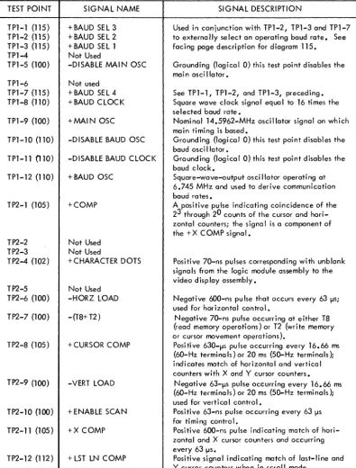
5-1 Logic Module Assembly Test Point Data • • • • • • 5-2
MAINTENANCE
6-1 6-2 6-3 TSl TS2
TS3
TS4
CRTl CRT2 CRT3 NIP1 NIP2 IMP1
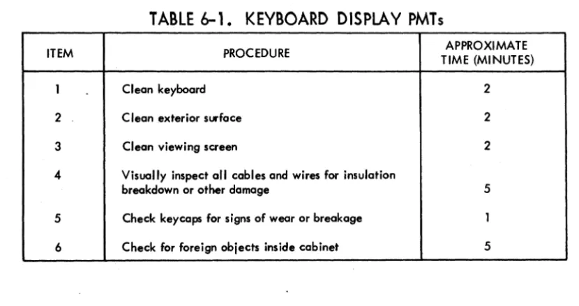
Keyboard Display PMTs •••••••••••••••• Nonimpact Printer PMTs •••••••••••••••• Impact Printer PMTs •••••••••••••••••• DOLT for Terminal Subsystem ••••••••••••• Voltage Level Channel (RS-232-C/CCITT V. 24)
Interface Connector Pin Assignments ••••••• Peripheral Connector Pin Assignments ••••••• Keyboard Interface Signal Lines ••••••••••• DOLT for Keyboard Display ••••••••••.••• DOLT for Keyboard Display •••••••••••••• DOLT for Keyboard Display •••••••••••••• DOLT for Nonimpact Printer ••••••••••••••
Print Quality . . • . . . . • . • . . . • . . .
DOLT for Impact Printer
PARTS DATA
7-1 Explanation of Column Headings on Assembly
6-4 6-5 6-8 6A-1
6A-18 6A-18 6A-19 68-1 68-2 68-3 6C-l 6C-22 60-1
Parts Lists • . • . . . . • • • . • . . . • . . . . • . . . 7-2
GENERAL DESCRIPTION
1
This section describes the general functions, features, and equipment characteristics of the 752 Keyboard Display Terminal and of the two printers that may be associated with the terminal. It includes descriptions of both the basic terminal and its avai 1-able variations.
The basic terminal is a 50- or 60-Hz terminal with an 80-key keyboard and a
modem interface. The user can select 60-Hz versions of the terminal with a current loop interface for connection to a current loop communication facility, or he can select 50-Hz versions with a current loop interface and/or FTZ-approved shielding.* The features incorporated in each type of 752 Keyboard Display Terminal are indi-cated with Xs in table 1-1.
TABLE 1-1. AVAilABLE TERMINAL CONFIGURATIONS
"
--- --- -~
L
TERMINAL TYPE 60Hz 50 Hz CURRENT LOOP FTZ SHIELDING
752-10 X
-
-
-752-11 X
-
X-752-20
-
X-
X752-21
-
X X XU ndes ig noted
-
X-
-Undesignated
-
X X-Additionally, the display terminal is available with either a nonimpact thermal printer or an impact printer. The display terminal and the two different printers are shown in figure 1-1 •
* FTZ (Fernmelde Technisches Zentralamt) is a German licensing agency that sets limits on the radio frequency emissions generated by electrical and electronic devices. Many European countries have adopted FTZ _requirements for the
02201
FUNCTIONS
DISPLAY TERMINAL
NOTE: BROKEN LINES SHOW INTER-CONNECTING CABLE PATHS.
Figure 1-1. Display Terminal Configurations
The display terminal functions as a stand-alone, remote input/output device for a computer system. It performs input and terminal control functions via a detachable keyboard assembly, and it monitors both input and output functions on a 12-inch crt display screen. Included within the display terminal are all of the necessary electronics, including an asynchronous, bit-serial, word-serial, communication facility interface, to permit it to operate in conversational mode in the same
manner as a teletypewriter unit. The display terminal, however, incorporates many features not commonly found in teletypewriter terminals. The addition of one of the available printer peripherals provides the terminal with hardcopy printout capabilities.
FEATURES
The following text highlights six major features of the terminal. These are the display unit, keyboard, operator control, system/terminal interface, nonimpact printer, and impact printer. A features summary list follows the six major features. Other portions of this manual describe many of these fe_atures in greater detai I; this portion of text provides brief descriptions and a features summary to foci I i tate fami I i ari zation and com pari son.
[image:30.619.75.472.72.345.2],
__DISPLAY UNIT
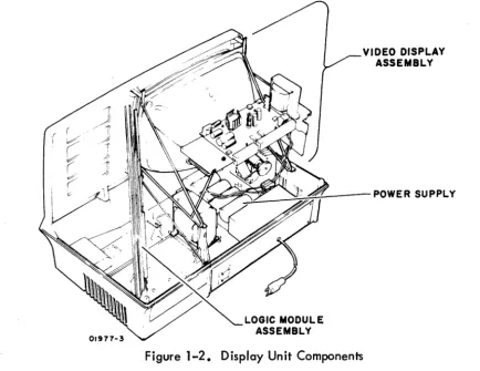
The display unit of the terminal is self-contained and includes a video display assembly, a logic module assembly, and a power supply. The keyboard,
communi-cation line, and printer unit interfaces are part of the logic PC board. The locommuni-cation of major components within the display unit is shown in figure 1-2.
Power Supply
LOGIC MODULE ASSEMBLY
VIDEO DISPLAY ASSEMBLY
Figure 1-2. Display Unit Components
The power supply furnishes all necessary voltages for the display unit from either 115 V ac or 220/240 V ac (nominal), 50- or 60-Hz power input sources.
Video Display Assembly
[image:31.619.85.520.156.491.2]logic Module Assembly
The display recognizes and generates 128 character codes; the 95 alphanumeric character codes recommended by American National Standards Institute (ANSI) standard X3.4-1968, and the 33 control codes recommended by ANSI standard X3.1973. During actual operation, the unit displays all 95 alphanumeric characters and responds to 13 of the 33 control codes as they are received. This leaves 20 control codes for use in specific functions or operations (refer to appendix of this manual for transmit/receive code set). All 128 codes can be transmitted during normal online operation of the terminal.
Character entries onto the display screen occur upon code reception or are made via the keyboard. To ensure entry at the desired screen location, a blinking cursor
underscores the location of the next character entry. During consecutive character entries, the cursor progresses across a display line through all 80 character positions. At character position 73, a beeper signal sounds to warn the operator that the end of a line is approaching. This line-by-line manner of cursor advance continues unti I the last character position of the Jast line is reached. As that character is keyed in, the cursor resets to its home position (upper left corner of display area) or causes the display to scroll; that is, the cursor returns to the beginning of the last line while all lines already entered scroll up one line (the first line is lost as it scrolls off the screen).
Construction of the display unit is modular as indicated in figure 1-2. All circuits are solid-state, and with the exception of some of the power supply and high voltage circuits, all use integrated circuit technology. Both the display unit and the keyboard enclosures are made of heavy-gauge, molded, expanded-plastic, foam material covered with a durable vinyl paint. The overall design of the display unit lends itself to reliability, and the modular construction facilitates maintenance procedures.
KEYBOARD ASSEMBLY
The keyboard assembly, hereafter referred to as keyboard, serves as both a termi na I control and data input unit for the display terminal operator. The terminal control function of the keyboard is discussed briefly in the following portion of this section and more thoroughly in the operation section of the associated Operators Guide/ Reference Manual (see preface). This portion of the text deals principally with the keyboard as a data input unit. The keyboard uses a rna in key c I uster of 67 keys similar in appearance to a standard teletypewriter keyboard. It also has a 13-key numeric-entry cluster, to facilitate making numeric entries, located just to the right of the main key cluster.
1-4 62957400 A
All keycaps are wear-resistant plastic with molded-in characters ta ensure legibility even after long usage, and all have a matte-finish surface to minimize glare. The layout of the keys on the keyboard is shown in figure 1-3.
01499-6
Figure 1-3. Keyboard Layout
The keyboard is a modular unit that attaches to the display unit via an interconnect-ing cable approximately 32 in (813 mm) long. All power required by the keyboard comes from the display unit power supply via this cable, and all data control codes generated by the keyboard are passed on to the logic circuits of the display unit via this same cable.
The keyboard features trilevel operation; that is, it operates in lowercase mode, uppercase mode (SHIFT key actuated), and in control mode (CONTROL and char-acter keys actuated; or SHIFT, CONTROL, and charchar-acter keys actuated). In this manner, the keyboard can be used to generate a full 128-character,
ANSI-compatible code set. The complete character and code sets used in the display terminal are included in the appendix of this manual.
OPERATOR CONTROLS
The display terminal has operator controls located on the keyboard and on the front and rear panels of the display unit. The controls most commonly used by the operator during display terminal operation are located on the keyboard assembly. Following is a list of these keyboard controls; their functions are described more thoroughly in the associated Operators Guide/Reference Manual (see preface).
• CO indicator - on terminals having a voltage level interface, this indicator lights to indicate the data set (modem) is ready and a carrier frequency signal is being received from the distant station.
• ODD PAR/NO/EVEN PAR switch - selects odd, even, or no parity check/generate functions of the terminal.
• FULLDUP/HALF DUP switch - directs transmit data to either the communication interface only (FULL DUP) or to both the communication interface and the display/printer interface.
• ON LINE/LOCAL switch - selects online or offline mode of display term ina I operation.
• HIGH RA TE/300/LOW RATE switch - selects transmit/receive baud rate for the term ina I.
• 96/64 switch
transmission. selects 96- or 64- character code set for data • PAGE switch - selects page or scroll mode of display operation.
Just to the right of the display screen on the front panel is a single control knob. This is the INTENSITY control knob, used to adjust the intensity of the crt display to suit ambient lighting conditions in the area of display terminal installation.
The display terminal rear panel, shown in figure 1-4, has the data set and peripheral connectors, a test switch, the ac power cord, and circuit breaker CB1. CB1 serves as the terminal on/off switch, and is used to apply or remove ac power to the ter-minal. The test switch is for use when testing or checking display term ina I operation.
~
0 0 0
PRIMARY CIRCUIT BREAKER COUP CIRCUIT PRIMAIRE TO AVOID ELECTRIC SHOCK,
0
DISCONNECT EQUIPMENT FROM POWER®
~. ~---
..?jj]<§)
SOURCE BEFORE SERVICING
@
® AFIN D'EVITER TOUT DANGER, DEBRANCHEZ L.'EQUIPEMENT PERIPHERAL CONNECTOR TEST
AVANT DE REPARER
ii
CBI®\Fg;gj]®
~
0
NORMAL
0 DATA SET CONNECTOR G) 0 0
02143
Figure 1-4. Display Terminal Rear Panel
SYSTEM/DISPLAY TERMINAL INTERFACE
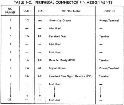
The display terminal has two interface connectors on the rear panel. The PERIPHERAL CONNECTOR is used to connect either the impact printer or the nonimpact printer to the terminal. The DATA SET CONNECTOR is used to connect the terminal to the communication facility. Connector pin assignments for the peripheral connector are shown in table 1-2. Pin assignments for the data set connector vary with the type of communication facility being interfaced, either current loop or voltage
level. Pin assignments for voltage level channel connections are shown in table 1-3. Pin assignments for current loop channe Is are much simpler and are described a
little later in this portion of the text.
The printer interface is compatible with RS-232-C and CCITT V .24 recommendations for full- or half-duplex, asynchronous communication facilities. The purpose of the printer interface is to enable hardcopy records of communications to be produced via a peripheral printer. In a manner similar to the display, only received informa-tion is routed to the printer during full-duplex, online operainforma-tion of the terminal; while both received and transmitted information is routed to the printer during half-duplex, online operation. Both the printer and the communication channel baud rate selectors must be set for the same transfer rates.
TABLE 1-2. PERIPHERAL CONNECTOR PIN ASSIGNMENTS
PIN CCITT EIA SIGNAL NAME
NUMBER ORIGIN
I 101 AA Protective Ground Printer/Terminal
2
-
-
Not Used-3 104 BB Received Data Terminal
4
-
-
Not Used-5
-
-
Not Used-6 107
cc
Data Set Ready (DSR) Terminal·.
7 102 AB Signal Ground Printer/Terminal
8 109 CF Received Line Signal Detector (CO) Terminal
9
-
-
Not Used-j
j
J
J
J
[image:35.615.107.512.366.706.2]-1-8
PIN NUMBER
1 2 3 4 5 6 7 8 9 10 11 12 13 14 15 16 17 18 19 20 21 22 23 24 25
TABLE 1-3. VOLTAGE LEVEL CHANNEL INTERFACE
CONNECTOR PIN ASSIGNMENTS
CCITT EIA SIGNAL NAME ORIGIN
101 AA Protective Ground Modem/Terminal 103 BA Transmitted Data Terminal
104 BB Received Data Modem
105 CA Request ta Send (RTS) Terminal 106 CB Clear to Send (CTS) Modem 107
cc
Data Set Ready (DSR) Modem102 AB Signal Ground Modem/Terminal 109 CF Received Line Signal Detector (CO) Modem
-
-
Not Used--
-
Not Used--
-
Secondary Request to Send (SRTS)*-122 SCF Secondary Received Line Signal Detector (SCO) Not Used 121 SCB Secondary Clear to Send (SCTS) Not Used 118 SBA Secondary Transmitted Data Not Used 114 DB Transmission Signal Element Timing Not Used 119 SBB Secondary Received Data Not Used 115 DO Receiver Signal Element Timing Not Used
-
-
Not Used-120 SCA Secondary Request to Send (SRTS) Terminal 108.2 CD Data Terminal Ready (DTR) Terminal 110 CG Signal Quality Detector Not Used 125 CE Ring Indicator Not Used 111 CH Data Signal Rate Selector Terminal 113 DA Transmit Signal Element Timing Not Used
-
-
Not Used-* Data set connector has pin 11 jumpered to pin 19.
62957400A
J
In local mode operation of the display terminal, keyed-in data is directed to both the display screen and to the peripheral printer, regardless of the setting of the half-duplex/full-duplex switch. Selection of local mode always disconnects the transmit interface of the display terminal, while the receive interface may be either maintained or disabled via switch conditioning within the terminal; see CONSTANT DTR Switch description in the associated Operators Guide/Reference Manua I (see preface) or refer to section 5 of this manua I.
The rear panel data set connector is used to interface voltage level terminals to a voltage level communication facility, and current loop terminals to a current loop communication foci lity. As indicated in table 1-3, terminals interfacing voltage level communication facilities use RS-232-C/CCITT V .24-compatible signals to
and from the data set connector. Current loop terminals use receive and transmit circuits designed to interface a 20-milliampere current loop communication facility. The data set connector pins used on current loop terminals vary with the type of current loop facility being connected. Unipolar, half-duplex facilities use pin 2 for transmit data and pin 3 for receive data; unipolar, full-duplex facilities use pin 2 for transmit data, pin 3 for receive data, and pin 7 as a common receive/ transmit channel ground.* Although all current loop terminals use the same trans-mit and receive circuits, internal conditioning of terminals used on a half-duplex current loop facility differs slightly from that of terminals used on a full-duplex current loop facility (refer to facing-page description for Current loop Transmit and Receive Diagram in section 5).
With the exception of their different communication facility interfaces, voltage level and current loop terminals operate in an identical manner.
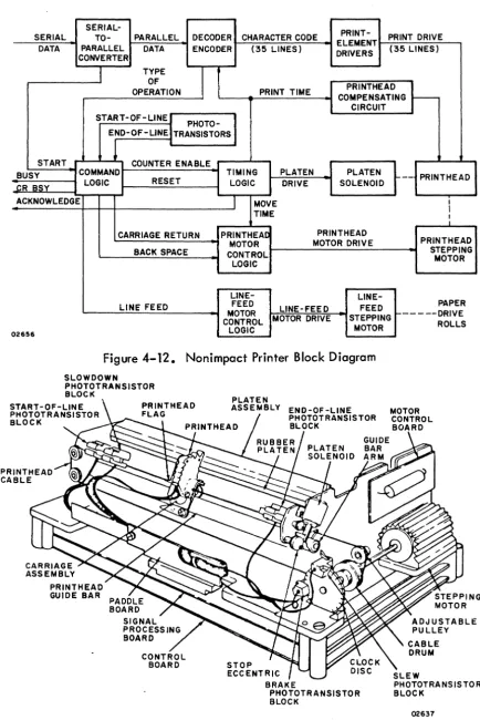
NONIMPACT PRINTER
The nonimpact printer, see figure 1-5, operates as an output peripheral device in conjunction with the display terminal. It prints a maximum of 30 characters per
second (300 baud) in serial order, and checks for even character parity. A full print line is 80 characters maximum.
The printer cabinet contains the following major functional components; a print mechanism, interface and control logic cards, and a power supply. The position of these components within the printer cabinet is shown in figure 1-6.
CONTROL LOGIC CARD
1-10
Figure 1-5. N . on1mpact p. rmter
., .. j
02203
Figure 1-6. N on•mpact . p. rmter C omponents
Print Mechanism
The print mechanism consists of the electromechanical elements necessary to print
characters and to advance the roll-type heat-sensitive paper on which characters are printed. Printing is done by a single printhead that consists of a set of heater elements arranged in a 5- by 7-dot matrix. A character is printed by bringing the printhead into contact with the heat-sensitive paper and quickly heating the matrix elements necessary to reproduce the desired character. Multi copy records cannot be made on this type of printer. The printer is capable of reproducing the 95
(including space) uppercase and lowercase characters and symbols listed in appendix A of this manual. It responds to the following ASCII control codes: backspace, line feed, and carriage return.
Interface and Control Logic Cards
The interface and control logic cards contain circuits for interfacing the printer to the display terminal and for controlling printer operation. The interface card
accepts serial outputs from the display terminal, assembles and decodes these outputs, and directs them to the appropriate circuits (data outputs to the printhead and con-trol outputs to the concon-trol logic). The concon-trol card provides timing and concon-trol signals for all printer operations.
Power Supply
The nonimpact printer power supply is a single, removable assembly that provides four regulated de voltages: +5 for all logic circuits, + 16 for the print mechanism, +24 for the print mechanism, and -24 for the printer/terminal interface circuits. All outputs have over current and overvoltage protection.
IMPACT PRINTER
The impact printer, shown in figure 1-7, operates as a peripheral device for the display terminal in lieu of the nonimpact printer. It prints characters in serial order at speeds of up to 173 characters per second in a 60-Hz version or 180 char-acters per second in a 50-Hz version. It includes internal switches for selecting
150, 300, 600, or 1200 baud data reception rates and for selecting either odd or even parity checking of received codes. Although the impact printer has a print line capacity of 132 characters, the use of line feed and carriage return control codes can format a print line to match the display line format of 80 characters.
1-12
PRINTHEAD DRIVER BOARD
I pact Printer Figure
1-7.
mFigure 1-8. lmpac t Printer C 0 mponents
02202