5
II
February 2017
Technology (IJRASET)
High Efficiency Intelligent Street Lighting System
Using a Zigbee Network and GSM
Moeenuddin Md. Mohsin1, Ishwar S. Jadhav 2, V. D Chaudhari3 1PG Research scholar, 2,3Assistant professor
Departments of Electronics and Telecommunication, GF’s Godavari College of Engineering, Jalgaon, North Maharashtra University
Abstract: The proposed street lighting system is highly energy efficient and automated. It uses ZigBee-based wireless devices due to which street lamp system becomes more efficient. ZigBee network is connected to GSM through computer which is located in base station. Sensor combination is used to control and guarantee the desired system parameters. The information is transferred to a control terminal using ZigBee network which is used to check the prominence of the street light. Appropriate action is taken whenever system fails, by observing the status of street light.
On the basis of the plan an automatic energy saving system for street lighting using ZigBee network is developed and tested. Keywords: control terminal, street lighting system, ZigBee network, GSM
I. INTRODUCTION
In the present world generally street lighting system belongs to public sector. This consumes 20% of the total power and also it will contain many hurdles in the maintenance such as changing the damaged one’s and also has to check weather all the lights are in working situation or not and switching on and off daily at particular times and also cost factor is very high. At present many technologies developed in all fields but the street light system is designed and developed on old methods so to improve the standards of street light system so in this paper it is tried to implement recent technologies in this field. And most of the companies are showing much importance to latest technologies by considering some of the factors such as safety of the pedestrians and night travellers and so on. In the existing system by making small changes there are many options to develop street light system according to our present day life without wasting time, power and money. The first and foremost opportunity is replacing the existing lamp with the LED(Light Emitting Diode) lamp which consumes less power and consistency time is very high when compared with other lamps. The second probability is to replace the power supply from power lines to solar energy which is available at free of cost. The third probability is adding some extra circuitry which consists of sensors such as presence sensor, emergency device, working sensor, light sensor. By which the maintenance of the system become less complex when compared with old method.
A. Objectives
In this system two street lamps are established and termed as monitoring station-1 and monitoring station-2. Practically as many as monitoring station can be designed. Each monitoring station consists of microcontroller, Zigbee, LCD, relay and different sensors. The three dedicated sensors which are LDR works for determining the information of day and night, PIR ensors which helps to detect the information of occurrence of human. Current Sensor is to measure the flow of current in the lamp load. These sensors continuously monitor the street lamps condition.
II. METHODOLOGY
Proposed methodology is divided into three parts. They are as follows: Sensing System
Communication System Control System
Technology (IJRASET)
Control system consists of microcontroller PIC16F877A for taking the desired action according to the sensor data of respective monitoring station.
A. Proposed model
Monitoring stations are consist of microcontroller which is used to transfer the current status of a lamp to a control station through Zigbee module and operate the lamp according to a command send from the control station with the help of relay.
The control station consists of microcontroller which is used to transfer the command received from the GSM module to a respective monitoring station through Zigbee module. It also consists of PC which stores the data base and controls the lamp through GUI via Zigbee module.
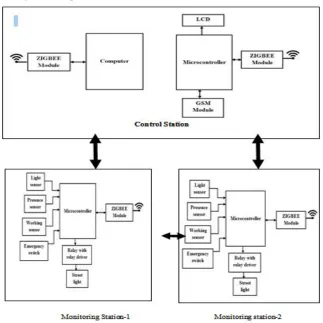
Figure 1 shows the block diagram of the proposed system. Each measuring system placed on the lamp monitors the street conditions like light intensity, presence of human being, depending on these parameters they decide to turn the lights “ON” or “OFF”. The system also checks whether the lamp is working or not and sends the information through a wireless network to a control station. If any malfunction is detected.
Here a GSM modem is connected to the microcontroller in control station. In case of light sensor fails to turn off the lamp during the day time one can send the SMS to turn off that lamp. After sending, the message will be received by the GSM modem connected to microcontroller, the command will be sent from microcontroller through Zigbee to respective monitoring station to turn ON/OFF the lamp.
Each lamp post consists of several modules such as presence sensor, light sensor, Current sensor, and an emergency switch. These devices work together and transfer all of the information to a microcontroller which processes the data and automatically sets the appropriate course of action. A priority in the transmission of information is allocated to each sensor for example, the emergency switch takes precedence over any other lamp device.
[image:3.612.145.468.352.675.2]
Figure 1 Block diagram of the proposed system
B. Presence Sensor
Technology (IJRASET)
lamps. This function depends on the pattern of the street; in case of a street without cross-roads, a single sensor is enough (or one at each end in case of a two-way street), while for a street requiring more precise control, a solution with multiple presence detectors is necessary.
This feature allows switching on the lamps only when necessary, avoiding a waste of energy. The main challenge with such a sensor is its correct placement. The sensor should be placed at an optimum height, not too low (i.e., to avoid any erroneous detection of small animals) nor too high (for example, to avoid failure to detect children). A study of the sensor placement enables deciding the optimal height according to the user needs and considering the specific environment in which the system will work.
C. Light Sensor
A light sensor can measure the illumination of the sunlight and provides information. The purpose of this measurement in this system is to check the day light to keep the street light OFF during a day and to turn ON the light in night.
D. Current Sensor
This sensor is useful to improve faultmanagement and system maintenance. It is possible to recognize when the lamp is switched
on. The system is able to identify false positives, because identified parameters are compared with the stored data (e.g., lamps are switched off during daylight and the sensor incorrectly senses a fault, but the microcontroller does not report the malfunction because of additional logic functions). The information is reported through the Zigbee network to the station control unit, where the operator is informed about the location of the break-down lamp and can send a technician to replace it. The system current is 1.5 A, so a sensor suited to detect this current is necessary. An suitable threshold value to detect the operation of the lamp has been set between 1 and 1.5 A. The chosen sensor is the ACS712 of the Allegro Microsystems, an economical and accurate solution for AC or DC current sensing, particularly suitable for communication systems. It is possible to store in the microcontroller’s memory the current value which flows in the LED lamp in ordinary operating conditions, enabling the online power consumption measurement.
E. Emergency Switch
The system has an emergency button, which can be useful in case of an emergency. This device excludes the entire sensor system
with the objective to immediately turn on the lamp. The light will remain on for a stipulated time. After that, the button must be pressed again. This prevents the system from being accidentally active even when the necessity ends.
F. GSM Control Unit
The SMS sent from a person or operator will turn ON or OFF the street light if the system having any problem with Zigbee network. It will direct the node-1, node-2, and monitoring station to change the status of street lamp.
III. RESULT AND ANALYSIS
[image:4.612.125.487.538.715.2]The possible contribution of the system is use to reduce the power consumption of a street light. It is a humble approach to diagnose the street light running conditions with an intelligent program within a microcontroller based dedicated system.
Technology (IJRASET)
[image:5.612.103.510.114.401.2]the uniqueness of the proposed system is that the abnormal running conditions of street light installed at different locations are detected, diagnosed and reported to control station. Also the street light can be control through a mobile
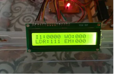
Figure 3 Control Station GSM
This system minimizes the consumption of electricity and contributes for saving the energy. This system will increase flexibility, cost effectiveness and will be small in size in terms of product. This system will consume less power and will reduce complexity.
[image:5.612.106.509.451.711.2]Technology (IJRASET)
A. Comparison of Normal and proposed system
Different types of load were used for testing the system, some of them are describe below.
FTL = Fluorescent Tubular Lamp, HPSVL = High Pressure Sodium Vapor Lamp, MVL = Mercury Vapor Lamp.
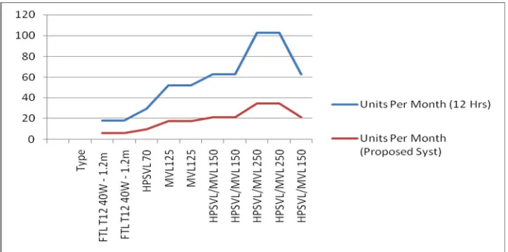
In normal system the lamp is continuously ON for 12 hours but in the proposed system the experimented values considering the lamp was ON for four hours which can be changed showing various factors like season, fog, or might be the frequency of vehicles or persons.
From the below table one can predict that the traditional street lights having various types of bulbs in which FTL T12 40W - 1.2m were consuming 18 units per month was reduced to 6 units per month so saving of 12 units is observed, which means the saving is 66.66%.
In another case the street lamps currently installed in few district of Maharashtra in which by considering FTL T5 28W - 1.2m is consuming 10.08 units per month where as by applying this project then in that case the total time of four hours if it is ON then it will consume 3.36 units per month which means the saving of 66.67% of energy.
[image:6.612.126.488.527.707.2]The total power consumption in x hours is calculated as (Rating*x/1000) (kWh). The total power consumption in a month is calculated as (total power consumption in 1 day*30).The billing amount is considered as per Municipal Corporation Areas Energy Charge (Rs. /kWh) of Maharashtra state electricity distribution co. ltd. as Rs 5.80/-.
Table 1
Comparison of normal and proposed system
Type Rating
(W)
NORMAL SYSTEM PROPOSED SYSTEM
UNITS SAVED UNITS FOR 12 HOURS UNITS PER MONTH COST PER MONTH (RS) UNITS FOR 4 HOURS UNITS PER MONTH COST PER MONTH (RS) FTL T12
40W-1.2m 50 0.6 18 104.4 0.2 6 34.8 12
HPSVL 70 82 0.984 29.52 171.216 0.328 9.84 57.072 19.68
MVL125 145 1.74 52.2 302.76 0.58 17.4 100.92 34.8
HPSVL/MV
L 150 175 2.1 63 365.4 0.7 21 121.8 42
HPSVL/MV
L 250 285 3.42 102.6 595.08 1.14 34.2 198.36 68.4
FTL = Fluorescent Tubular Lamp, HPSVL = High Pressure Sodium Vapor Lamp, MVL = Mercury Vapor Lamp, Low Pressure Mercury Fluorescent Tubular Lamp (T12 &T8), Energy-efficient Fluorescent Tubular Lamp (T5), Light Emitting Diode (LED) [6]
Technology (IJRASET)
[image:7.612.180.432.87.281.2]B. Graphical Output
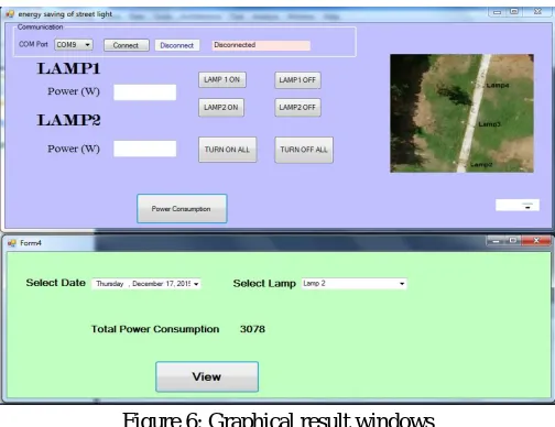
Figure 6: Graphical result windows
The GUI shows the status of two Lamps power consumption, it also provide the respective control buttons to turned ON & OFF the lamps. It maintains the day wise data base of power consumption of each lamp as well as total power consumption for the future reference.
IV. CONCLUSION
This system provides an efficient and smart automatic control system with the Zigbee technology. The system can reduce energy consumption and maintenance costs and also helps to reduce crime activities up to certain limit. This streetlight control system helps in energy savings, detection of defective lights and maintenance time and increase in life span of system.
Another advantage obtained by the control system is the intelligent management of the lamp posts by sending information to a central station by Zigbee wireless communication. The system maintenance can be easily and efficiently planned from the central station, allowing additional savings.
The proposed system is particularly appropriate for street lighting in urban and rural areas where the traffic is low at a given range of time. The independent nature of the power supply network enables realizing the system in remote areas where the classical installations are prohibitively expensive. The system is always flexible, extendable, and fully adjustable to user needs. The simplicity of Zigbee, the reliability of electronic components, the feature of the sensor network, the processing speed, the reduced costs, and the ease of installation are the features that characterize the proposed system.
REFERENCES [1] Budget connect +2015 “ Government of India full budget 2015”.
[2] World Bank, Energy Sector Management Assistance Program (ESMAP). 2009. Energy Efficient Cities Initiative. Good Practices in City Energy Efficiency: Akola Municipal Corporation, India - Performance Contracting for Street Lighting Energy Efficiency. Washington DC, USA.
[3] Republic of India Energy-Efficient Urban Street Lighting India: “Energy-Efficient Street Lighting-Implementation and Financing Solutions” June 2015. [4] Maharashtra State Electricity Distribution Co. Ltd. “Approved Tariff Schedule” (with effect from June 1, 2015) Multi Year Tariff Order dated 26 June, 2015 in
Case No. 121 of 2014.
[5] “Energy-efficient Street Lighting guidelines” version2.0, June 2010.
[6] Satwinder Singh , Suman Bhullar “Automatic Street Lighting System uses NE555 Integrated Circuit and LDR” Journal of The International Association of Advanced Technology and Science, volume 16 , Jan2015.
[7] Alissa Johnson, Amol Phadke, Stephane de la Rue du Can,“Energy Savings Potential for Street Lighting in India February 2014” Ernest Orlando Lawrence Berkeley National Laboratory.
[8] D. Gislason, “Product Manual v1.xAx – 802.15.4 Protocol for OEM RF Module Part Numbers: XB24001, IEEE 802.15.4 OEM RF Modules by Maxstream,” Zigbee Wireless Networking, 1st ed. Burlington, MA: Newness, 2008. Maxstream, Inc., London, UT, 2007.
[9] W. Yongqing, H. Chuncheng, Z. Suoliang, H. Yali, and W. Hong, “Design of solar LED street lamp automatic control circuit,” in Proc. Int. Conf. Energy Environment Technol., Oct. 16–18, 2009, vol. 1, pp. 90–93.
[10] M. A. D. Costa, G. H. Costa, A. S. dos Santos, L. Schuch, and J. R. Pinheiro, “A high efficiency autonomous street lighting system based on solar energy and LEDs,” in Proc. Power Electron. Conf., Brazil, Oct. 1, 2009, pp. 265–273
[11] P.-Y. Chen, Y.-H. Liu, Y.-T. Yau, and H.-C. Lee, “Development of an energy efficient street light driving system,” in Proc. IEEE Int. Conf. Sustain. Energy Technol., Nov. 24–27, 2008, pp. 761–764.
Technology (IJRASET)
power delivery, vol. 28, no. 1, January 2013, pp. 21-28.[13] W. Yue, S. Changhong, Z. Xianghong, and Y. Wei, “Design of new intelligent street light control system,” in Proc. 8th IEEE Int. Conf. Control Autom., Jun. 9–11, 2010, pp. 1423–1427.
[14] Akola Municipal Corporation, “Good Practices In City Energy Efficiency: India - Performance Contracting for Street Lighting Energy Efficiency”.
[15] Y. Chen and Z. Liu, “Distributed intelligent city street lamp monitoring and control system based on wireless communication chip nRF401,” in Proc. Int. Conf. Netw. Security, Wireless Commun. Trusted Comput. Apr. 25–26, 2009, vol. 2, pp. 278–281.