Technology (IJRASET)
Area and Power Efficient MSIC Test Pattern
Generation for BIST
M.Nandini Priya1,Dr. (Mrs.) R.Brindha2 1
P.G.Scholar /II M.E VLSI Design, 2Professor and Head of the Department,
Dept of Electronics and Communication Engineering,
Avinashilingam Institute for Home Science and Higher Education for Women-University,Coimbatore, India
Abstract-This paper proposes a technique to generate the multiple test patterns varying in single bit position for built-in-self-test (BIST). The conventional built-in-self-test patterns generated using LFSR have an absence of correlation between consecutive built-in-self-test vectors. So, in order to improve correlation between the subsequent test vectors, test patterns were produced using binary to thermometer code converter. The methodology for producing the test vectors for BIST is coded using VHDL and simulations were performed with ModelSim 10.0b. 100% fault coverage is achieved with less number of test patterns. The Area utilization, power and delay report were obtained with Xilinx ISE 9.1 software. The area reduction of 62%, power reduction of 13% is achieved while generating test patterns using binary to thermometer code converter when compared with the patterns generated using Reconfigurable Johnson counter and LFSR.
Keywords-Built-in-self-test (BIST), Test Pattern Generator (TPG), Multiple Single Input Change Vector (MSIC), Linear feedback shift registers (LFSR), Thermometric code.
I. INTRODUCTION
Technology (IJRASET)
II. EXISTING METHODOLOGY
The Existing technique generates the test pattern using Johnson counter and the seed vector. Reconfigurable Johnson counter generates the Johnson vector and Linear Feedback Shift Registers generate seed vector. Test patterns were generated by performing Exclusive-or operations between Johnson counter and seed vector [14]. The vectors obtained were applied to the scan chain.
A. Generating Test Vectors
Fig.1 MSIC pattern generation [14]
Let us consider m primary inputs, M scan chains and l scan cells. Fig.1 shows pattern generation technique for BIST. The seed vector is produced using LFSR with the primitive polynomial, and the Johnson vector is produced using 8-bit Johnson counter. During the first clock cycle, the Exclusive-or operation is performed between Johnson vector and seed vector and the results obtained were applied to the first scan cell in the scan chain. For the next clock cycle the toggled result corresponding to former flip flop is feedback as an input. The Exclusive-or operation is performed between the Johnson vector generated in second clock cycleand seed vector generated using primitive polynomial. The result corresponding to the second clock cycle was applied to the second scan cell in the scan chain. The procedure is repeated by performing the Exclusive-or operation between Johnson vectors and Seed vectors until the required test length is obtained.
B. Reconfigurable Johnson Counter
Reconfigurable Johnson counter is utilized to produce the Johnson vectors. In case of Johnson counter, the toggled result corresponding to former flip flop is fedback and Reconfigurable Johnson counter operates in three modes.
1)Initialization: Reconfigurable Johnson counter is initialized by setting the value of RJ_Mode to 1 and Init to 0. The CLK2 is
clocked until the flip flops are initialized to a known value.
2)Circular Mode: The circular shift operation can be performed by assigning the values of Init and RJ_mode to 1.
3) Normal Mode: The select input of the multiplexer RJ_MODE is assigned to the value 0. The Q8 output corresponding to D8
flip flop is fedback.
Fig.2 Reconfigurable Johnson counters [14]
Clock RJ_mode
J1 J2
Init
D1Q1
D1
D2Q2
D2
D8Q8
D8 Q8
Technology (IJRASET)
III. PROPOSED METHODOLOGY
Area, Delay and Power are the challenging parameters in VLSI. The need for the portable devices is increasing rapidly. In order to have better optimization, the patterns were generated using binary to thermometer code converter. The produced patterns were tested on the circuit under test. The response obtained is compared with the known result to verify the correctness of the circuit. The test patterns generated were applied on multiplier circuit. The exact functioning of the circuit is verified by comparing with the known result. The patterns produced have the ability to detect the faults in a combinational circuit. The circuits are designed to generate the test patterns with less number of toggles between successive bits. The subsequent test transitions between the successive vectors were curtailed to minimize the power requirements.
A. Binary To Thermometer Code Converter
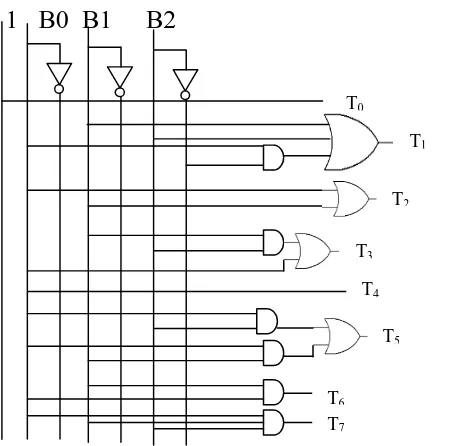
[image:4.612.236.349.281.439.2]The test patterns were generated using binary to thermometer code converter to have reduced number of transitions with minimum gate count. The block diagram of binary to thermometer code converter is as shown in Fig.3. Three bit binary up down counter is used. The results of binary counter are converted into thermometer code using binary to thermometer code converter. The eight bit results produced from binary to thermometer code converter were tested on multiplier circuits. Fig. 4 indicates the logic diagram corresponding to binary to thermometer code converter.
Fig.3 Block Diagram of Binary to thermometer code converter
Fig. 4 Logic diagram of binary to thermometer code converter Binary Counter
Binary to Thermometer
Code Converter
Test Patterns
T0
1 B0 B1 B2
T1
T2
T3
T4
T5
T6
[image:4.612.228.454.460.683.2]Technology (IJRASET)
IV. SIMULATION RESULTS AND ANALYSIS
The test pattern generation for BIST is implemented using front end ModelSim 10.0b software and Xilinx ISE 9.1 software. The design is coded in VHDL and simulations were performed using ModelSim 10.0b software. The test patterns generated were tested on 4*4 Multiplier circuit. The analysis of area, delay and power are performed using Xilinx ISE 9.1 software.
A. Binary To Thermometer Code Converter
[image:5.612.151.460.190.297.2]The result of binary to thermometer code converter is as shown in the Fig. 5. For each binary value, corresponding thermometer code is generated.
Fig. 5 Binary to thermometer code converter
B. Testing Of Multiplier Using Binary To Thermometer Code Converter
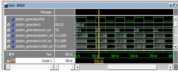
The simulation result for testing multiplier circuit by applying test patterns generated using binary to thermometer code converter is shown in the Fig.6. count_out is the required test pattern. The output signal ref_out is the expected result and test_out is the output after injecting the test patterns. Here v is assigned with value “000110” indicating s-a-0 fault at fourth input bit of multiplier. When the vectors of ref_out and test_out are equal, then the pattern is incapable of detecting the fault at that position. Here the pattern “11111000” is applied on the multiplier circuit and the expected result of the multiplier circuit ref_out is “01111000”. But the result obtained after injecting s-a-1 fault at fourth input bit of multiplier circuit, test_out is “01110000”. The results of ref_out and test_out obtained by applying the pattern “11111000” are different. Hence the pattern “11111000” is capable of detecting s-a-0 fault at fourth input bit of multiplier.
Fig. 6 Testing of Multiplier usingbinary to thermometer code converter
C. Analysis Report
[image:5.612.169.468.458.579.2]Technology (IJRASET)
[image:6.612.208.436.133.302.2]using reconfigurable Johnson counter and binary to thermometer code converter is shown in Fig.4.
TABLE 1
COMPARISON TABLE
V. CONCLUSION
The test pattern generation for BIST to attain 100% fault coverage using binary to thermometer code converter is proposed. Three bit up down counter and binary to thermometer code converter have been developed to generate the test patterns with optimized area, delay, power and test length. The single input change patterns generated to improve the correlation between the successive test patterns reduce power requirements. This technique to generate the multiple test patterns varying in single bit position for BIST schemes is coded using VHDL and simulated using ModelSim 10.0b. The gate count and power consumption of the test pattern generation were analyzed using Xilinx ISE 9.1 software. Area reduction of 62%, delay reduction of 75%, power reduction of 13% and test length reduction of 33% are achieved while generating test patterns using proposed binary to thermometer code converter.
REFERENCES
[1] Y. Zorian, ‘A distributed BIST control scheme for complex VLSI devices,’ in 11th Annual IEEE VLSI Test Symposium, April 1993, pages 4–9. [2] P. Girard, ‘Survey of low-power testing of VLSI circuits,’ IEEE Design & Test of Computer, volume 19, number 3, pages 80–90, May–June 2002. [3] A. Abu-Issa and S. Quigley, ‘Bit-swapping LFSR and scan-chain ordering: A novel technique for peak- and average-power reduction in scan-based BIST,’ IEEE Transaction Computer-Aided Design Integrated Circuits System, volume 28, number 5, pages 755–759, May 2009.
[4] P. Girard, L. Guiller, C. Landrault, S. Pravossoudovitch, J. Figueras, S. Manich, P. Teixeira, and M. Santos, ‘Low-energy BIST design: Impact of the LFSR TPG parameters on the weighted switching activity,’ in Proceedings of IEEE International Symposium of Circuits and Systems, volume 1, July 1999, pages 110–113.
[5] S. Wang and S. Gupta, ‘DS-LFSR: A BIST TPG for low switching activity,’ IEEE Transaction on Computer-Aided Design of Integrated Circuits and Systems, volume 21, number 7, pages 842–851, July 2002.
[6] F. Corno, M. Rebaudengo, M. Reorda, G. Squillero, and M. Violante, ‘Low power BIST via non -linear hybrid cellular automata,’ in Proceedings of 18th IEEE VLSI Test Symposium, April –May 2000, pages 29–34.
[7] P. Girard, L. Guiller, C. Landrault, S. Pravossoudovitch, and H. Wunderlich, ‘A modified clock scheme for a low power BIST test pattern generator,’ in Proceedings of 19th IEEE VTS VLSI Test Symposium, March–April 2001, pages 306–311.
[8] D. Gizopoulos, N. Krantitis, A. Paschalis, M. Psarakis, and Y. Zorian, ‘Low power/energy BIST scheme for datapaths,’ in Proceedings of 18th IEEE VLSI Test Symposium, April–May 2000, pages 23–28.
[9] Y. Bonhomme, P. Girard, L. Guiller, C. Landrault, and S. Pravossoudovitch, ‘A gated clock scheme for low power scan testing of logic ICs or embedded cores,’ in Proceedings of 10th Asian Test Symposium, November 2001, pages 253–258.
[10] C. Laoudias and D. Nikolos, ‘A new test pattern generator for high defect coverage in a BIST environment,’ in Proceedings of 14th ACM Great Lakes Symposium VLSI, April 2004, pages 417–420.
[11] S. Bhunia, H. Mahmoodi, D. Ghosh, S. Mukhopadhyay, and K. Roy, ‘Low-power scan design using first-level supply gating,’ IEEE Transaction Very Large Scale Integrated (VLSI) Systems, volume 13, number 3, pages 384–395, Mar. 2005.
[12] X. Kavousianos, D. Bakalis, and D. Nikolos, ‘Efficient partial scan cell gating for low-power scan-based testing,’ ACM Transaction on Design Automation Electronic Systems, volume 14, number 2, pages 28-1–28-15, Mar. 2009.
[13] M.Nandini Priya, ‘Area reduction of test pattern generation used in BIST schemes’ , in the International Journal of Engineering Trends and Technology, volume 9 number 13-March 2014.
[14] Feng Liang, Luwen Zhang,scaochong Lei, Guohe Zhang, Kaile Gao and Bin Liang, ‘Test patterns of Multiple SIC Vectors: Theory and Application in BIST Schemes’, IEEE Transactions on Very Large Scale Integration (VLSI) Systems, Volume 21, Number 4, April 2013.
[15] Nandini Priya.M and Dr.R.Brindha, ‘An Enhanced Architecture for high performance BIST TPG’, in International conference on Innovations in Information, Embedded and communication systems, Volume 3, pages 686-691.
Reconfigurable Johnson counter & LFSR[14] Binary to Thermometer Code Converter Area
( Gate count)
312 120
Power (mW)
41.79 36.35
Test length
12 8
Delay (ns)