Technology (IJRASET)
©IJRASET: All Rights are Reserved
34
Design and implementation of
FPGA control unit
for solar
Application
V.Sahana1, Dr.M.Jagadeeswari2
M.E VLSI Design, Professor & Head, ECE (PG - VLSI Design) Sri Ramakrishna Engineering College, Coimbatore, India
Abstract: Designing photovoltaic systems to maximize the output power Maximum Power Point Tracking (MPPT) is used. The new MPPT system is developed, using DC-DC converter. The design of FPGA control unit which includes the power circuit and a MPPT circuit with a buck boost circuit. The voltage divider circuit is used to send the constant voltage to the battery from the solar input. The ADC is used to convert the input analog signal from the solar panel to digital signal. Pulse width modulation technique is employed in this paper to give low total harmonic distortion with output voltage and frequency control. The qualitative performance parameters of the PWM technique are mathematically analyzed. The result shows that the voltage supply will be constant to the battery. The PWM is coded in VHDL and the design has been implemented in ALTERA CYCLONE board which requires 25mA for the start of execution. The board is powered by 12V DC supply by using a step down transformer.
Keywords: Maximum Power Point Tracking (MPPT), Analog to Digital Converter (ADC), Field Programmable Gate Array (FPGA), Pulse Width Modulation (PWM), Very High Speed Integrated Circuit Hardware DescriptionLanguage.
I. INTRODUCTION
Renewable energy research has come into existence due to the usage of fossil fuels and to meet the environmental impacts and the energy demands. Among the renewable energy sources solar energy has become a promising energy source for widespread utilization. Hence Solar systems have been deployed widely due to its abundance and accessibility.
According to [1], in 2011, the photovoltaic (PV) industry had added estimated 17 GW capacities. Worldwide bringing the global capacity to about 40 GW. The annual growth rate for capacity of solar PV has been around 50% since 2005, which is the fastest growth of all renewable energy sources. PV arrays, which converts solar energy to electrical energy. When connecting solar panels to the load, there is a probable mismatch between the load current and voltage characteristics and the MPP. Thus, tracking of MPP is very important not only to improve the system’s efficiency but also to reduce the requirement of solar panels for the desired output power [2]. Maximum power point tracking (MPPT) technology has become a very popular research topic in the past two decades [3]. In [3], more than a dozen of different MPPT methods are introduced.
There are two charging stages for the PV charger. A continuous MPPT-charging scheme is adopted at the beginning of the charging process. To obtain an average charging current with an exponential profile a pulse-current-charging scheme with an adaptive rest period is applied when the battery reaches a given condition. The MPPT function is retained to achieve high charging efficiency during the charging period. Overcharging can be avoided using the pulse-charging scheme with adaptive rest period. The difference between the the MPPT system and other techniques is that the output power of PV is used directly to control the DC-DC converter, to reduce the complexity of the system.
II. PV SYSTEM MODEL
In order to avoid high algorithm complexity, larger identification time and divergence of the Kalman filter the PV system has to be chosen in a proper way. The fast dynamic of the PV source makes the states of the system not observable in discrete-time with the commercial low-cost ADC, having a low sampling frequency. Hence, identifying only the PV source is not possible with the DKF. Therefore, the whole system
Technology (IJRASET)
©IJRASET: All Rights are Reserved
35
[image:3.612.188.395.144.303.2]1 shows the whole PV system and its small signal model used for the identification process. The battery can be modeled by means of a dc generator in series with a series resistance and a number of series-connected parallel R-C groups. Thus only the series resistance should have to be taken into account. This parameter can be transferred to the input terminals of the boost dc/dc converter and joined to the parasitic resistance of the inductor. This approach has been considered and then the small signal battery model results in a short circuit.
Fig 1: PV Small Signal Model
low power microcontroller is used. For low cost implementation the perturb and observe maximum power point tracking (P&O MPPT) is used. To adjusts the switching activity of available power the pulse frequency modulation (PFM) technique is used which leads to reduce its efficiency at higher ripple current. By implementing the current limiter for high switching frequency this can be solved.
In this MPPT circuit figure 2, the switching frequency of MOSFET is 50Hz, and the crystal oscillator frequency is 50MHz.
[image:3.612.192.399.385.657.2]Technology (IJRASET)
©IJRASET: All Rights are Reserved
36
III. MAXIMUM POWER POINT TRACKING
Maximum power point (MPP) provides maximum output power by tracking continuously, which depends on the temperature and an irradiance condition. To reduce the power consumption of the PV module Dynamic power management technique is used and to activate the minimum number of modules the system is dynamically reconfigured.
To implement MPPT algorithm for low processing time and low circuit complexity an ultra
IV. PULSE WIDTH MODULATION
Pulse Width Modulation (PWM) is a technique which provides logic “1” and logic “0” for a controlled period of time. In many applications such as DC motor and solar applications the Pulse Width Modulation are used.
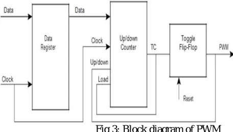
The implementation of simple PWM using ALTERA FPGAs is described here. The basic principle in PWM is the usage of register to store the value and it loads the Up/Down Counter whenever the counter reaches its terminal count. To generate the pulse width modulation the terminal counter is used.
Fig 3: Block diagram of PWM
A. Functional description
A data register is used to store the value for the counter, this value determines the pulse width. The Up/Down Counter is loaded with a new value from the data register when the counter reaches its terminal count; a Toggle Flip-flop generates the PWM output in figure 3.When the data value is first loaded, the counter begins to count down from the data value to 0. During this phase of operation the terminal count and PWM signals are Low. When the counter transitions through 0, the terminal count is generated and it triggers the Toggle Flip-flop to drive the PWM signal High. The data value is re-loaded and counting proceeds up to the maximum value. Again a terminal count will be generated when the counter reaches its maximum value, driving the PWM signal to toggle from High to Low. The data value is re-loaded and the cycle repeats. The direction of the counter is controlled by the PWM signal: the counter is set to count down when the PWM is Low, and count up when the PWM is High. The terminal count controls the data value that loads to the counter from the data register. Data is loaded when the terminal count is High.
The duty cycle of the PWM signal is controlled by the data value loaded to the up/down counter. The duty cycle of the PWM output can be varied by specifying various data values, the higher the data value, higher the duty cycle (see Table 1).
Data Value Duty Cycle (%)
11100110 90
11000000 75
10000000 50
01000000 25
[image:4.612.178.406.229.359.2]00011001 10
Technology (IJRASET)
©IJRASET: All Rights are Reserved
[image:5.612.185.416.72.160.2]37
Fig 4: Sample PWM output waveform Duty Cycle is calculated by taking the ratio of Mark Period and Frame Period:
Duty Cycle = Mark Period/Frame Period
= Data Value/2n.
Mark Period = Data Value x Tclock.
Frame Period = Tclock x 2n
where “n” is the binary counter width.
V. ANALOG TO DIGITAL
A. Converter
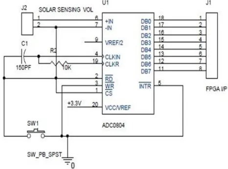
The ADC circuit which converts the input analog value into its equivalent digital value. The analog input from the solar panel is given to the ADC circuit to convert into digital value which is then given to the FPGA block. The pin configuration of ADC is shown in figure 5.
Fig 5: ADC0804 pin configuration
Analog to digital conversion calculation:
Vanalog= 4.2v
Vref+= 5v
Vref-= 0v
[image:5.612.158.391.398.570.2]Technology (IJRASET)
©IJRASET: All Rights are Reserved
38
((Vanalog/((vref+)-(vref-))*2^a/dresolution -1) = Digital value
=((4.2/(5-0.0))*(2^8-1))
=0.84*255
=214
=110101102
VI. HARDWARE MODULE
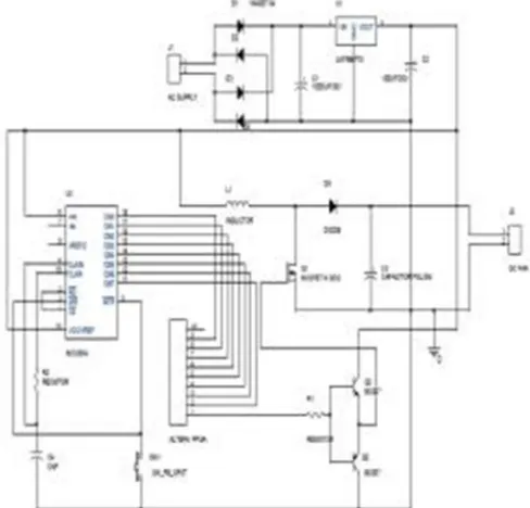
[image:6.612.176.393.225.389.2]The design of FPGA control unit for solar unit includes the voltage divider block, a DC-DC converter block, an ADC interface and an FPGA unit.
Fig 6: FPGA control unit
The analog value from the solar panel is given as an input to the DC-DC converter circuit and then to voltage divider circuit. The voltage divider circuit which divides the voltage level and then sends it to the ADC circuit, here the analog voltage is converted into digital. According to the input value from the solar panel and the ADC value the PWM pulse is generated from the FPGA board. The output of the PWM pulse is given to the DC-DC converter where the signal is boosted accordingly to high or low. Once the battery is fully charged the voltage divider circuit at the output side will stop the flow and then the ADC circuit which gives the value to the FPGA board thus to stop the generation of PWM pulses.
[image:6.612.188.432.475.709.2]Technology (IJRASET)
©IJRASET: All Rights are Reserved
39
VII. RESULTS AND DISCUSSIONS
The design of FPGA control unit for solar application is simulated using QUATRUS simulator and is implemented in ALTERA CYCLONE board.
The simulation is done for various PWM pulses with different duty cycle. The frame period for the PWM pulse can be calculated as follows:
Frame period=2 n * T clock
The input frequency available is 50Hz, so the frame period will be 0.02. The Tclock can be calculated as
T clock = 0.02/256 =78.125µSec.
Hence the frequency to generate the PWM pulse will be
F = 1/T clock
=(1/78.128) MHz F = 12.8 KHz.
By calculating the input frequency for the PWM the count value can be calculated as:
Count = input frequency / required frequency
= 50Hz / 12.8KHz Count = 3906.25
With this Count value the PWM counter up counts /down counts the value and boosts the voltage and maintains constant voltage to the battery.
The simulation results are shown below:
Technology (IJRASET)
©IJRASET: All Rights are Reserved
40
This simulation result is for final integration with reset value low.
VIII. HARDWARE IMPLEMENTATION
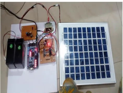
Finally this design has been implemented in ALTERA CYCLONE board, which requires 50Hz frequency for its startup. The board has 144 pins and a 50MHz crystal oscillator. The device series used to implement this design is EC1C37144C8N. The board is powered by 5V DC supply or a USB cable.
[image:8.612.203.439.159.337.2]The hardware is interconnected with an ADC circuit, MPPT circuit and a power circuit figure 8.
Fig 8: hardware implementation of FPGA unit
IX. CONCLISION
The design of FPGA control unit for solar application includes an ADC, MPPT circuit. The system consisting of the dc/dc converter performing the MPPT function has been presented in this paper.
The PWM generating signal for 12.8 KHz frequency from MPPT is applied to boost DC converter. The output voltage of DC-DC booster converter is stored in battery for further real time application usages. The results shown in this paper demonstrate that the technique allows estimating accurately the power response settling time by accounting the converter dynamic response, and the uncertainties affecting any real system.
REFERENCES
[1] J.L. Sawin (2011). Renewables 2011 Global StatusReport.[online].Available:http://www.ren21.net /REN21Activities/publications/GlobalstatusReport/G SR2011/tabid/56142/Default.aspx.
[2] N. Femia, G. Petrone, G. Spagnuolo, and M.Vitelli,“Power Electronics and Control Techniques for Maximum Energy Harvesting in Photovoltaic Systems”. CRC Press, 2013.
[3] Mattia Ricco, Patrizio Manganiello, Eric Monmasson,“FPGA-Based Implementation of Dual Kalman Filter for PV MPPT Applications,” IEEE transactions on industrial informatics, DOI 10.1109/TII.2015.2462313,2015.
[4] Fan Zhang, Kary Thanapalan, Andrew Procter, Stephen Carr, and Jon Maddy,“Adaptive Hybrid Maximum Power Point Tracking Method for a Photovoltaic System,” IEEE transactions on energy conversion, VOL. 28, NO. 2, JUNE 2013.
[5] Lakhdar Belhadji, Seddik Bacha, Member, IEEE, Iulian Munteanu, Member, IEEE, Axel Rumeau, and Daniel Roye,“Adaptive MPPT Applied to Variable-Speed Microhydropower Plant,” IEEE transactions on energy conversion, VOL. 28, NO. 1, MARCH 2013.
[6] Mr. S. K. Patil , Mr.D.K.Mahadik,“Design of maximum power point tracking (MPPT) based pv charger,” IOSR Journal of Electronicsl and Communication Engineering (IOSR-JECE) ISSN: 2278-2834-, ISBN: 2278-8735, PP: 27-33.
[7] Ahmed K. Abdelsalam,, Ahmed M. Massoud, Shehab Ahmed, and Prasad N. Enjeti, “High-Performance Adaptive Perturb and Observe MPPT Technique for Photovoltaic-Based Microgrids,” IEEE transactions on power electronics, VOL. 26, NO. 4, APRIL 2011.
[8] N. Femia, G. Petrone, G. Spagnuolo, and M. Vitelli, “Power Electronics and Control Techniques for Maximum Energy Harvesting in Photovoltaic Systems,”. Boca Raton, FL, USA: CRC Press, 2013.
[9] F. Zhang, K. Thanapalan, A. Procter, S. Carr, and J. Maddy, “Adaptive hybrid maximum power point tracking method for a photovoltaic system,” IEEE Trans. Energy Convers., vol. 28, no. 2, pp. 353–360, Jun. 2013.
[10] L. Belhadji, S. Bacha, I. Munteanu, A. Rumeau, and D. Roye, “Adaptive MPPT applied to variable-speed microhydropower plant,” IEEE Trans. Energy Convers., vol. 28, no. 1, pp. 34–43, Mar. 2013.
[11] F.-L. Luo and H. Ye, “Small signal analysis of energy factor and mathematical modeling for power dc–dc converters,” IEEE Trans. Power Electron., vol. 22, no. 1, pp. 69–79, Jan. 2007.
Technology (IJRASET)
©IJRASET: All Rights are Reserved
41
[13] Santos, J.L.; Antunes, F.; Chehab, A.; Cruz, C. (2006). “A maximum power point tracker forcPV systems using a high performance boost converter, Solar Energy,” Vol. 80, Issue 7, July 2006, pp. 772– 778, ISSN: 0038-092X.
[14] Yuanye Xia, Khaled H. Ahmed, and Barry W. Williams, “Wind Turbine Power Coefficient Analysis of a New Maximum Power Point Tracking Technique,”IEEE transactions on industrial electronics, VOL. 60, NO. 3, MARCH 2013.