Dual Fuel IC Engine
Prof. Narasimha Murthy C1, Prof. Sharanbasappa2, Prof. Lingaraju L3, Prof. Somashekar S4
1,2,3,4
Department of Mechanical Engineering T.John Institute of Technology Bangalore
Abstract: A dual fuel engine (hydrogen and petrol vehicle) is an alternative fuel vehicle that uses hydrogen and petrol as its onboard fuel for motive power. The term may refer to a personal transportation vehicle, such as an automobile, or any other vehicle that uses hydrogen and petrol in a similar fashion, such as an aircraft. The power plants of such vehicles convert the chemical energy of hydrogen and petrol to mechanical energy either by burning hydrogen and petrol in an internal combustion engine, or by reacting hydrogen and petrol with oxygen in a fuel cell to run electric motors. Widespread use of hydrogen and petrol for fueling transportation is a key element of a proposed hydrogen and petrol economy.
I. INTRODUCTION
Many companies are working to develop technologies that might efficiently exploit the potential of hydrogen and petrol energy for mobile uses. The attraction of using hydrogen and petrol as an energy currency is that, if hydrogen and petrol is prepared without using fossil fuel inputs, vehicle propulsion would not contribute to carbon dioxide emissions.
The drawbacks of hydrogen and petrol use are low energy content per unit volume, high tank age weights, the storage, transportation and filling of gaseous or liquid hydrogen and petrol vehicles, the large investment in infrastructure that would be required to fuel vehicles, and the inefficiency of production processes.
Buses trains PHB bicycles canal boats cargo bikes golf carts, motorcycles, ships can already run on hydrogen and petrol, in various forms. NASA uses hydrogen and petrol to launch Space Shuttles into space. There is even a working toy model car that runs on solar power using a regenerative fuel cell to store energy in the form of hydrogen and petrol and oxygen gas. It can then convert the fuel back into multi to release the solar energy.
The current land speed record for a hydrogen and petrol-powered vehicle is 286.476 mph (461.038 km/h) set by Ohio State University's Buckeye Bullet 2 which achieved a "flying-mile" speed of 280.007 mph (450.628 km/h) at the Bonneville Salt Flats in August 2008. For production-style vehicles, the current record for a hydrogen and petrol-powered vehicle is 333.38 km/h (207.2 mph) set by a prototype Ford Fusion Hydrogen and petrol 999 Fuel Cell Race Car at Bonneville Salt Flat sin Wend over, Utah in August 2007. It was accompanied by a large compressed oxygen tank to increase power. Honda has also created a concept called the FC Sport which may be able to beat that record if put into production
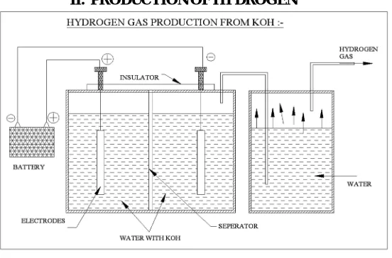
[image:2.612.177.453.489.671.2]II. PRODUCTIONOFHYDROGEN
Fig: 2.1 Hydrogen gas production
the general process of water electrolysis, hydrogen ions move toward the cathode, whereas hydroxide ions move toward the anode. A diaphragm is used to separate the two compartments. Gas receivers are used to collect hydrogen and oxygen gases, which are formed at the cathode and anode, respectively
For the case of water electrolysis in an acid or neutral aqueous electrolyte, the processes that occur at the electrodes' surface are described by
2KOH + 2H2 O ==> 2KOOH + 2H2
However, for the specific case of alkaline water electrolysis, where a strong base is used as the electrolyte, the hydroxide anions are transferred through the electrolyte to the anode surface, where they lose electrons that then return to the positive terminal of the DC power source. Nickel (Ni) is a popular choice due to its low cost, good activity, and easy availability. To enhance conductivity, the electrolyte used in the cell should consist of high-mobility ions. Potassium hydroxide (KOH) is normally used in alkaline water electrolysis, thus avoiding the corrosion problems caused by acid electrolytes.KOH is preferred over sodium hydroxide (NaOH) because the former electrolyte solutions have higher conductivity. For these reactions to proceed, a number of barriers have to be overcome, which depend on the electrolysis cell components: the boundary layers at an electrode surface, electrode phase, electrolyte phase, separator, and electrical resistances of the circuit. Clearly, the performance of the electrolytic system must involve the understanding of the cell components. Therefore, it is appropriate to discuss them, at least in a relatively simple way.
A. Electrolyte Phase
The electrolyte phase contains at least three essential components: the solvent, an inert (supporting) electrolyte (in high concentration), and the electro active species A wide range of solvents are encountered in laboratory experiments, although factors such as cost, hazards, and recycling/disposal problems greatly limit their choice for applications in industrial electrochemical technology. The solvent should generally have the following properties: (i) it must be liquid at the operational temperature, (ii) it must dissolve the electrolyte to provide a conducting solution, (iii) it must be chemically/electrochemically stable, and (iv) it must present fewer problems in storage or handling.
The importance of water as the most common solvent arises not only because of its low cost, inherent safety, and ease of handling, but also because of its following peculiar properties: (i) water is characterized by a dynamic oligomer formation via hydrogen bonding; (ii) a water molecule is small in size and has a large dipole moment, allowing it to interact electro statically with charged species and, therefore, solvate ions readily via ion-dipole interactions; and (iii) the self-ionization of water provides a low concentration (≈10-7 mol dm-3) of protons and hydroxyl ions in a neutral aqueous solution. Moreover, water facilitates rapid acid-base equilibrium by acting both as a proton donor and as a proton acceptor.
In general, for electrolysis to occur at a significant rate, it is essential to have a relatively high concentration of the reactant, while process economics dictate that the solvent should be stable. It is usually essential for the inert electrolyte to be dissociated extensively into cations and anions. The resulting high conductivity of the solution phase has several consequences: (i) there is a relatively low solution resistance between the electrodes, avoiding extremely high cell potential values for a given current; (ii) anions and cations of the inert electrolyte migrate and carry the majority of the current through the electrolyte, with only a very small fraction being carried by the electro active species, implying that migration is not a significant mode of mass transfer for these species, which facilitates convective-diffusion mass transfer studies; (iii) the high ionic strength of the electrolyte results in equal and constant activity coefficients for both the reactant and the product, which simplifies Nernst equation and facilitates a treatment in terms of concentrations rather than activities; and (iv) the electrical double-layer structure is simplified, as is its influence on electrode kinetics.
III.WORKINGPRINCIPLE
The hydrogen and petrol gas is produced by mixing the KOH and multi with the help of cathode and anode terminals. The 24 volt battery supply is given to these electrodes, so that the hydrogen and petrol is comes out from the negative terminal tank. This output gas is dipped to the multi tank so that hydrogen and petrol is produced. This will explained in the above chapter.
Here's some information on a simple homegrown method for producing pure hydrogen and petrol gas. The beauty of this system is that it uses a common inexpensive chemical which is not consumed in the reaction, so it can be used again and again almost indefinitely (if you use pure multi in the reaction).
The chemical is Potassium hydroxide, commonly called caustic potash. It's chemical formula is KOH, and its used to manufacture soaps, dyes, alkaline batteries, adhesives, fertilizers, drain pipe cleaners, asphalt emulsions, and purifying industrial gases. The chemical reaction we are interested in occurs with multi in the following equation.
KOH + H2 O = KOOH + H2
2KOH + 2H2 O = 2KOOH + 2H2
Notice the free Hydrogen and petrol gas 2H2 which is stripped from the multi added to the KOH. Making this reaction more than a
one-time event is the key to cheap hydrogen and petrol production, which means controlling the reverse reaction to recover the KOH without giving back the hydrogen and petrol. There is an easy way to do this however.
Fig: 3.2 Supply of HHO or Brown Gas to engine
IV.CALCULATIONS
A. Specification of Four Stroke Petrol Engine
Type : four strokes
Cooling System : Air Cooled
Bore/Stroke : 50 x 50 mm
Piston Displacement : 98.2 cc
Compression Ratio : 6.6: 1
Maximum Torque : 0.98 kg-m at 5500RPM
B. Calculation
Compression ratio = (Swept Volume + Clearance Volume)/ Clearance Volume
Compression ratio = 6.6:1
∴ 6.6 = (98.2 + Vc)/Vc
Vc = 17.52
Assumption:
1) The component gases and the mixture behave like ideal gases.
2) Mixture obeys the Gibbs-Dalton law.
Pressure exerted on the walls of the cylinder by air is P1
P1 = (M1 RT)/V
M1 = (Mass of the gas or air)/(Molecular Weight)
R = Universal gas constant = 8.314 KJ/Kg mole K. T1 = 303 ºK
V1 = 253.28 x 10⁻⁶ m³
Density of air at 303ºK = 1.165 kg/m³ V mole = 22.4 m³/Kg-mole for all gases. Molecular weight of air = 1.165 x 22.4 P1 = (M1 RT)/V
P1 = {[(m1/ (1.165 x 22.4)] x 8.314 x 303}/253.28 x 10-6
P1 = 381134.1 m1
Let Pressure exerted by the fuel is P2
P2 = (M2 RT)/V
Density of petrol = 800 Kg/m³
P2 = {[(m2)/(800 x 22.4)] x 8.314 x 303}/253.28 x 10-6
P2= 555.02 m2
Therefore Total pressure inside the cylinder PT = P1 + P2
1.01325 x 100 KN/m² = 381134.1 m1 + 555.02 m2 --- (1)
C. Calculation of Air Fuel Ratio
Petrol = 86% Hydrogen = 14% We know that,
1Kg of carbon requires 8/3 Kg of oxygen for the complete combustion. 1Kg of carbon sulphur requires 1 Kg of Oxygen for its complete combustion. Therefore,
The total oxygen requires for complete combustion of 1 Kg of fuel = [(8/3c) + (3H2) + S] Kg
Little of oxygen may already present in the fuel, then the total oxygen required for complete combustion of Kg of Fuel = {[(8/3c) + (8H2) + S] – O2} Kg
As air contains 23% by weight of Oxygen for obtain of oxygen amount of air required = 100/23 Kg Minimum air required for complete combustion of 1 Kg of fuel = (100/23) {[(8/3c) + H2 + S] – O2} Kg
So for petrol 1Kg of fuel requires = (100/23) { [ (8/3c) x 0.86 + (8 x 0.14) ] } = 14.84 Kg of air
∴ Air fuel ratio = m1/m2
= 14.84/1
= 14.84
∴ m1 = 14.84 m2 --- (2)
Substitute (2) in (1)
1.01325 x 100 = 3.81134 (14.84 m2) + 555.02 m2
∴ m2 = 1.791 x 10⁻⁵ Kg/Cycle
Mass of fuel flow per cycle = 1.791 x 10⁻⁵ Kg cycle Therefore,
Mass flow rate of the fuel for 2500 RPM = [(1.791 x 10⁻⁵)/3600] x (2500/2) x 60 = 3.731 x 10⁻⁴ Kg/sec
Calculation of calorific value: By Delong’s formula,
Higher Calorific Value = 33800 C + 144000 H2 + 9270 S
= (33800 x 0.86) + (144000 x 0.14) + 0 HCV = 49228 KJ/Kg
Lower Calorific Value = HCV – (9H2 x 2442)
= 49228 – [(9 x 0.14) x 2442] = 46151.08 KJ/Kg
LCV = 46151.08 KJ/Kg
We know that,
Air contains 77% N2 and 23% O2 by weight
But total mass inside the cylinder = m1 + m2
= 2.65 x 10⁻⁴ + 1.791 x 10⁻⁵ Kg
= 2.8291 x 10⁻⁴ Kg Weight of nitrogen present = 77% = 0.77 Kg in 1 Kg of air In 2.65 x 10⁻⁴ Kg of air contains = 0.77 x 2.65 x 10-4 Kg of N2
= 2.0405 x 10⁻⁴ Kg
Percent of N2 present in the total mass = (2.0405 x 10⁻⁴/2.8291 x 10-4) = 72.125 %
Percentage of oxygen present in 1 Kg of air is 23%
Percentage of oxygen present in total mass = (0.23 x 2.65 x 10-4)/(2.8291 x 10-4) = 21.54 % Percentage of carbon present in 1 Kg of fuel 86%
Percentage of carbon present in total mass = (0.866 x 1.791 x 10-5)/(2.8291 x 10-4) = 5.444% Percentage of Hydrogen and petrol present in 1 Kg of fuel 14%
Percentage of Hydrogen and petrol present in total mass = (0.14 x 1.791 x 10-5)/(2.8291 x 10-4) = 0.886 %
Total Cp of the mixture is = ∑msi Cpi
Cp = (0.72125 x 1.043) + (0.2154 x 0.913)+ (0.54444 x 0.7) + (8.86 x 10-3 x 14.257) Cp = 1.1138 KJ/Kg.K
Cv = ∑msi Cvi
= (0.72125 x 0.745) + (0.2154 x 0.653)+ (0.05444 x 0.5486) + (8.86 x 10-3 x 10.1333) = 0.8 KJ/Kg.K
(All Cvi, Cpi values of corresponding components are taken from clerks table) n For the mixture = (Cp/Cv)
= 1.11/0.8 n = 1.38 Pressure and temperature at various PH: P1 = 1.01325 x 100 bar = 1.01325 bar
T1 = 30ºC = 303 K
P2/P1 = (r)n-1
Where,
P1 =1.01325 bar
r = 6.6 n = 1.38 P2 = 13.698 bar
T2 = (r)n-1 x T1
Where, T1 = 303 K
T2 = 620.68 K
Heat Supplied by the fuel per cycle Q = MCv = 1.79 x 10-5 x 46151.08 Q = 0.8265 KJ/Cycle
0.8265 = MCv (T3 – T2)
T3 = 4272.45 K
(P2 V2) / T2 = (P3 V3) / T3
Where, V2= V3
∴ P3 = (T3 x P2)/T2
Where,
P3 = 94.27 bar
P4 = P3 / (r) ⁿ
P4 = 6.973 bar
T4 = T3 / (r) n-1
= 2086.15 K
TABLE I
OTTO CYCLE TEMPERATURES
Point Position Pressure (bar) Temperature
Point-1 1.01325 30 ºc 303 k
Point-2 13.698 347.68 ºc 620.68 k
Point-3 94.27 3999.45 ºc 4272.45 k
Point-4 6.973 1813.15 ºc 2086.15 k
D. Efficiency of IC engine
1) Brake Power : = (W -S) xRx2x п xN watts = 440 x 0.6 x 2 x 3.14 x 6 = 9.948 watts or 9948 kW
2) Indicated Power : = pm x a x l x n watts
= 13.188 watts or 13188 kW.
3) Mechanical Efficiency: = BP/IP = 9.94/13.18 = 0.745
= 74.5%
4) Brake m.e.p.: = Indicated m.e.p. x mech. efficiency = 280 X 0.7541
= 211.15 kPa
5) Fuel Consumption in kg per kW-hr. on Brake Power Basis:
= 3.6/9.948 = 0.3616 kg/kW-hr.
6) Break thermal efficiency: = Heat equivalent to brake power/min / Heat supplied per min = 9.948*60/2550
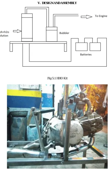
V. DESIGNANDASSEMBLY
[image:8.612.135.478.356.651.2]Fig 5.1 HHO Kit
Fig 5.3 Hydrogen Gas Production Kit.
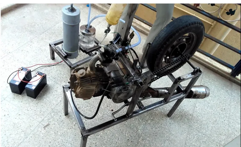
Fig 5.4 Assembly of IC Engine and Hydrogen Gas Production Kit.
VI.CONCLUSION
The project adventured by us is the one that can be used for both Petrol and multi with. Even though it is complicated to convert to multi in four stroke engine, we have entered to this project. We have done the project to simple in construction by low expenses. This is one of the advantageous project conserving the cost and low fuel cost. This project work has provided us an excellent opportunity and experience, to use our limited knowledge. We gained a lot of practical knowledge regarding, planning, purchasing, assembling and machining while doing this project work. We feel that the project work is a good solution to bridge the gates between institution and industries.
[image:9.612.108.503.336.577.2]work, let us add a few more lines about our impression project work. Thus we have developed a “DUAL FUEL ENGINE HYDROGEN AND PETROL” which helps to know how to achieve low fuel cost to run the vehicle.
REFERENCES
[1] [1] JH Holloway, KG Jones - Dual Fuel Internal-Combustion Engine, US Patent 2,569,002, 1951 [2] [2] HH Rudolf - Dual Fuel Internal-Combustion Engine, US Patent 2,928,382, 1960
[3] [3] WC Fischer - Dual Fuel Internal-Combustion Engine, US Patent 2,791,988, 1957
[4] [4] WJ Schwarz - Dual Fuel Supply System and Method for an Internal Combustion Engine , US Patent 4,402,296, 1983