©IJRASET: All Rights are Reserved
318
Modelling & Analysis of Shunt Active Power Filter
for Thd Reduction of Input Source Current in
12-Pulse Rectifier Circuit Load
KM Jyoti1, Dr. A.K. Bhardwaj2
1Pg Scholar, 2Professor, Department of Electrical Engineering, Shuats, Allahabad
Abstract: In this paper we have presented a MATLAB-SIMULINK model of Shunt Active Power Filter, and 12-pulse rectifier
circuit. We have discussed the design of the 12-pulse rectifier for input harmonics reduction with negligible change in source voltage. Due to the non-linear nature of the rectifier circuits, the harmonics generated can be harmful for the load and its causes heating effect. Due to this phenomenon power loss occur. We need to reduce it with some effective controller that can deal with non-linearity effectively. Thus, we have designed a fuzzy based Shunt Active Power Filter. Our simulation results analyzed the THD% using FFT analysis of the input current. Hence, the harmonics of the system has been reduced proving its usability. Keywords— Harmonics, 12-pulse converter, fuzzy controller, THD Analysis, Shunt Active Power filter
I. INTRODUCTION
With the increase in development of the Power distribution systems and power equipments, the need to maintain the power quality has been a challenge. We are well aware that with the increase of the complexity of load and power distribution, the load nature can’t be precisely assumed. But our aim is to maintain the Quality of Services (QoS) to ensure right power quality distribution. As we know, due to nature of the generation and then transmission equipments, the supply is AC in nature and supplied in sinusoidal form. The signals that are supplied are low pass in nature and thus are prone to the high frequency components. In such case, the problem of the high order harmonics arises and need to mitigate in order to ensure the good quality of power distribution. However, the main problem of the harmonics arises due to the non-linear nature of loads like diodes, non-linear electrical components. They tend to add higher order harmonics to degrade the quality of power.
Rectifiers are considered as basic element in power conversion to ensure appropriate supply of form of energy to the load. Various topologies of the multi-pulse rectifiers are found like 6-pulse, 12-pulse etc. Since, inputs harmonics are found to be more efficient since they have lesser input harmonics. In our work, we have considered that model of the 12-pulse rectifiers that act as non-linear load. These are commonly found in most of the charging circuits, preliminary supply circuits of various electrical and electronics equipment. Our aim is to reduce the input harmonics effectively for the 12-pulse diode based rectifier. We have presented a design based on the shunt Active power filter. We need to reduce the harmonics to minimize THD% to ensure quality of power. Controllers play an important role in functioning of the system. Conventional static controllers like PI, PID have several limitations for such non-linear rectifier systems. The PI controllers have several limitations since they are non-adaptive and non-robust for such high order non-linear loads. They require very precise design and pre-assumed non-linearity. However, for the dynamic scenario where the disturbance can’t be modeled with high precision, they seem to lose their efficiency. In this scenario, fuzzy controllers have advantages. They deal with non-linearity highly effectively. They can be effectively use at the place of for less precise models and unknown disturbances as well.
In our work, we are using the fuzzy logic controller for the design of the active power filter for the given system. This fuzzy logic controller is applied to reduce the input current harmonics for the 12-pulse rectifier circuitry. We have demonstrated that the input current harmonics have been reduced effectively.
II. SHUNTACTIVEPOWERFILTER
Huge amount of harmonics injects into the distribution system due to increasing usage of nonlinear loads like electric arc, welders, switching power supplies and speed drives. These harmonic current are the reason for voltage distortion, electronic equipment operation failure and high power losses etc.
With the help of filter circuit in non linear loads we remove harmonics from the source side.
©IJRASET: All Rights are Reserved
319
harmonic current equal in magnitude but opposite in phase and to those harmonic that are present in the grid. The Shunt Active Power filter with non linear load become a linear load.
In this circuit Shunt Active Power Filter(SAPF) acts as a current source. The principle of Shunt Active Power Filter is produce harmonic current equal in magnitude but opposite in phase and to those harmonic that are present in the grid. The Shunt Active Power filter with non linear load become a linear load.
A. Advantage
1) Guarantee compliance with IEEE519 1992 if sized it correctly. 2) Harmonic cancellation from the 2nd to 51st harmonic.
3) No series connection provide easy installation with no major system rework. 4) Provide VAR current improving system.
B. Disadvantage
1) Can be more expensive than other methods due to the high performance control and power section. 2) The filter input semiconductors are exposed to line transient.
III.FUZZYLOGICCONTROLLER
A Control System on mathematical system that analyzes analog input values values in terms of logical variable that take on continuous value between 0 and 1. In contrast to classical on digital logic, which operates on discrete values of either 1 or 0 ( true or false respectively
In any fuzzy logic controller operations are divided into three steps as A. Fuzzification
B. Fuzzy processing C. Defuzzification
©IJRASET: All Rights are Reserved
320
IV.SIMULINKMODEL
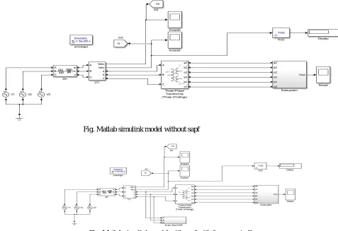
[image:4.612.67.544.119.446.2] [image:4.612.210.403.516.692.2]The Proposed matlab simulink model has been simulated using matlab simulation simscap power system tool box. Simulation model have three phase voltage are to be balanced. A load of this simulink model highly non linear characteristics
Fig. Matlab simulink model without sapf
Fig. Matlab simulink model with sapf with fuzzy controller
V. RESULTANDDISCUSSION
The following table presents the simulation parameters for our work. The system consists of AC sinusoidal supply of 230V (3-phase) with practical source impedance modeled. It consists of very highly non-linear load for simulation. Active Power filter has been designed for the same.
IGBT device have been used for DC link. And at last, fuzzy controller has been integrated in the filter. System Parameters Values
Supply Voltage 230V
Frequency 50 Hz
Source Impedence 0.05 Ohm, 0.05 H
Filter Inductance 0.2 Mh
Filter capacitor 2200 uF
DC Voltage 400V
Load
12- Pulse Rectifier
Load Impedance
©IJRASET: All Rights are Reserved
321
[image:5.612.189.435.90.233.2]VI.RESULTANDDISCUSSION
Fig.3 Input source current with non-linear load without fuzzy
Fig. 3 presents the simulation results obtained after simulation without any active power filter (shunt) in introduction
Fig4 Load current with non-linear load without fuzzy
[image:5.612.190.438.423.538.2]Fig. 4 presents the simulation results obtained after simulation without any active power filter (shunt) in introduction.
Fig.5Input source current with non-linear load with fuzzy
[image:5.612.189.433.569.711.2]Fig. 5 presents the simulation results obtained after simulation without any active power filter (shunt) in introduction.
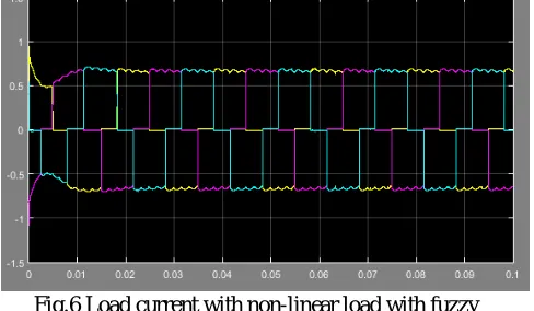
Fig.6 Load current with non-linear load with fuzzy
©IJRASET: All Rights are Reserved
322
Fig.7 Load current with non-linear load without SAPF
[image:6.612.182.432.76.272.2]Fig. 7 presents the simulation results obtained after simulation without any active power filter (shunt) in introduction.
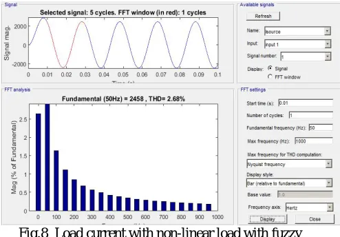
Fig.8 Load current with non-linear load with fuzzy
Fig. 8 presents the simulation results obtained after simulation without any active power filter (shunt) in introduction.
SIMULATION RESULTS
Before Compensation 4.32
After Compensation 2.68
VII. CONCLUSION
In this paper, we have presented MATLAB modeling for driving 12-pulse rectifier highly non-linear load by power source. Fuzzy controller has been used in designed for the shunt active power filter. We have demonstrated that the THD (%) can be reduced using the active power filter added shunt to the source.
[image:6.612.190.437.309.481.2]©IJRASET: All Rights are Reserved
323
REFERENCES
[1] HINK, KARL M.,“HARMONIC MITIGATION OF 12-PULSE DRIVES WITH UNBALANCED INPUT LINE VOLTAGES”, MTE CORPORATION.
[2] WILSON E.KAZIBWE AND MUCOKE H.SENDUALA :“ELECTRIC POWER QUALITYCONTROL TECHNIQUES”.NEW YORK: VAN NOSTRAND REINHOLD,1993. [3] N. MOHAN,“A NOVEL APPROACH TO MINIMIZE LINE- CURRENT HARMONICS IN INTERFACING POWER ELECTRONICS EQUIPMENT WITH PHASE UTILITY
SYSTEMS”,IEEE TRANS ON POWER DELIVERY, VOL.8, JULY.1993, PP 1395-1401.
[4] ELIAS M.STEIN, TIMONTHY S.MURPHY :“HARMONIC ANALYSIS: REAL-VARIABLE METHODS, ORTHOGONALITY AND OSCILLATORY INTEGRALS.”, PRINCETON,
N.J.:PRINCETON UNIVERSITY PRESS,1993.
[5] J.S.LAI AND T.S.KEY,“EFFECTIVENESS OF HARMONIC MITIGATION EQUIPMENT FORCOMMERCIAL OFFICE BUILDINGS,” IEEE TRANSACTIONS ON INDUSTRY APPLICATIONS,VOL.33, NO.4, SEP 1997, PP.1065-1110
[6] S.HANSEN, P.NIELSEN AND F.BLAABJERG,“HARMONIC CANCELLATION BY MIXING NONLINEAR SINGLE-PHASE AND THREE-PHASE LOADS,”IEE TRANSACTIONS ON INDUSTRY APPLICATIONS, VOL.36, NO.1,2000, PP.152-159.
[7] B.ACARKAN, S.ZORLU AND O.KILIS,“NONLINEAR RESISTANCE MODELING USINGMATLAB AND SIMULINK IN ESTIMATION OF CITY STREET LIGHTING HARMONIC ACTIVITY,”IEEE EUROCON ,THE INTERNATIONAL CONFERENCE ON COMPUTER AS A TOOL,VOL.2, NOV.2005, PP.1251-1254.
[8] A.DELL’AQUILA, G.DELVINO, M.LISERRE, P.ZANCHETTA,“A NEW FUZZY LOGICSTRATEGY FOR ACTIVE POWER FILTER,” IN: PROC.EIGHTH INT.CONF.ON POWERELECTRONICS AND VARIABLE SPEED DRIVES, SEPTEMBER 2000, PP.392–397(IEECONF.PUBL.NO.475).
[9] S. FAN, Y.WANG, “FUZZY MODEL PREDICTIVE CONTROL FOR ACTIVE POWER FILTER,”IN:PROC.IEEE INT. CONF. ON ELECTRIC UTILITY DEREGULATION,
RESTRUCTURING ANDPOWER TECHNOLOGIES (DRPT 2004), VOL.1, APRIL 2004, PP.295–300
[10] S.K.JAIN, P.AGRAWAL, H.O.GUPTA,“FUZZY LOGIC CONTROLLED SHUNT ACTIVE POWER FILTER FOR POWER QUALITY IMPROVEMENT,” IEE PROC.ELECTR. POWERAPPL.149(SEPTEMBER (5))(2002), PP317–328.