Comparative Analysis of Diagrid and Chevron
Braced Frame Structure under Dynamic Loading
Navneet Kumar1, M. C. Paliwal2 1
Student, 2Associate professor, Department of Civil and Environmental Engineering, National Institute of Technical Teachers' Training and Research, Bhopal India, M.P.
Abstract: The diagrid structures have proven to be highly adaptable in structuring a wide range of building types, spans and forms. In most of the applications, diagrid provides structural support to the buildings that are non rectilinear, adapting well to highly angular buildings and curved forms. The origin of the diagrid structural technology lies at the crossroads of engineering and architecture. The term “diagrid” have come from perimeter diagonals which have good structural efficiency and is gaining new interests in designing of tall structures because of its lattice like look. The term “diagrid” is a blending of the words “diagonal” and “grid” and refers to a structural system that gains its structural integrity through use of triangulation. In the diagrid structures, the vertical columns from the periphery are eliminated and this constructs the main difference between diagrids and chevron braced frame structures. Having triangulated configuration, the diagrids are able to carry the gravity and lateral loads. They also effectively reduce shear deformation as the diagonals carry the loads axially. The diagrid structural system is adopted these days for tall buildings because of its stiffness and flexibility in the architectural planning. This Dissertation paper represents the study of G+ 29 storeys in which “Diagrid structure is compared with chevron braced frame structure under dynamic loading.” Analysis results of both the models are presented in terms of Lateral displacement, top storey displacement, storey drift, material consumptions.
Keywords -Diagrid structures, Chevron braced frame structure, Dynamic analysis, STAAD pro, Storey displacement, Storey drift.
I. INTRODUCTION
supplementary method of support, the current (standard high-rise) diagrid system uses an exterior frame comprised exclusively of diagonal members as the primary means of support. If properly engineered, such systems can use less steel than conventionally framed tall buildings. Where early conventionally framed office towers did not necessarily strive for a column free interior, most diagrid towers work towards elimination of columns between the exterior structure and the core.A diagrid tower is models as a vertical cantilever. The size of the diagonal grid is analyzed by dividing the height of the tower into a series of modules. Numerous studies have been conduct towards the optimization of the module size as function of the building height and angles of the inclined members. Normally the height of the base module of the diamond grid will extend over several stories. In this way the beams that define the edge of the floors can frame into the diagonal members providing both connection to the core, support for the floor edge beams, and stiffness to the unsupported length of the diagonal member as a significant part of the cost simplifying the connection between the node and the diagonal to speed up erection. Usually shear wall core, braced frame and their combination with rakes are interior system, where lateral load is resist by centrally located elements. While framed tube, braced tube structural system resist lateral loads by elements provided on periphery of structure. It is very important that the selected structural system is such that the structural elements are utilized effectively, while satisfying design requirements. Recently diagrid structural system is adopted in tall buildings due to its structural efficiency and flexibility in architectural planning. Compared to closely space vertical columns in framed tube, diagrid structure consists of inclined columns on the exterior surface of building. Due to inclined columns lateral loads is resisted by axial action of the diagonal compared to bending of vertical columns in framed tube structure. Diagrid structures generally do not require core because lateral shear can be carried by the diagonals on the periphery of building [1].
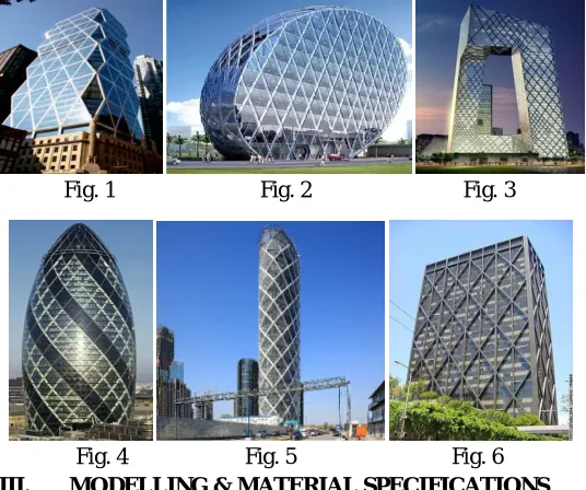
[image:3.612.174.442.355.579.2]Diagrid is a specific type of space truss; it is the texture of perimeter grid made up of a series of triangulated truss systems. The some examples of world-famous diagrid and braced frame structuresare shown in figure 1 to figure 5, i.e. fig. 1 Hearst Tower in New York. Fig. 2 Cybertecture Egg(under construction) in Mumbai, India, fig. 3 CCTV Beijing, China, fig. 4 Swiss re in London, fig. 5 Poly international plaza(under construction), Beijing, China, fig 6 Alcoa building, California USA.
Fig. 1 Fig. 2 Fig. 3
Fig. 4 Fig. 5 Fig. 6
III. MODELLING & MATERIAL SPECIFICATIONS
The modelling and analysis of a G+29 storey diagrid and chevron braced frame model is analysed by using STAAD.pro V8i software. The modelling data is listed below. The sizes of members are obtains from the analysis for both the model are given in the table-1
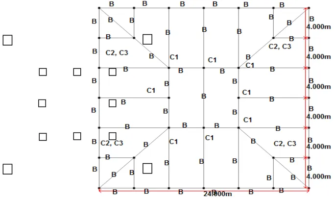
A. Both models with 24X24m plan dimension, and 3m height of each storey is taken.
B. The dead load is taken 4kN/m2 on floor level.wall load at floor level beams is 5KN/m and terrace level beams is 2KN/m. The live load is taken 2KN/m2 on terrace level and 4kN/m2 on floor level of both the models, as per IS 875-1987, part-I and part-II. C. The seismic effects on the buildings are taken as zone
factor 0.1, soil type II, Importance factor 1.5,Response Reduction 5 and Damping ratio 5% as per IS-1893-2002. For Bhopal location.
The Supports are taken fixed. Hinged condition is applied to diagrids only.
[image:4.612.164.449.143.401.2]The characteristics compressive strength of concrete is 40 N/mm2 for columns and 30 N/mm2 for slab. The yield strength of main reinforcement 415 N/mm2 in columns and slabs. The yield strength of steel is 250 N/mm2 and the ultimate tensile strength is 420 N/mm2.
Table-1 Structural members specifications and design data.
Members Membe rs no Diagrid Structure Chevron Braced frame Structure Propertie s
Beams B ISMB550 ISMB550 Steel
Interior columns
C1 1X1 M. 1X1 M.
Concrete C2 1.2X1.2 M. 1.2X1.2 M.
C3 1.4X1.4 M. 1.4X1.4 M.
Exterior
columns ISMB600 Steel
Slabs S1
0.12 M., thickness with 20mm cover 0.12 M., thickness with 20mm cover Concrete Bracing
s b1
ISA 200X200X25
ST
Steel
Diagrid
s D1
450mm pipe25mm
thick.,
=56018’
Steel
The interior column C3 is only in ground floor in both structures.
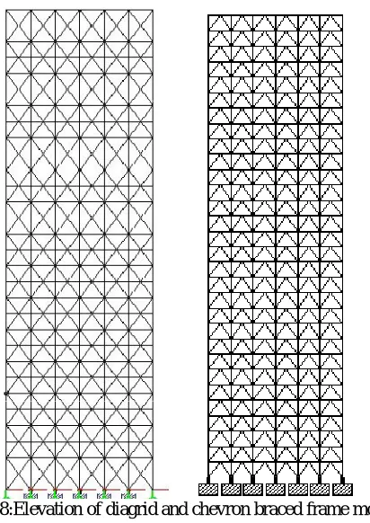
[image:4.612.89.430.487.691.2]The diagrid and chevron braced frame structure are analyzed here by STAAD.PRO. The final process of the structural analysis is the post processing of the diagrid and chevron braced frame structure for seismic and wind load analysis. As per the solution, we can check the comparative analysis results of both structures in different aspects of suitable design lateral load, wind load and earthquake load whichever will be greater than it is further analyzed for lateral displacement, top storey displacement, storey drift and material consumption.
Figure 8:Elevation of diagrid and chevron braced frame model.
IV. RESULTS & DISCUSSION
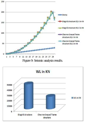
The obtained comparative analysis results of both structureshas been tabulated andplotted as followings, in all line diagrams below, the total lateral force due to earthquake and wind in x and z direction of both structures are plotted.
From the analysis, it is found that amount of wind load is Greater than earthquake load and hence, wind load dominates in the design of both the structural models.
Table 2 Total lateral forceson both structures after analysis.
Type of load Diagrid structure Chevron braced frame structure
Earthquake in
X-direction 2257.139KN 2201.630KN
Earthquake in
Z-direction 2257.139KN 2201.630KN
Wind in
X-direction 47029.88KN 23739.61KN
Wind in
Z-direction 47029.88KN 23739.61KN
[image:5.612.174.439.471.659.2]Figure 9: Seismic analysis results.
Figure 10: Wind load analysis result.
Figure 12: Comparative lateral displacement results.
Figure 13: Top storey displacement results of both models.
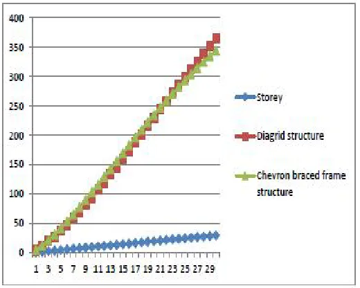
The storey drift shall not be exceed 0.004 times the storey height. So, maximum limit of storey drift is 12cm.
Figure 13: Storey drift of both structures. 330
335 340 345 350 355 360 365 370
Diagrid structure
[image:7.612.168.444.553.711.2]V. METERIAL CONSUMPTION
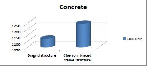
[image:8.612.150.464.123.264.2]The quantities of concrete and steel required have calculated in both the buildings. It has noted that the consumption of concrete and steel for chevron braced frame model is more than the diagrid model by 9.946% and 14.946% respectively.
Figure 14: Concrete consumption.
Figure 15: Steel consumption.
VI. CONCLUSIONS AND FUTURE SCOPE
The diagrid structure resists approximately the dual amount of lateral loads as compared to the chevron braced frame structure, despite all the vertical columns being eliminated in the periphery of the diagrid structure.
A. Diagrid structure provides more efficiency than chevron braced frame structure.
B. Also, same amount of lateral displacement seen in diagrid structure and thechevron braced frame structure.
C. The top storey drift of diagrid structure is more by 36.7% than in the chevron braced frame structure; and both structures has passed in storey drift acceptable limit.
D. The top storey displacement of diagrid structure is more by 5.50% than in the chevron braced frame structure. E. All these factors make the diagrid structure more resistant than the chevron braced Frame structure.
F. Diagrid structure gives more aesthetic look and gives more of interior space due to less columns and façade of the building can also be planned more efficiently.
G. The material consumption value is approx same for we use ISMB 600 as exterior column in chevron braced frame structure. If we used all exterior concrete column in chevron braced frame structure then material consumption varies more.
H. Diagrid structure system provides more economy in terms of consumption of steel and concrete as compared to chevron braced frame structure.
The diagrids is being used for tall and complex building construction. The unique characteristic ofdiagrid structure is to gives greater structural efficiency for tall buildings. Due to increase in population, the multi-storey building construction will continue on a larger scale. This work can be advanced and improved with consideration of following parameters:
K. A comparison on the basis of different size of diagrid module can also be done. L. Analysis can be performed for different seismic/ wind zones.
M. The design of diagrid node connections and its effect on overall economy of building can be studied.
N. Comparing the diagrid system with other lateral load resisting system such as differet-different bracing, shear wall etc. can also be studied.
O. A study considering the stiffness of floor system in the analysis can included in the design.
VII. REFERENCES
[1] Khushbu Jani and Paresh V. Patel, “Analysis and Design of Diagrid Structural System forcHigh Rise Steel Buildings”, Published by Elesevier Ltd,Procedia Engineering 51, pp 92 100,2013
[2] Kyoung S. Moon, Jerome J. Connor and John E. Fernandez, “Diagrid Structural Systems for Tall Building: Characteristics and Methodology for Preliminary Design” Willey Interscience Publication.
[3] Kyoung S. Moon, “Diagrid Structures for Complex-Shaped Tall Building”, Published by Elesevier Ltd, Procedia Engineering 14, pp 1343-1350,2011. [4] Mir M. Ali and Kyoung S. Moon, “Structural Developments in Tall Buildings: Current Trends and Future Prospects”, Architectural Science Review, vol. 50.3,
pp 205-223, 2007.
[5] Kim, Y.Jun and Y.-Ho Lee, “Seismic Performance Evaluation of Diagrid System Buildings”, 2nd Specially Conference on Disaster Mitigation, Manitoba, 2010.
[6] Moon, K.S. (2005), Dynamic Interrelationship between Technology and Architecture in Tall Buildings, Ph.D. dissertation, Department of Architecture, Massachusetts Instituteof Technology.
[7] Milana, G., Gkoumas, K. And Bontempi, F. (2014), Sustainability Concepts in the Design of High-Rise Buildings: The Case of Diagrid Systems, Third International workshop on Design in Civil and Environmental Engineering, Denmark, pp. 170-179.
[8] Charnish B. and McDonnell T. “The Bow: Unique Diagrid Structural System for a Sustainable Tall Building”, CTBUH 8th World Congress, Dubai. [9] Rupa Garai et al. (2015) “Three dimensional exterior bracing systems for tall buildings” CTBUH 2015 New York conference
[10] Gerasimidis and moon“diagrid structural system for high-rise buildings: applications of a simple stiffness-based optimized design” published by International journal of High-Rise Building, Vol. 05, No 4, 319-326, December 2016
[11] IS 456:2000 “plain and reinforced concrete- code for practice” (Fourth Revision), BIS New Delhi. [12] IS 800:2007 “general Construction in Steel – code of Practice” (Third Revision), BIS New Delhi.
[13] BS 8007:1987 British standard code of practice for design of concrete structure for retaining aqueous liquids.
[14] IS875 (part 1):1987, “Code of practice for design load (other than earthquake) for building and structures” BIS, New Delhi, 1987.IS 875(part 2) 1987 “Code of practice for design load (other than earthquake) for building and structures” BIS, New Delhi.