Technology (IJRASET)
Intelligent Train Engine and Running System
Sumit Dwivedi1, Shubhankar Tiwari2, Ravi Mohan Singh3, Swati Sharma4
Bachelor of Technology, Department of Electronics and Communication, SRM University NCR Campus, India.
Abstract – This paper is an attempt to improve the currently running railway system by automation of the rail engine and the unmanned railway crossing gates. This system is designed to automatically change speed in accordance to the signal light, replace manned crossing gates with automated gates and avoid collisions between trains on the same track. Since the operation is automatic, errors due to manual operations are prevented. This is achieved using AT89C51 Microprocessors and infrared sensors.ULN2000 relay driver IC is used to drive the relays and hence control the gates. Voltage regulators and 555 timers are suitably used.
Index terms- automation, AT89C51 microprocessor, ULN2000, relays, voltage regulator, 555 timer
I. INTRODUCTION
With the increasing demand for railway services, more strict safety requirements for railway control and infrastructure are needed. Accompanying that trend, in recent years, automated system has advanced rapidly. With the advancement in the microprocessor technology, it is possible to develop an effective fully automated system for railway infrastructure. This report is an attempt to optimize the railway operation by automation of engine and advanced hazard and accidental control in a cost effective manner. This system comprises a digital control circuit and a driving circuit. This system is designed using the AT89C51microproccessor on a printed circuit board. The system includes infrared and magnetic sensors, 555 timer, and crystal oscillator etc. to achieve the required.
A. Circuit Component Analysis
This circuit basically consists of the following major components.
1) AT89C51 Microprocessor – It is a low-power, high-performance CMOS 8-bit microcomputer with 4KB Flash programmable and erasable read only memory. The Flash memory allows the program memory to be reprogrammed. The Idle Mode stops the CPU while allowing the RAM, timer/counters, serial port and interrupt system to continue functioning. The Power-down Mode saves the RAM contents but freezes the oscillator disabling all other chip functions until the next hardware reset.
2) 555 Integrated Circuit-This IC is a highly stable monolithic timing controller that is generally used for producing accurate time delays. The free running control frequency and the duty cycle are accurately controlled by one capacitor and two external resistors for a stable operation. This integrated circuit contains nearly 25 transistor 10-12 resistors and a few diodes. In this circuit the duty cycle is adjustable, and the output operates in the normally on and normally off modes that can be used in driving Transistor-transistor logic devices. The 555chip is also used for pulse generation, sequential timing, precision timing, pulse width modulation, pulse position modulation and missing pulse detection.
3) Crystal Oscillator- Crystal oscillators are frequency producing devices where the primary frequency determining element is a quartz crystal. Because of the inherent and native characteristics of the quartz crystal, the crystal oscillator can be held to frequency stability with extreme accuracy. Temperature compensation may be applied to improve upon the thermal stability of the crystal oscillator. Crystal oscillators in general are fixed frequency oscillators where stability and accuracy are the primary concern. For example it is almost impossible to design a stable and accurate LC oscillator for the upper HF and higher frequencies without resorting to some sort of crystal control. Hence crystal oscillators are needed.
Technology (IJRASET)
Fig 1. Infrared Sensor
5) DC Motor – It is a device that produces rotatory motion when a current is passed through it. It works on the faradays principle of electromagnetic. In this circuit, the dc motor is used to drive the automated gates.
6) Magnetic Sensor- the magnetic sensor is based upon the Hall Effect. This circuit basically detects any change in magnetic field property such as flux, direction and strength. As soon as a magnetic field is bent upon a current carrying conductor, there is a change in the flux linked to the circuit and hence the sensing is achieved. This can be used to drive a mechanism for actuation which in turn can lead to a machine response.
7) Relays- relays are nothing but electrically operated switches that are generally used to actuate other mechanical components. It consists of a wire coiled around an iron core, an armature and spring system. As soon as the electric field is passed to the relay, magnetic field is generated which either makes or breaks connection with contact to the external driven component mdepending upon the previous state of the contact.
8) Other Components Used- Apart from the aforementioned components, the circuit also uses a 3-terminal voltage regulator, relays, electrolytic Other Components Used- capacitors, LED’s, NPN Transistors, a power supply and PVC wires for connections. All the components are attached to printed circuit board.
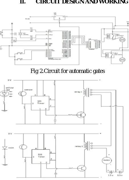
[image:3.612.189.416.353.670.2]II. CIRCUIT DESIGN AND WORKING
Fig 2.Circuit for automatic gates
Fig 3.Circuit for speed control and emergency brakes
Technology (IJRASET)
A. Automatic gate control
B. Speed control and anti-collision circuit The latter circuit is installed in the train engine.
The magnetic sensors are used for the opening and closing of the gates. A 9 V power supply is used to run the microcontroller via a three terminal voltage regulator. Crystal oscillator is used between pins XTAL1 and XTAL2 which act as input and output of an inverting amplifier to produce stable oscillations. The ULN2000 relay driver IC interfaces the two clockwise anticlockwise dc motor relays with the output port 2 of the microcontroller AT89C51.
As soon as the train is sensed on the track, the circuit gets actuated and the relay 1 runs the first motor which is connected in opposite polarity to the other motor. Hence the gate closes and previous gate opens up. Similarly when the next sensor is actuated, the relay 2 drives the 2nd motor in opposite direction to open it up and closes on crossing the next sensor.
In this manner the railway gates are automated.
The second circuit controls the speed of train as well as the emergency brakes against an object on track or caught between gates. Infrared sensor is installed on engine front. As soon as an object is detected in range of the sensor the relay actuates and breaks the power circuit to apply brakes.
Apart from that another light sensor drives a 555 timer circuit to a relay that is connected to the motor driving the train. When that light is sensed (in this case yellow) the motor is connected to half the power and hence slowing the train down.
III. RESULT AND CONCLUSION
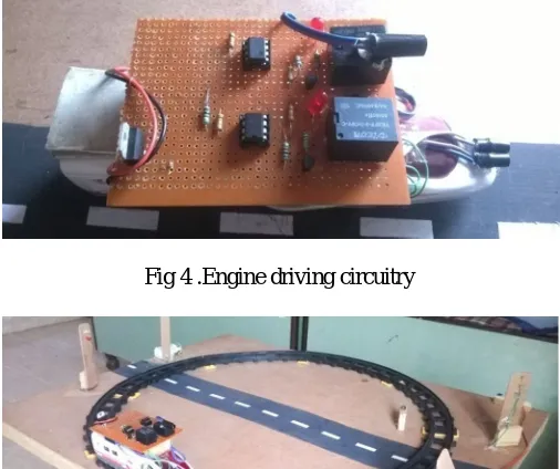
[image:4.612.181.436.376.489.2]The circuit for our project was designed and set up in a Printed circuit board. It is found to be very reliable and stable. This setup is built to reduce the human labor needed to run the facility as well as improves the safety of humans and life. All the setup was safely installed with total precaution without causing any unexpected losses.
Fig 4 .Engine driving circuitry
[image:4.612.180.433.382.594.2]Technology (IJRASET)
IV. FUTURE SCOPE
This project has a big scope of improvement with technology in future. The speed control mechanism could be improved by improving the light sensors and installing program based mechanism to control the speed. The safety at railway gates could be improved by installing load sensor to more precisely control the emergency brakes. Hence with better technology this model can be used for improving the current system that is being used to run the railway system.
V. ACKNOWEDGEMENT
We would like to sincerely thank Ms. Swati Sharma (project mentor) for her guidance without which this project could not be possible. We would also like to thank SRM University NCR campus for providing opportunity to build this project.
REFERENCES
[1] Kenneth J.Ayala,”8051 ,Microcontroller Architecture, Programming and Applications”,2nd Edition
[2] Muhammad Ali Mazidi and Janice Gillispie Mazidi, ”the 8051- Microcontroller and Embedded Systems”,7th edition, Pearson Education
[3] Subrata Biswas, ”Pressure Sensed Fast Response Anti Collision System for Automated Railway Gate Control”, American Journal of Engineering Research,Volume-2,Issue-11
[4] Roy Choudhary, Shail Jain, ”Linear Integrated circuits”, Wiley Eastern Limited
[5] Ramakant A. Gayakwad, ”Op-Amp and Linear Integrated Circuits”, 4th Edition, Pearson Education [6] Stanley G. Burns, Paul R. Bond, “Principles of Electronic Circuits, Galgotia Publishers
[7] Atul Kumar Dewangan, Meenu Gupta, ”Automation of Railway Gate Control Using Microcontroller”, International journal of Engineering Research and Technology,ISSN-2278-0181,Volume-1,issue-3,May 2012
[8] Krishna, Shashi Yadav, Nidhi, ”Automatic Railway Gate Control Using Microcontroller”,Oriental Journal Of Computer Science And Technology,Volume-6,No-4,December 2013