Technology (IJRASET)
Controlling and Protection of Three Phase
Induction Motor Using PLC
S.Sneha1, S.Radhika2
1
MTech Student Department of Electrical Engineering, GRIET, Hyderabad-500072
2
Asst Professor in the Department of Electrical Engineering, GRIET, Hyderabad-500072
Abstract— Automation is the process of handling various parameters of process like temperature, flow, etc. without presence of responsible person. In the development of automation controllers the trend has been to move towards soft controllers so as to provide better control, more flexibility and more reliability with intelligent diagnostics of machine faults. So industries have gradually moved from conventional relay logic control to PLC. Three phase TEFC 1induction motors are widely used motors in industry. The implementation of monitoring and control system for the induction motor based on programmable logic controller technology is described. Also the implementation of a hardware and software for speed control and protection with the result obtained from the test on induction motor performance is provided. Variable Frequency Drives (VFD) can also use to control the motor rotation direction and rotation speed of the three phase induction motor and protection of motor is done. All the required control and motor performance data will be taken to a personal computer via PLC for further analysis.
Keywords— Computer-controlled systems, Programmable Logic Control (P.L.C.), induction motors, Personal Computer (PC),
variable frequency drives, voltage control
I. INTRODUCTION
AC INDUCTION MOTORS (IMs) are used as actuators in many industrial processes. Although IMs are reliable, they are subjected to some undesirable stresses, causing faults resulting in failure. Monitoring of an IM is a fast emerging technology for the detection of initial faults. It avoids unexpected failure of an industrial process. Monitoring techniques can be classified as the conventional and the digital techniques.
Since technology for motion control of electric drives became available, the use of programmable logic controllers (PLCs) with power electronics in electric machines applications has been introduced in the manufacturing automation. AC induction motors (IMs) are used as actuators in many industrial processes. Although IMs are reliable, they are subjected to some undesirable stresses, causing faults resulting in failure. Monitoring of an IM is a fast emerging technology for the detection of initial faults. It avoids unexpected failure of an industrial process..Almost any production line, machine function or process can be automated using a PLC. The speed and accuracy of the operation can be greatly enhanced using this type of control system. But the biggest benefit in using a PLC is the ability to change and replicate the operation or process while collecting and communicating vital information. Since there were problems related to large electrical panels with a number of electrical components and extensive wiring, people felt the need for software logic controllers, so they gave birth to Programmable Logic Controller (P.L.C) wherein the control logic is developed in ladder diagram, a software logic control, with a number of inputs taken from the environment and generating the outputs, depending on the logic programmed, to the environment.
This helped to control any machine sequence with small electrical panels, less number of electrical components and less wiring with more flexibility to change machine sequence.
PLC provides higher accuracy as well as safe and visual environment compared with the classical, the computer, and the PIC-based protection system. Other performance parameters of three phase induction motors can also be monitored by the other control devices. Variable Frequency Drives (VFD) can also use to control the motor rotation direction and rotation speed of the three phase induction motor.
Technology (IJRASET)
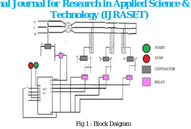
Fig 1 : Block Daigram
II. PROGRAMMABLE LOGIC CONTROLLER
A programmable logic controller is a specialized computer. Since it is a computer, it has all the basic component parts contained in any other computer, a central processing unit, memory, input interfacing, and output interfacing. PLC is a microprocessor-based control system, designed for automation processes in industrial environments. It uses a programmable memory for the internal storage of user-orientated instructions for implementing specific functions such as arithmetic, counting, logic, sequencing, and timing. A PLC can be programmed to sense, activate, and control industrial equipment and, therefore, incorporates a number of I/O points, which allow electrical signals to be interfaced. Input devices and output devices of the process are connected to the PLC and the control program is entered into the PLC memory. In our application, it controls through Analog and digital inputs and outputs the varying load-constant speed operation of an induction motor. Also, the PLC continuously monitors the inputs and activates the outputs according to the control program.
Programmable logic controller (PLC) is a control system using electronic operations. Its easy storing procedures, handy extending principles, functions of sequential/position control, timed counting and input/output control are widely applied to the field of industrial automation control. A PLC is an example of a hard real-time system since output results must be produced in response to input conditions within a limited time, otherwise unintended operation will result.
Before the PLC, control, sequencing, and safety interlock logic for manufacturing automobiles was mainly composed of relays, cam timers, drum sequencers, and dedicated closed-loop controllers. Since these could number in the hundreds or even thousands, the process for updating such facilities for the yearly model change-over was very time consuming and expensive, as electricians needed to individually rewire the relays to change their operational characteristics
A programmable logic controller, PLC, or programmable controller is a digital computer used for automation of typically industrial electromechanical processes, such as control of machinery on factory assembly lines light fixtures. PLCs are used in many machines, in many industries.
Nowadays, the most widely used area of programmable logic controller (PLC) is the control circuits of industrial automation systems. The PLC systems are equipped with special I/O units appropriate for direct usage in industrial automation systems The input components, such as the pressure, the level, and the temperature sensors, can be directly connected to the input.
The driver components of the control circuit such as contactors and solenoid valves can directly be connected to the output. Many factories use PLC in automation processes to diminish production cost and to increase quality and reliability There are a few papers published about the control of IMs with PLC. One of them is about power factor controller for a three-phase IM that utilizes a PLC to improve the power factor and to keep its voltage-to-frequency ratio constant over the entire control range The other paper deals with monitoring control system of the induction motor driven by an inverter and controlled by a PLC providing its high accuracy in speed regulation at constant speed variable-load operation .Despite the simplicity of the speed control method used, this system presents constant speed for changes in load torque, full torque available over a wider speed range, a very good accuracy in closed-loop speed control scheme.
Technology (IJRASET)
components of the control circuit such as contactors and solenoid valves can directly be connected to the output. Many factories use PLC in automation processes to diminish production cost and to increase quality and reliability.
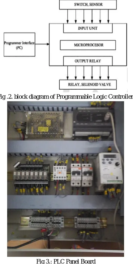
[image:4.612.196.419.117.559.2]Fig .2. block diagram of Programmable Logic Controller.
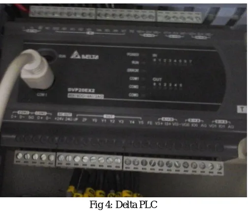
Fig 3.:PLC Panel Board
A. Advantages Of PLC
Very fast, Easy to change logic i.e. flexibility, Reliable due to absence of moving parts, Low power consumption Easy maintenance due to modular assembly, Facilities in fault finding and diagnostic ,Capable of handling of very complicated logic operations, Good documentation facilities, Easy to couple with the process computers, Analog signal handling and close loop control programming, Counter, timer and comparator can be programmed ,Ease operator interface due to colourographic and advisory system introduction.
B. Delta PLC
We are using DELTA PLC among three PLC’s because of following reason:
Technology (IJRASET)
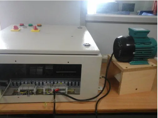
The PLC used here is a DELTA DVP-EX series manufactured by DELTA electronics. The EX series is the analog MPU with the lowest cost. It has got a total of 20 MPU points (8DI/6DO, 4AI/2AO). Apart from supporting digital input and output, the EX series has built-in multiple analog I/O channels and integrates a variety of communication protocols for constructing a complete control network. EX series is suitable for all kinds of small PLC applications.PLC is being used because of its many advantages when compared to a microcontroller. The response time of a PLC is much faster than a microcontroller. The PLC can handle multiple inputs simultaneously. The ladder logic program of a PLC is simpler and less time consuming than a program developed for a microcontroller.
[image:5.612.181.433.245.462.2]DELTA’s PLC DVP Series has main processing units and extension units. The main processing units offer 14-60 points and the extension units offer 8-32 points. The maximum input/output can be extended up to 128 points. It also can be used on applications according to INPUT/OUTPUT points, power sources, output modules, digital/analog exchanges (A/D & D/A converter). In addition, DVP SS Series has the special modules (AD/DA/PT/TC/XA) used for extending its functions and the maximum special modules can be extended up to 8 units.
Fig 4: Delta PLC
III. CONTROL OF THREE PHASE INDUCTION MOTOR
Various automation processes in the industry need control of AC induction motors using AC drives. Presented here is a robust system for switching on/off, varying the speed and direction of rotation of an industrial 3-phase induction motor using VFD and PLC. We use here Delta AC motor drive for its operation.
An electrical motor is an electromechanical device that converts electrical energy into mechanical energy. In case of 3-phase AC operation, the most-widely-used motor is the 3-phase induction motor as this type of motor does not require any starting device, being a self-starting motor. Often in the industry, need arises for controlling the speed of a 3-phase induction motor. Delta’s AC motor drives are able to efficiently control motor speed, improve machine automation and save energy. Each drive in its variable frequency drive (VFD) series is designed to meet specific application needs.
AC drives accurately control torque, smoothly handle increased load and provide numerous custom control and configuration operating modes. A VFD can be used to vary speed, direction and other parameters of a 3-phase motor. We use the 2-wire method for controlling the speed and direction of the motor.
Delta VFD-L is a sensor-less vector micro AC drive. Its compact design is ideal for small- and medium horsepower applications. L drive is designed to provide an ultra-low-noise operation and includes several innovative technologies that reduce interference.
A. Over Voltage Protection:
Technology (IJRASET)
otherwise started in the data sheets.
Electric motors are designed to operate within a specific voltage range, and any voltage outside that range will cause problems that shorten the service life of the motor. Under-voltage makes the motor draw a higher current, to be able to keep up with the load. Over time, this damages the motor and it also causes the inrush current to be higher.
Over-voltage saturates the ferromagnetic cores, which also increases the line current.Motors are normally equipped with a protection circuit which immediately disconnects the equipment if the voltage falls outside the range the motor is designed for.
B. Hardware implementation
[image:6.612.181.433.222.410.2]Hardware implementation for controlling and protection of three phase induction motor requires a 0.37KW/1410r/min Three phase Induction Motor, Delta PLC a dc voltage sensor with rating of 25v,a diode rectifier of rating 24v which converts ac voltage to dc voltage.
Fig 5 :Hardware setup for controlling of three phase induction motor.
Fig 6: Hardware Setup For Over Voltage Protection Of Three Phase Induction Motor
C. Developed Software
Technology (IJRASET)
programming method. The PLC system provides a design environment in the form of software tools running on a host computer terminal that allows LADs to be developed, verified, tested, and diagnosed. First, the high-level program is written in LADs. The LAD is then converted to binary instruction codes, so that they can be stored in RAM or erasable programmable read-only memory (EPROM). Each successive instruction is decoded and executed by the CPU. The function of the CPU is to control the operation of memory and I/O components and to process data according to the program. Each input and output connection point on a PLC has an address used to identify the I/O bit.
WPL Soft is a program-editing software made for the Delta DVP-PLC series used under WINDOWS. Except for general program planning and other general functions (e.g. cut, paste, copy, multi-windows, etc.) of WINDOWS, WPL Soft, in addition, has provided various English commentary-editing and other special functions (e.g. survey and edit the listed register, the setup, the data readout, the file saving, and monitor and set up diagrams of various contacts, etc.). Inorder to control induction motor we are using VFD and PLC ladder logic. To control the direction of three phase induction motor using VFD & PLC ladder logic.
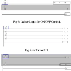
There are two contacts, M0 and M1. Whenever M0 is closed, VFD goes into run mode. If it is open, there is no rotation of the motor. M1 decides the direction of rotation. If M1 is open, it rotates in forward direction; if closed, in reverse direction.
[image:7.612.188.425.273.345.2]Now direction of induction motor is controlled using PLC ladder logic. Ladder logic is done in WPL Soft 2.41 Version.
[image:7.612.176.427.377.629.2]Fig 5: Ladder Logic for direction control. For ON/OFF control of three phase induction motor is done using VFD and PLC ladder logic.
Fig 6: Ladder Logic for ON/OFF Control.
Fig 7: motor control.
Fig8: overvoltage control
IV. RESULTS
Technology (IJRASET)
TABLE I
INPUT VOLTAGE OUTPUT VOLTAGE(DC)
230V 3.66V
230V 3.43V
At this particular output voltage motor will stop running by doing that motor will be protected from further damage control.
V. CONCLUSION
In this paper, Successful experimental results were obtained from the previously described scheme indicating that the PLC can be used in automated systems with an induction motor. By automation we can improve the productivity in the industry. We continuously monitor the state of input devices and make the decision based upon a custom program to control the state devices connected as output. The monitoring control system of the induction motor driven by VFD and controlled by PLC proves its high accuracy in speed regulation at constant-speed-variable-load operation. The PLC proved to be a versatile and efficient control tool in industrial electric drives applications. The effectiveness of the PLC-based control software is satisfactory up to 94% of the synchronous speed.
VI. FUTURE SCOPE
Expansion for this project can be done by extension of analog quantities like over current protection, thermal protection.By connecting required number of electrical devices, it can extend to develop the SCADA system and those types of systems are more reliable.
REFERENCES
[1] M. Peltola, “Slip of ac induction motors and how to minimize it,” ABB Drives Press Releases Technical Paper, ABB, New Berlin, 2003, pp. 1–7.
[2] Programmable Logic Controller, ―”An Automation Technique For Protection Of Induction Motor”ǁ Publish By International Research Journal Of Sustainable Science & Engg.
[3] ”Text Book of Electrical Technology in S.I units “by B.L.Theraja
[4] John W, Web, Ronald A.Reis “Programmable Logic Controllers Principles and Applications”.
[5] Maria G. Ioannides, “Design and Implementation Of Plc-Based Monitoring Control System For Induction Motor,” IEEETransactions On Energy Conversion, Vol. 19, No. 3, September 2004.