2018 International Conference on Modeling, Simulation and Analysis (ICMSA 2018) ISBN: 978-1-60595-544-5
6DOF Missile Trajectory Simulation Using Reusable Frame and Models
Jing ZHAO
1,2,*, Hua-bing WANG
1, Shen-shen WANG
2and Huan-yao DAI
11
State Key Laboratory of Complex Electromagnetic Environment Effects on Electronics and Information System (CEMEE), Luoyang, China
2
Key Lab of Complex Aviation System Simulation, Beijing, 100076, China *Corresponding author
Keywords: 6DOF, Trajectory simulation, Reusable design, Model frame, Design patterns.
Abstract. A reusable frame and appropriate models are designed for six degree of freedom (6DOF) missile trajectory simulation. The importance of establishing trajectory simulation model in missile design and experiment is described at first. Guidance Navigation and Control (GNC) loop as the core component in missile is discussed with emphasis on performance limitations. Design Patterns (DP) in software engineering are utilized to accomplish module partition. Reusable design is conducted in a two-step process: frame design and models design. This method can improve design productivity and shorten design circle as its reusable frame and relevant models can applied to many kinds of missiles without major revisions. An air defense scenario is designed to validate the proposed model frame. The 6DOF trajectory simulation results are obtained. Results show that the method offers an effective and practical way to design parameters and evaluate performance of missile.
Introduction
Missile as one kind of precision guided weapon is getting increasingly significant during modern warfare [1]. To solve the complexity of multidisciplinary design optimization (MDO), lots of factors coupled of missile system need to be investigated based on the sensitivity analysis [2]. A variety of methods can be used, as theoretical analysis model, analytical model, hardware-in-the-loop (HWIL) tests and field tests. Among these methods, modern synthetic simulation plays an important role in design parameters and evaluates performance of missile because of its lower cost and repeatability. Six degree of freedom (6DOF) refers to the displacement of a rigid body in three-dimensional space
[3]. Specifically, the body is free to move forward/backward, up/down, left/right with rotation about
three perpendicular axes, often termed pitch, yaw and roll. 6DOF trajectory simulation as an effective and practical way is getting extensive attention. Due to the complexity of MDO as well as diversity of missile types, 6DOF trajectory simulation usually could not easily conduct.
In this paper, a reusable frame and appropriate models are well designed to solve this problem. A two-step process is proposed with emphasis on reusable design. A typical scenario is also designed for further validation and demonstration.
Trajectory Simulation
Missile GNC Loop
Guidance navigation and control (GNC) loop is the core of missile system. Take the surface-to-air missile (SAM) for example, the terminal phase of SAM engagement puts forward a high requirement on its GNC loop, depicted in Fig. 1, as one has to take several key factors into account including target high-speed, low-altitude, stealth (low RCS), unknown maneuver, onboard ECMs, fin-angle demand, autopilot tag, missile body aerodynamic characteristics [2].
attitude, a control command unit generate control instruction transferred to the following execution device, i.e. a tail fin to stabilize body while guide the missile to the designated target according to the input acceleration demand. Tail fin responses the steering angle commands to achieve the actual fin angles. Once fin angles are changed, the interceptor SAM is aerodynamically controlled, and a 6DOF closed loop missile trajectory simulation is finally accomplished.
Aerodymanics
Seeker Guidance Law Control Command
Fin Target t arget mot ion
missile mot ion
M 2T mot ion
accelerat ion demand
missile flying st at us
[image:2.595.139.462.148.286.2]fin- angle demmand fin angles achieved
Figure 1. SAM’s GNC loop.
Design Pattern
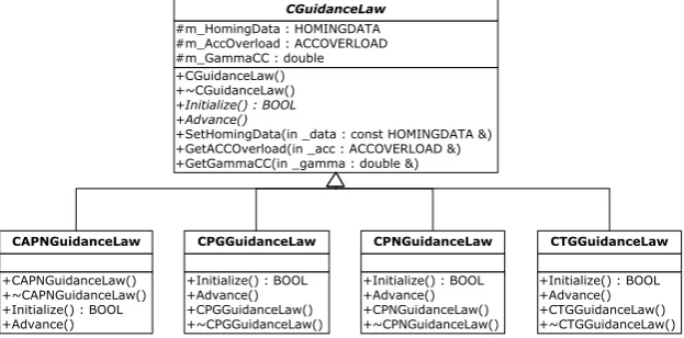
To conduct 6DOF trajectory simulation, modern simulation techniques could be utilized to help improve design productivity and shorten design circle. Design pattern (DP) in software architecture is a formal way of documenting a solution to a design problem in a particular field of expertise [4]. Take the Strategy Pattern (also known as the policy pattern) for example; it is a design pattern that enables an algorithm’s behavior to be selected at runtime, and it lets the algorithm vary independently from client that uses it. As an example, strategy pattern can be used in missile guidance law design, as a variety of law could be selected by clients, as proportional navigation (PN), augmented proportional navigation (APN) shown in Fig. 2. Each pattern describes a problem that occurs over and over again in practice, and then depicts the core of solution to that problem. We can use this solution without ever doing it the same way twice. Accordingly, design productivity would improve drastically.
+CGuidanceLaw() +~CGuidanceLaw()
+Initialize() : BOOL +Advance()
+SetHomingData(in _data : const HOMINGDATA &) +GetACCOverload(in _acc : ACCOVERLOAD &) +GetGammaCC(in _gamma : double &) #m_HomingData : HOMINGDATA #m_AccOverload : ACCOVERLOAD #m_GammaCC : double
CGuidanceLaw
+CAPNGuidanceLaw() +~CAPNGuidanceLaw() +Initialize() : BOOL +Advance()
CAPNGuidanceLaw
+Initialize() : BOOL +Advance() +CPGGuidanceLaw() +~CPGGuidanceLaw()
CPGGuidanceLaw
+Initialize() : BOOL +Advance() +CPNGuidanceLaw() +~CPNGuidanceLaw()
CPNGuidanceLaw
+Initialize() : BOOL +Advance() +CTGGuidanceLaw() +~CTGGuidanceLaw()
CTGGuidanceLaw
Figure 2. Strategy pattern used in guidance law design.
Reusable Frame Design
Functional Requirement and Interfaces
[image:2.595.142.454.484.638.2]box perspective only; the only interactions shown are those between this model and the system actors. Accordingly, we list the functional requirements and relevant interfaces as below.
Initialization. The initialization process should be conducted as soon as a missile object created. Those initialization parameters include missile mass, size, initial flight status, aerodynamic feature, thrust data, rotation inertia, mass decreasing rate, flight range, etc.
Presetting. Missile as one kind of precision guided weapon needs launch data presetting, such as initial body position, velocity, heading, attitude and selected target information (for detection use).
Command Input. During the phase of terminal guidance (as homing guidance), seeker outputs are converted into three axes acceleration demands to guide the missile to the designated target. While in the phase of midcourse flight (as remote command guidance), command from ground control station is sent to missile for the flight attitude control. After responding to the input instructions, the missile is aerodynamically controlled, and closed loop missile trajectory simulation can finally accomplish.
Flight Solution. Flight solution is the main task of simulation model. Those rotation angles and linear displacements of missile body are solved corresponding to the input instructions.
Status Inquiry. By inquiring trajectory simulation model, one can obtain the real-time flight status as well as missile internal status, including acceleration demands, control instruction, steering angle commands, actual fin angles and onboard navigation outputs.
Termination. A fuse module in missile model can be used to sense M2T motion in near-filed and thus complete the final detonation decision; missile trajectory simulation would then terminate.
Configuration Items
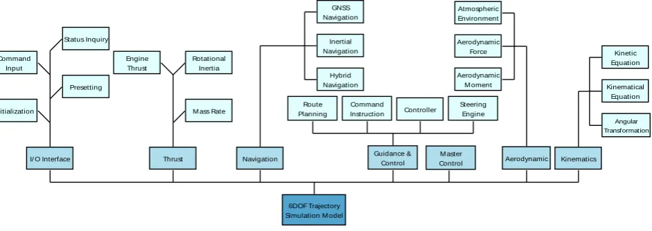
[image:3.595.66.537.444.611.2]By modularizing model design, one can separate content from structural presentation. Some other basic design principles as simplicity, tolerance and decentralization are also followed. As depicted in
Fig. 3, missile model is divided into seven main parts (sub-systems), including I/O interface, thrust,
navigation, guidance & control, aerodynamic, kinematics and master control.
6DOF Trajectory Simulation M odel
Guidance & Control
I/ O Interface Navigation
Steering Engine Route
Planning
Command Instruction
Thrust Command
Input
Presetting
Initialization
Status Inquiry
Kinematics Aerodynamic
Rotational Inertia Engine
Thrust
M ass Rate
GNSS Navigation
Inertial Navigation
Hybrid Navigation
Controller
M aster Control
Atmospheric Environment
Aerodynamic Force
Aerodynamic M oment
Kinetic Equation
Kinematical Equation
Angular Transformation
Figure 3. Configuration items.
I/O Interface. It is designed to execute input/output data exchange, including model initialization, command input, missile status inquiry, etc.
Thrust. It is divided into three parts: engine thrust, rotation inertia and mass decreasing rate.
Navigation. This item is designed to obtain missile real-time flight navigation solution by using onboard navigation apparatus, as GNSS, inertial navigation system (INS) and their integration.
Guidance & Control. It is the core of missile model. Command inputs are converted to demands of acceleration, then transferred to control instruction fed to the following execution device. Tail fin responses the steering angle commands to achieve the actual fin angles.
Kinematics. It utilizes aerodynamics characteristic to solve real-time missile flying status.
Master Control. As the center of simulation model, it coordinates all other items operation and finishes missile status transition and other tasks.
Reusable Modeling
UML Diagram
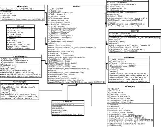
After designing a reusable frame for trajectory simulation, appropriate models are also constructed with emphasis on their reusability and extensibility. A variety of patterns are taken into account, as Strategy, Prototype, Factory, Builder, Singleton, Bridge, Composite, Decorator. To provide sufficient detail to allow a clear understanding of principles, the UML class diagram is depicted in Fig. 4, where
Builder Pattern is utilized to enable different sub-system configuration and Façade Pattern to clarify application programming interface (API) of missile model.
+ARMDLL() +ARMDLL(in uSN : USHORT)
+ARMDLL(in uSN : USHORT, in _basic : const ARMBASIC &) +~ARMDLL()
+SetARMSN(in _uSN : USHORT) +GetARMSN() : USHORT +GetARMState() : FLIGHTSTATE +SetARMBasic(in _Basic : const ARMBASIC &) +GetARMBasic() : ARMBASIC +GetARMTComm() : double +SetARMTComm(in _time : double) +GetCurSimTime() : double +Initialize(in XS : double*) : BOOL +SetSeekerMeas(in _mes : const SEEKERMEAS &) +Advance()
+GetARMMotion(in _arm : ARMPROPERTY &) +GetMotionData(in data : double*) +GetARMRCS() : double #UpdateMotionState(in XS : double*) #UpdateRealMotion(in _state : NAVSTATE &)
#UpdateIMUMeas(in _imu : IMUMEAS &, in _nav : const NAVSTATE &) -m_uSN : USHORT
-m_bValid : bool -m_FlightState : FLIGHTSTATE -m_Basic : ARMBASIC -m_dTcomm : double -m_dCurSimTime : double -m_nAdvanceFrame : int -m_bIsTerGuidance : BOOL -m_RoutePlan : CRoutePlan * -m_Thrust : CThrust * -m_Aerodynamic : CAerodynamics * -m_LayoutFlight : CLayoutFlight * -m_Guidance : CGuidance * -m_Control : CControl * -m_Navigation : CNavigation * -m_Kinematic : CKinematic * -m_Ctrl : CMainCtrl * -m_SeekerMeas : SEEKERMEAS
ARMDLL
+CRoutePlan() +~CRoutePlan() +Initialize() : BOOL +Advance()
+GetPlanRoute(in _trace : vector<LAYOUTTRACE> &) -m_vecLayout : vector<LAYOUTTRACE>
CRoutePlan
+CThrust() +~CThrust() +Initialize() : BOOL +Advance(in _time : double) +GetCurThrust() : double +GetCurMassRate() : double -m_MassRate : CMassDecrease * -m_nCount : int -m_dThrust : double -pTIndex : double * -pThrust : double *
CThrust
+CAerodynamics() +~CAerodynamics() +Initialize() : BOOL +Advance(in _fin : const FINANGLE &) +GetAeroForce(in _force : AEROFORCE &) +GetAeroMoment(in _moment : AEROMOMENT &) +GetRotorInertia(in _inertia : ROTORINERTIA &) -m_AeroForce : CAeroForce * -m_AeroMoment : CAeroMoment * -m_RotorInertia : CRotorInertia *
CAerodynamics
+CLayoutFlight(in _law : CGuidanceLaw*) +~CLayoutFlight() +Initialize() : BOOL +Advance()
+SetIMUMeas(in _nav : const NAVSTATE &) +GetACCOverload(in _acc : ACCOVERLOAD &) +GetGammaCC(in _gamma : double &) -m_GuidanceLaw : CGuidanceLaw *
CLayoutFlight
+CGuidance(in _law : CGuidanceLaw*) +~CGuidance() +Initialize() : BOOL
+SetSeekerMeas(in _mes : const SEEKERMEAS &) +SetIMUMeas(in _nav : const NAVSTATE &) +Advance()
+GetACCOverload(in _acc : ACCOVERLOAD &) +GetGammaCC(in _gamma : double &) -m_Fusion : CFusionFilter * -m_GuidanceLaw : CGuidanceLaw * -m_nProdFrame : int -m_nSeekerUpdate : int -m_nCtrlUpdate : int
CGuidance
+CControl(in _law : CControlLaw*, in _ctrl : CControlSurface*) +~CControl()
+Initialize() : BOOL +Advance()
+SetACCOverload(in _acc : const ACCOVERLOAD &) +SetGammaCC(in _gamma : double) +SetIMUMeas(in _mea : const IMUMEAS &) +GetFinAngle(in _fin : FINANGLE &) -m_CtrlLaw : CControlLaw * -m_CtrlSurface : CControlSurface *
CControl
+CNavigation(in _gnss : CGNSS*) +~CNavigation() +Initialize() : BOOL +Advance()
+SetINSNavErr(in _err : const INSNAVERR &) +SetGNSSNavErr(in _err : const GNSSNAVERR &) +SetRealMotion(in _nav : const NAVSTATE &) +GetMeasMotion(in _state : NAVSTATE &) #SetNavErrData(in _est : const ESTNAVERR &) -m_SINS : CSINS *
-m_GNSS : CGNSS * -m_Hybrid : CHybridNavigation *
CNavigation
+CKinematic() +~CKinematic() +Initialize() : BOOL +Advance(in _step : double) +SetThrust(in _thrust : double) +SetMassRate(in _rate : double) +SetInertia(in _rot : const ROTORINERTIA &) +SetAeroForce(in _force : const AEROFORCE &) +SetAeroMoment(in _moment : const AEROMOMENT &) +GetMotionData(in data : double*) #StateDery(in dXS : double*, in XS : double*) #SetMotionState()
-XS : double * -dXS : double * -m_Thrust : double -m_MassRate : double -m_Inertia : ROTORINERTIA -m_AeroForce : AEROFORCE -m_AeroMoment : AEROMOMENT -m_LaunchPos : GEOG_COORD
CKinematic
+CMainCtrl() +~CMainCtrl() +Initialize() : BOOL +Advance()
+GetTerGuidanceFlag(in _flag : BOOL) -m_bIsTerGuidance : BOOL
[image:4.595.165.431.268.477.2]CMainCtrl
Figure 4. UML class diagram of missile model.
Guidance & Control
As the core of missile model, guidance & control module has to be well designed. Strategy pattern
is utilized to enable model extensibility, i.e. system actors can easily change algorithm’s behavior to fit different missile types, as shown in Fig. 5. Note that the guidance law module is designed to a base class to help create those derived classes, as PN, APN, PG and TG. Other advanced guidance law, as OGL and OSMG can also be used to fit in user’s new needs. Similarly, control law item is a base class to allow the creation of derived class, as slide-to-turn (STT), bank-to-turn (BTT) and PID law. These control laws guide missile to the designated target while stabilize the missile body.
+CGuidance(in _law : CGuidanceLaw*) +~CGuidance() +Initialize() : BOOL
+SetSeekerMeas(in _mes : const SEEKERMEAS &) +SetIMUMeas(in _nav : const NAVSTATE &) +Advance()
+GetACCOverload(in _acc : ACCOVERLOAD &) +GetGammaCC(in _gamma : double &) -m_Fusion : CFusionFilter * -m_GuidanceLaw : CGuidanceLaw * -m_nProdFrame : int -m_nSeekerUpdate : int -m_nCtrlUpdate : int
CGuidance
+CFusionFilter() +~CFusionFilter() +Initialize(in dMesNoise : double) : BOOL +SetSeekerMeas(in _mes : const SEEKERMEAS &) +SetIMUMeas(in _nav : const NAVSTATE &) +Advance()
+Prediction() +Update()
+GetLOSRate(in _rate : LOSRATE &) +GetFiterOut(in data : double*) +GetSteadyFlag() : int -m_SeekerMeas : SEEKERMEAS -m_NavState : NAVSTATE -PHI : CMatrix -Q : CMatrix -H : CMatrix -RR : CMatrix -M : CMatrix -P : CMatrix -Zn : CMatrix -IM : CMatrix -IS : CMatrix -K : CMatrix -sigma : double -bIsInverse : BOOL -nFilterState : int -dAngleEstErr : double -dRateEstErr : double -nFrame : int
CFusionFilter
+CGuidanceLaw() +~CGuidanceLaw()
+Initialize() : BOOL +Advance()
+SetHomingData(in _data : const HOMINGDATA &) +GetACCOverload(in _acc : ACCOVERLOAD &) +GetGammaCC(in _gamma : double &) +SetUpdateFlag(in _seeker : BOOL, in _ctrl : BOOL) #m_HomingData : HOMINGDATA #m_AccOverload : ACCOVERLOAD #m_GammaCC : double #m_bIsSeekerUpdate : BOOL #m_bIsControlUpdate : BOOL CGuidanceLaw
+CAPNGuidanceLaw() +~CAPNGuidanceLaw() +Initialize() : BOOL +Advance()
CAPNGuidanceLaw
+CPGGuidanceLaw() +~CPGGuidanceLaw() -m_nCurTraIndex : int CPGGuidanceLaw
+CPNGuidanceLaw() +~CPNGuidanceLaw() -m_dPPNCoeff : double -m_dTg : double -m_dTad : double -m_dMNytC : double -m_dMNztC : double -m_dNyC : double -m_dNzC : double CPNGuidanceLaw
+CTGGuidanceLaw() +~CTGGuidanceLaw()
CTGGuidanceLaw
[image:4.595.178.421.640.755.2]Simulation Test
A typical air defense scenario is designed. Note that we only focus on the terminal guidance phase of
engagement; the midcourse guidance is not considered. Some key experiment parameters are listed in
[image:5.595.91.505.155.296.2]Table 1, and their values and units are also described.
Table 1. Table headings.
Parameters Values Units Notes
1 initial target position (7000, 1000, 0) m, m, m
X, Y, Z-axis compoment in the reference frame, i,e, local level frame (LLF)
2 initial target velocity (200, 0, 0) m/s, m/s, m/s 3 initial missile position (0, 200, 400) m, m, m 4 initial missile velocity (600, 0, 0) m/s, m/s, m/s
5 initial missile attitude (0, 0, 0) °, °, ° yaw, pitch, roll, respectively 6 effective navigation ratio 4.5 -- used in APN guidance law 7 trajectory update period 10 ms same as seeker update period
The 6DOF trajectory simulation is finished as below. Real-time missile and target motion data is sent to a functional seeker model to extract M2T relative motion measurements, i.e. range, range rate, line-of-sight (LOS) angles and their rates. After inertial angular rates of LOS are estimated in seeker model, homing guidance is then accomplished by the APN law. The fin-angle instruction is generated in BTT control unit to guide SAM interceptor to target while stabilize missile body. Tail fins response the angle command; actual fin angles in three axes is achieved. SAM is aerodynamically controlled, and a 6-DOF closed loop trajectory simulation is finally finished.
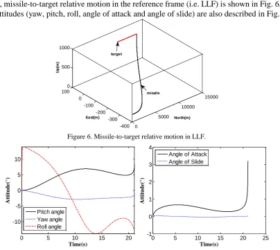
Firstly, missile-to-target relative motion in the reference frame (i.e. LLF) is shown in Fig. 6, where missile attitudes (yaw, pitch, roll, angle of attack and angle of slide) are also described in Fig. 7.
0
5000
10000
15000
-400 -300 -200 -100 0 100
0 500 1000
North(m) East(m)
U
p
(m
)
[image:5.595.100.505.410.771.2]missile target
Figure 6. Missile-to-target relative motion in LLF.
0 5 10 15 20
-10 -5 0 5 10
Time(s)
A
tt
it
u
d
e
(°
)
Pitch angle Yaw angle Roll angle
0 5 10 15 20 25
-1 0 1 2 3 4
Time(s)
A
tt
it
u
d
e
(°
)
[image:5.595.110.489.607.767.2]Angle of Attack Angle of Slide
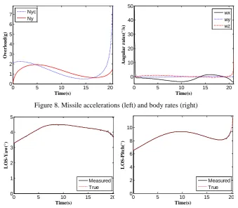
The command and actually achieved missile overloads in azimuth channel are compared in Fig. 8. The impact made by autopilot lag and missile aerodynamic characteristics on actual overload can be reflected. Body rates in three axes are also shown in Fig.8. These measured LOS angles are compared with true values in Fig. 9, where good angle estimation performance of seeker model is shown.
0 5 10 15 20
0 1 2 3 4 5 6 7
Time(s)
O
ve
r
load
(g)
Nyc Ny
0 5 10 15 20
0 10 20 30 40 50
Time(s)
A
n
gu
lar
r
at
e
s(
°/
s)
[image:6.595.132.472.130.426.2]wx wy wz
Figure 8. Missile accelerations (left) and body rates (right)
0 5 10 15 20
0 1 2 3 4 5
Time(s)
L
O
S
-Y
aw
(°
)
Measured True
0 5 10 15 20
0 2 4 6 8 10
Time(s)
L
O
S
-P
it
c
h
(°
)
Measured True
Figure 9. Line-of-sight angle measurements (left: yaw, right: pitch).
Summary
A reusable frame and appropriate models are designed for 6DOF missile trajectory simulation thus to offer an effective and practical way to design parameters and evaluate performance of missile system. A study will follow up in reusable model verification and its application.
Acknowledgement
This research was supported by the CEMEE research project “Reusable Design Methodology of Electronic and Information System Simulation Model” (No. CEMEE2017K0302A).
References
[1] Vathsal S, Sarkar A K. Current Trends in Tactical Missile Guidance [J]. Defence Science
Journal, 2005, 55(3):265-280.
[2] Pittman W, Powell R, Pittman W, et al. Trends in tactical missile guidance and control
strategy and program formulation[C]// Defense and Space Programs Conference and Exhibit - Critical Defense and Space Programs for the Future. 2013.
[3] Hua J, Meng Y H, Dai J H. Modeling and Simulation of Six-Degrees-of-Freedom (6DOF)
Trajectory of Missile with Wrap Around Fins in Disturbance of Wind Field [J]. Journal of System Simulation, 2007.
[4] Moller B, Antelius F, Johansson M, et al. Building Scalable Distributed Simulations: Design