2018 3rd International Conference on Information Technology and Industrial Automation (ICITIA 2018) ISBN: 978-1-60595-607-7
CFD-Based Numerical Simulation for Helical
Heating Pipes
Shouwen Pang, Shaojun Zhang, Mingyu Wang and Bingbing Liu
ABSTRACT
For helical pipes, author builds their three-dimensional models, identifies their boundary conditions and makes CFD-based simulating calculation for their heat transfer in this paper. Therefore, related theoretical guidance could be made for the design and application of helical heat exchanger by referring to the temperature-distribution and heat-transferring laws elicited from both contrastive analysis and calculation for internal/external flow and temperature distribution in helical heating pipes with different inner diameters and screw pitches.1
INTRODUCTION
In recent years, domestic and foreign scholars have done a lot of research on heat transfer enhancement of shell-and-tube heat exchangers. Various types of reinforced tubes have been developed by studying the heat transfer performance of light tubes. Spiral-bound tube heat exchangers relying on spiral tube heat transfer have been introduced into the domestic market from abroad in 2002. Among them, the spiral tube has already been in HVAC, due to its high heat transfer efficiency, convenient cleaning, compact structure, and easy processing and production. Many fields such as chemical industry, petroleum, metallurgy, and textile have been widely used and popularized, and they have attracted the attention of domestic HVAC experts and scholars. It can be seen that the research on the heat transfer law of spiral heating pipe has very important academic significance and engineering application value [1].
1
2r Rc 2 s p 1
[image:2.612.187.406.83.198.2]x x2 3 x B T N X x ( ) P x N r
Figure 1. Structure and the orthogonal coordinate of spiral tube.
TABLE I. THE HEAT EXCHANGE PIPE SIZE SPECIFIED(mm).
outer diameter 10 14 19 25 32 38
Wall thickness 1.5 2 2 2 2.5 2 3 2.5 3
TABLE II. STAINLESS STEEL HEAT PIPE WALL THICKNESS PRESCRIBED.
material standard Pipe diameter /mm thickness /mm
stainless steel
GB13296 ≥14-31 1.0-2.0
GB9948 >30-50
>2.0-3.0
GB/T14976 57
SPIRAL TUBE STRUCTURE AND ENHANCED HEAT TRANSFER PRINCIPLE
For spiral tube with constant curvature, the spiral orthogonal coordinate system proposed by Germano is used to establish the model. The structure of the spiral tube is shown in Figure 1. The parameters are mainly determined by the curvature ratio and the tensional ratio, wherein the curvature ratio is defined as [2]:
/ c
a R (1)
The definition of twist rate can be expressed as:
2 2 s C S p R p
[image:2.612.119.473.357.448.2]Where: a is the outer diameter of the spiral pipe; is the twist rate; Rc is the
radius of curvature of the spiral pipe; ps is the slope constant of the spiral pipe, used
to measure the pitchS2ps.
A three-dimensional physical model of the spiral heating tube was established using the workbench in ANSYS software. The ICEM module was used to perform the grid division. Then CFD pretreatment and post-treatment were used to perform numerical simulation and thermal analysis of each flow process. Helix related parameters are shown in TABLEI and TABLE II.
Using Workbench software to establish three-dimensional physical model of heat exchange tube, air space and hot water in the tube of each specification, and then import the model into ICEM for meshing. The mesh is divided into unstructured meshes and surface-to-body. Divide the method, the type of the mesh is Tetra/Mixed, checks the repair mesh finally, and trims the automatically generated mesh to improve the quality of the mesh. Figure 2 and Figure 3 show the meshing results of air and spiral tubes in the heat exchanger.
[image:3.612.206.380.323.401.2]Figure 2. The results of mesh generation for a change of air in the heat.
Figure 3. Spiral pipe mesh results.
BOUNDARY CONDITION SETTINGS
When using the standard k-ε model in CFD for spiral tube heat transfer calculation, the relevant boundary conditions need to be defined. The calculation domain, spiral tube inner and outer boundary conditions and wall boundary conditions are defined as follows [3]:
The ideal air is taken as the outer fluid area of the spiral tube, and the high-temperature hot water is used as the fluid field in the spiral tube. The domain motion is set to the stationary state, the heat transfer model is the enthalpy model, and the turbulence model is selected as the k-Epsilon model.
2) Spiral pipe inner and outer boundary conditions
Spiral tube high temperature hot water inlet temperature T = 80 °C; speed u = 0.1m / s; spiral outside the air inlet temperature T = 5 °C; speed u = 0.05m / s, the fluid flow is subsonic. The boundary condition of the free flow outlet of the fluid inside and outside the spiral pipe is set as the pressure outlet, and the relative pressure is set to 0 Pa.
3) Wall boundary conditions
The spiral tube is divided into two contact surfaces, the inner contact surface is in contact with the hot water in the tube, and the outer contact surface is in contact with the air to be heated. The thermal boundary condition is set as convective heat exchange, and the wall surface of the tube is set as a non-slip boundary. Smooth, in which the convection heat transfer coefficient on the hot water side is 1000W/ (m2•K), the hot water side temperature is 80°C; the convection heat transfer coefficient on the air side is 10W/ (m2•K), and the air side temperature is 5°C.
INFLUENCE OF KEY PARAMETERS OF SPIRAL HEATING PIPE ON THE TRANSFER LAW OF FLUID INSIDE/OUTSIDE THE PIPE
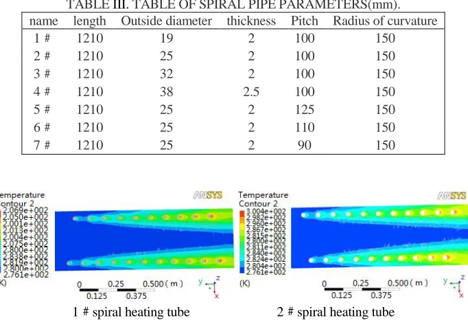
According to the curvature ratio and torsion calculation formula, in this study, the curvature ratio is represented by the outer diameter of the spiral heating tube as a variable, and the pitch of the spiral heating tube is used as a variable to reflect the change in the tensional rate, and a different outer diameter is established. The three-dimensional model of the 7 spiral heat exchangers with different pitches is shown in TABLE 3 for the parameters of each spiral tube [4].
Simulation Results of Heat Transfer Law outside the Spiral Heating Tube
Through the numerical simulation of flow field distribution, temperature distribution and heat transfer of the spiral heating tube, it is concluded that the heat transfer effect is enhanced with the increase of the outer diameter of the spiral heating tube under the same radius of curvature. There are two reasons: On the one hand, because the increase in the outer diameter of the pipe directly increases the heat transfer area, which enhances the heat transfer. On the other hand, the larger the outer diameter of the tube, the greater the curvature ratio and the greater the Dean number, the greater the spoiler effect outside the spiral heating tube, and the more frequent and sufficient the heat exchange between the fluid on the outside of the tube and the fluid on the tube side. The heat transfer effect is also enhanced. Therefore, as the outer diameter of the spiral heating tube increases, the heat transfer effect of the spiral heating tube will continue to increase.
TABLE III. TABLE OF SPIRAL PIPE PARAMETERS(mm). name length Outside diameter thickness Pitch Radius of curvature
1﹟ 1210 19 2 100 150
2﹟ 1210 25 2 100 150
3﹟ 1210 32 2 100 150
4﹟ 1210 38 2.5 100 150
5﹟ 1210 25 2 125 150
6﹟ 1210 25 2 110 150
7﹟ 1210 25 2 90 150
1﹟spiral heating tube 2﹟spiral heating tube
Figure 4. The axial temperature distribution of air flow.
[image:5.612.127.468.278.516.2]2﹟spiral heating tube 7 # spiral heating tube
[image:5.612.150.442.567.659.2]Results of Simulation of The Heat Transfer Law of Spiral Heating Pipe Outside The Spiral Heating Pipe
Figure 5 shows the temperature distribution of the air outside the 2 # and 7 # spiral heating tubes with different pitch spirals.
It can be seen that during the simulation of the outside air of the 2# and 7# spiral heating pipes, the temperature gradually increases along the air flow direction, and the heat exchange intensity near the spiral heating pipe boundary is relatively high, resulting in temperature at the edges is higher than temperature at the center. With the reduction of the pitch, the heat transfer effect is enhanced. Because with the reduction of the pitch, the turbulent effect caused by the spiral heating tube rotating structure will increase, so that the outside air of the tube is fully mixed and heat exchange is performed, so that the heat transfer effect is improved [6].
Through the simulation results of the heat transfer conditions and the temperature distribution of four spiral heating tubes with the same outer diameter and different pitches, it is concluded that with the increase of the spiral heating tube pitch, the turbulence outside the spiral tube increases with the constant Rc. To the extent that the degree of heat transfer between the spiral pipe fluids is reduced, the heat transfer effect is reduced.
CONCLUSIONS
By using the computational fluid dynamics method, the outside temperature distribution of the shell-and-tube heat exchanger tubes with spiral heating tubes with different parameter sizes was numerically simulated using CFX software, and the temperature distribution and heat transfer rules outside the spiral heating tubes were obtained. Conclusions are as below:
1) For spiral heating tubes with different curvature ratios, the outer diameter of the spiral tube is used as a variable. With the increase of the outer diameter of the spiral heating tube, the heat transfer effect is enhanced.
2) For spiral heating tubes with different parameters of different tensional ratios, the pitch is a variable. With the increase of the pitch of the spiral heating tube, the heat transfer effect is weakened.
REFERENCES
1. M. Mansour, G. Janiga, K. D. P. Nigam et al. 2018. “Numerical Study of Heat Transfer and Thermal Homogenization in a Helical Reactor,”Chemical Engineering Science. 177: 369-379. 2. Wang Xiaoyuan, Wang Yinfeng, Wang Zhi. et al. 2018. “Simulation-Based Analysis of a Ground
3. N. Demesa, J.A. Hernández, J. Siqueiros et al. 2018. “Heat Transfer Coefficients for Helical Components inside an Absorption Heat Transformer,” International Journal of Heat and Mass Transfer. 120: 342-349.
4. Hessam Mirgolbabaei. 2018. “Numerical Investigation of Vertical helically Coiled Tube Heat Exchangers Thermal Performance,” Applied Thermal Engineering, 136: 252-259.
5. Simin Wang, Guanping Jian, Juan Xiao. 2018. “Fluid-Thermal-Structural Analysis and Structural Optimization of Spiral-Wound Heat Exchanger,” International Communications in Heat and Mass Transfer. 95: 42-52.