Published online December 30, 2014 (http://www.sciencepublishinggroup.com/j/ijepe) doi: 10.11648/j.ijepe.20140306.13
ISSN: 2326-957X (Print); ISSN: 2326-960X (Online)
Heating and cooling hybrid system and method for its
calculation and design
Zohrab Melikyan
Armenia National University of Architecture and Construction, HVAC and Energy, Yerevan, Armenia
Email address:
To cite this article:
Zohrab Melikyan. Heating and Cooling Hybrid System and Method for Its Calculation and Design. International Journal of Energy and Power
Engineering. Vol. 3, No. 6, 2014, pp. 296-307. doi: 10.11648/j.ijepe.20140306.13
Abstract:
In this article newly developed heating and cooling hybrid system is discussed. The system combines a heat pump, heating boiler and solar air heater. Low temperature source of heat pump is a gas mixture composed of waste warm gases, like inside used ventilation air, flue gases of heating boiler (smock), as well as outside air, heated in solar air heater. The evaporator of heat pump is installed in waste warm gases mixing chamber, aiming at avoiding the main disadvantage of ordinary air sourced heat pump, in case of which the evaporator surface in wintertime is covered with ice crust that obstructs movement of air through the evaporator of heat pump. To solve the problem it is suggested to create a mixture of waste warm gases gathered in a gas mixing chamber and serving as heat source. A method for calculation and design of the new system was developed for both winter heating and summer cooling of a building. The energy and economic investigation based on mathematical model proved rather high cost effectiveness and energy efficiency of developed heating and cooling hybrid system.Keywords:
Hybrid System, Heat Pump, Heating Boiler, Solar Air Heater, Gases Mixing Chamber, Winter Heating,Summer Cooling, Cost Effectiveness, Energy Efficiency
1. Introduction
The new type hybrid system consists of heating boiler, heat pump, and lately developed solar air heater. As low temperature heat source of the heat pump, instead of outside air, is used a mixture of various warm waste gases, gathered from different parts of a building or surrounding objects and collected in a gas mixing chamber. The gas mixture comprises boiler’s smock; ventilation used air evacuated from the building and outside air, heated in solar air heater. The temperature of warm gases mixture is much higher, than the temperature of wintertime outside air. In fact, a new heating and cooling system is developed the heat pump of which uses artificially created low temperature heat source. The simplified version of such system was published in [4, 6].
2. Structure and Operation of Newly
Developed Heating and Cooling
Hybrid System
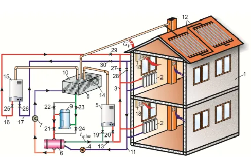
The scheme of the heating and cooling hybrid system is represented in the Fig.1.
1- building; 2-fan-coils of heating system; 3-heat carrier distribution stands and pipes; 4-variable speed water circulation pump; 5- heating boiler; 6-con-denser of heat pump; 7-throattling valve; 8- evaporator of heat pump, located in gas mixing chamber; 9-compressor of heat pump; 10-gas mixing chamber; 11- return pipe of used and cooled heat carrier; 12- solar air heater modules; 13- by-pass valve; 14-exhaust fan of gas mixing chamber; 15-separate boiler for heating of ventilation fresh air; 16-hot water supply pipe to the ventilation air heating equipment; 17- return water pipe from ventilation equipment; 18-ventilation air heating heat exchanger; 19, 20- valves; 21, 22, 23, 24 - bypass valves for reversing the refrigerant of heat pump; 25, 26-valves of separate boiler; 27, 28, 29, 30- valves of ventilation system.
In heating season the hybrid system operates in two regimes: 1) daytime - sunshine period of heating season, 2) cloudy and nighttime period of heating season. In summertime the system can operate for summertime cooling of building too.
3. Operation of the Hybrid System in
Daytime - Sunshine Periods of Heating
Season
In mentioned period the system operates in the following way (see Fig.1): from fan-coils (2) of the house’s heating system the used and cooled heating water at temperature tw.1
returns from fan-coils to the condenser (6) of heat pump where is partially heated up to an intermediate temperature tw.int. Then
the warmed water from condenser is forced into the boiler (5) where is heated from intermediate temperature tw.int up to final
temperature tw.2.Afterwards the hot water is supplied from the
boiler to fan-coils (2) where delivers heat to the air of inside space for covering the heating demand Qhd, kW of the house,
which can be calculated by the help of method published in [1, 2]. As a result, the temperature of the water in fan-coils drops from tw.2 to tw.1. In fact, the heating demand of the house
is shared between the boiler and heat pump. To provide higher energy efficiency of the whole system the heat pump should cover the major portion of heating demand. The portion of heating demand covered by boiler Qb in sunshine period is
determined by the following expression:
hd
b Q
Q =β (1)
where:
β
=0.4 – rate of heating demand portion covered by heating boiler in sunshine period.Heating demand portion covered by the heat pump is the following:
(
)
hdHP
Q
Q
=
1
−
β
(2)where:
(
1−β)
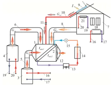
=0.6- portion of heating demand to be covered by the heat pump.To provide cost effectiveness of the whole hybrid system it is expedient to use air to air type simple and not expensive heat pump. However, in winter cold climate the evaporator of air-to-air heat pump can be covered by ice crust and can get out of order [1]. To escape freezing it is necessary to locate heat pump’s evaporator (8) in a warm gaseous environment. For this purpose, in a gas-mixing chamber (10) warm waste gases mixture is collected. To heating outside fresh ventilation air, a separate boiler (15) is applied. For better understanding of operation of the hybrid system, it is necessary to follow the construction and operation of gas mixing chamber connected with other main parts of the system. The scheme of construction and operation of gas mixing chamber represents the Fig.2.
1-gas mixing chamber; 2-heat pump’s evaporator; 3-heating boiler; 4-separate boiler for heating ventilation fresh air; 5, 6-chimneys of boilers; 7-building, 8-exhaust pipeline of ventilation used air; 9-solar air heater; 10-warm air supplying pipe from solar air heater; 11-valve; 12-gas mixture chamber exhaust fan; 13-compressor of heat pump; 14-condenser of heat pump; 15- throttling (expansion) valve; 16-heat carrier supplying pipeline; 17- heat carrier return pipeline; 18-fan-coil; 19-heat carrier return pipeline from ventilation system; 20-heat carrier supplying pipeline to ventilation system; 21-heat exchanger for heating ventilation fresh air.
Figure 2. Scheme of construction and operation of gas mixing chamber
connected with other main parts of the system
The gas-mixing chamber is an insulated metallic hermetic box (1), on the front edge of which the heating boiler’s (3) chimney outlet (5) is connected. On the upper horizontal edge of the chamber are connected building’s ventilation used air evacuation pipeline (8), supply pipeline (10) of solar air heater and separate boiler’s (4) chimney outlet (6). On the backside edge, an exhaust fan (12) is fixed for evacuating used and cooled gas mixture. In the mixing chamber, the evaporator (2) of the heat pump is located. Evaporator divides the mixing chamber in warm and cooled gases sections. Into warm gases section enter flue hot gas (smock) of boilers, exhaust warm ventilation air and outside air, warmed in solar air heater (9). In the mixing chamber, the gas mixture acquires a total thermal potential ΣQmix, kW consisted of thermal potentials of
separate gases. The thermal potential of each gas in the mixture Qgas.pot, kW is determined by the following
production:
i gas i gas i gas pot
gas G C t
Q . = . ⋅ . ⋅ . (3)
where:
Ggas.i – mass of each kind of gases, kg/s,
Cgas.i – specific heat of each kind of gases, kJ/kgoC ,
tgas.i - temperature of each kind of gases, oC.
The total thermal potential of gas mixture ΣQmix, kW in gas
mixing chamber is the following production:
.1 mix mix mix
mix G C t
Q = ⋅ ⋅
Σ (4)
where:
Gmix – total mass of all kinds of gases in the mixing chamber, kg/s,
Cmix – average specific heat of gases, kJ/kgoC ,
tmix.1 – temperature, acquired by the mixture of gases, oC.
mix mix
mix .1
mix
C
G
Q
t
⋅
Σ
=
(5)To determine the value of
tmix.1
should be found values ofGmix
andΣ
Qmix
of the gas mixture. For this purpose, first the values of massesGgas
, kg/s and thermal potentialsQpot
, kW of separate gases must be determined.4. Determination of Masses of Waste
Warm Gases Collected in Gas Mixing
Chamber
Mass of flue gas (smock)
Gsm
, kg/s produced by heating and separate boilers depend on portion of heating demand, covered by the heating boiler (Q
b=
β
Q
hd ) and also by heatQV
produced by separate boiler for heating whole quantity of ventilation fresh air, for replacing completely extracted used ventilation air from the building. Therefore the mass of smockGsm
, kg/s entering into gas mixing chamber should be determined by the following equation which takes into account that burning of 1m3 of natural gas produces 12m3 of flue gas [8]:gas b
V hd sm sm
Q
η
Q Q G
3600
12 +
=
ρ
β
(6a)where: the quantity of heat
QV
, kW, produced by separate boiler for heating of ventilation fresh air from outside temperaturetout
to inside air temperaturetin
is determined by the following formula:(
)
3600
9
20
⋅
−
⋅
⋅
⋅
⋅
=
air air in out Vt
t
C
n
b
a
Q
ρ
(6b)where:
ρsm - density of flue gas (smock), kg/m3,
ηb – COP of boilers,
Qgas - specific calorific capacity of burning of natural gas,
kWh/m3,
a, b and n – length, width and number of stories of building
(for one storey building n=1),
9 m2/pers. – surface of building specified for one occupant [9],
20 m3/h per person–normative hourly volume of ventilation air intended for each occupant [9],
ρair=1.25kg/m3 – average density of air,
Cair = 1.005 kJ/kg oC – specific heat of air.
Mass of water vapor Glat, kg/s condensed and exuded from boilers’ flue gases in the gas mixing chamber is determined by the following equation:
(
)
gas b
cond g V hd cond gas lat
Q g Q Q g
G G
η ρ β
3600
+ =
= (7)
where:
Ggas.- mass of natural gas burnt in boilers, kg/s,
ρg =0,717kg/m3 – average density of natural gas,
gcond=2.25 kg/kg – mass of water vapor or condensate,
exuded from flue gas which is produced from burning of one kg of natural gas [8].
Mass of whole ventilation air GV, kg/s, completely extracted from the building and introduced into the gas mixing chamber is determined by the following equation:
3600
20
9
air V
abn
G
=
⋅
ρ
(8)Mass of outside air Gsol, kg/s heated up to a required temperature tsol in solar air heater is determined if necessary.
So, total mass of warm gases in the gas mixing chamber
Gmix, kg/s makes the following sum:
sol cond g gas b
V hd
air
gas b
V hd sm mix
G
g
Q
Q
Q
abn
Q
η
Q
Q
G
+
+
+
+
⋅
+
+
=
ρ
η
β
ρ
β
ρ
3600
3600
20
9
3600
12
(9)
5. Determination of Thermal Potentials of
Gases in the Gas Mixing Chamber
Each of gases entering in gas mixing chamber has its own thermal potential Qpot, kW that can be evaluated by the following production:
t
C
G
Q
pot=
(10)Accordingly:
1) Thermal potential Qsm.pot, kW of flue gases (smock),
delivered from heating and separate boilers is determined by the following equation:
(
)
gas b
sm sm V hd sm pot
sm
Q η
t C Q Q Q
3600 12
.
+
= ρ β (11)
where:
Csm - specific heat of flue gas, kJ/kgoC ,
tsm – temperature of flue gases of boilers, determined by
the following formula [8]:
(
0
.
9707
)
/
0
.
00045
t
sm=
−
η
b (12)where:
ηb=0.85 – COP of boilers.
Thermal potential Qlat.pot, kW of water vapor or condensate
exuded from flue gas can be evaluated by the following equation:
(
)
gas b
lat cond g V hd lat
cond gas pot lat
Q q g Q Q q
g G Q
η ρ β
3600
.
+ =
= (13)
where:
qlat=2466.2 kJ/kg – latent heat of 1kg of water vapor.
Thermal potential of ventilation air QV.pot, kW extracted
determined by the following equation:
3600
9
20
⋅
⋅
=
=
air air inin air air pot . V
t
C
abn
t
C
G
Q
ρ
(14)where:
tin=18÷20oC – temperature of internal air of building in winter time.
For complete evaporation of liquid refrigerant in the evaporator of heat pump, the following thermal balance must be established in the gas-mixing chamber:
cycl . o
o
Q
Q
≥
(15)where:
Q0.cycl – required cooling capacity, determined by the
thermodynamic cycle of heat pump, kW.
For determining the quantity of heat (cooling capacity), required for complete evaporation of liquid refrigerant in the evaporator of heat pump, its thermodynamic cycle has to be plotted on the i-logP diagram of refrigerant (for instance R-22) [5] which, is shown in Fig.3.
“1-2”- compression process of R-22 gas in the compressor, “1-2real”- compression real process of R-22 gas in the compressor, “2-3”- process of condensation of
compressed gas in condenser of heat pump, “3-4”- process of liquid flow expansion (throttling), “4-1”- process of evaporation of liquid refrigerant in evaporator, i1, i2, i2.real, i3, i4 –enthalpies of link points of heat pump cycle.
Figure 3. Thermodynamic cycle of heat pump on the diagram “i–logP”of refrigerant “R-22”
The cycle is plotted in the range of evaporation temperature
t0 =1 օC and acceptable condensation temperature t
cond = 50օC.
By the help of the cycle mane characteristics of heat pump, like condensation heat Qcond, kW, quantity of required heat
Q0.cycl,kW, capacity of the compressor N, kW and the real
value of transformation rate of the heat pump µ are determined. For mentioned purposes, first the required flow rate Gag.real,
kg/s of R-22 in the cycle should be determined, using the following formula:
(
)
(
2 3)
1
i
i
Q
G
real .
hd real
.
ag
−
−
=
β
(16)Taking into account that the heating demand of family house makes Qhd=8.12 kW, calculated by the method
represented in [1, 2] and condensation heat of 1kg of gas refrigerant makes (i2.real-i3)=197 kJ/kg (taken from heat pump cycle) the required flow rate of refrigerant R-22 makes:
0247
0
197
12
8
6
0
.
.
.
G
ag.real=
⋅
=
kg/s.Quantity of heat (cold) Q0.cycl,kW required by heat pump
cycle is:
(
1 4)
0.0247 142.2 3.51. .
0 =G i −i = ⋅ =
Q cycl agreal kW (17)
where:
q0=i1-i4 =142.2 kJ/kg - specific heat of evaporation of 1kg
of liquid refrigerant, taken from the heat pump cycle.
Quantity of condensation heat Qcond, kW is determined as follows:
(
i
2i
3)
0
.
0247
197
4
.
87
G
Q
cond=
ag.real .real−
=
⋅
=
kW (18)Capacity of the compressor NHP.real, kW of heat pump is
determined by the formula as follows:
(
2. 1)
0.0247 54.92 1.357.
. =G i −i = ⋅ =
NHPreal agreal real kW (19)
where:
i2 - i1=54.92 kJ/kg – work for compression of 1kg of gas
refrigerant, taken from heat pump’s cycle:
59
3
357
1
872
4
.
.
.
N
Q
real . HP
cond
real
=
=
=
µ
(20)In the above formulas quantities i1, i2.real, i3 , i4, kJ/kg are
enthalpies of link points of the heat pump cycle.
So, the investigation of the heat pump cycle shows that total heat potential Q0 ,kW of the prepared gas mixture should be at least Qo.cycl = 3.51 kW (see formula 17) for transferring enough
heat to the liquid refrigerant for its complete evaporation. To checking availability of mentioned condition, the gas mixture’s total heat potential should be revealed. For this purpose by the help of a mathematical model composed based on obtained above formulas, computer aided calculations were accomplished for determining masses of waste warm gases and their heat potentials in the mixing chamber. The results of calculations are given in the table 1.
Table 1. Characteristics of waste warm gases in mixing chamber.
Smock Ventilation inside air Water vapor con-densate
Warm air from solar heater
Total values in gas mixture
Masses, kg/s 0.002 0.107 0.0004 0.0 0.1094≈ 0.11
Aver. specific heat, kJ/kgoC 1.11 1.005 - 1.1
Temperature, toC 268 18 268 29.35
Heat Potential, kW 0.59 1.946 1.014 0.0 ΣQpot=3.55
From the table.1 can be seen that total heat potential of gas mixture in examined case makes ΣQpot=3.55 kW. By the help
of the exhaust fan of mixing chamber the warm gas mixture passes through the evaporator and transfers a Q0, kW quantity
of heat to liquid refrigerant. As a result the gas mixture can be cooled from initial temperature tmix.1 =29.35 oC up to a final
temperature tmix.2. To avoiding freezing of surface of
evaporator the limit temperature of gas mixture in the cold section of gas mixture chamber should be kept at least tmix.2= 4oC. Therefore, the quantity of heat that is transferred to the liquid refrigerant in the evaporator makes:
(
)
(
29.35
-
4
)
3
067
kW
1.1
0,11
2 1
.
t
t
C
G
Q
o mix mix mix. mix.=
⋅
=
=
−
⋅
=
(21)
where:
tmix.1=29.35oC – initial temperature of gas mixture in the warm section of mixing chamber (see tab.1),
tmix.2 = 4 oC– selected limit temperature of gas mixture in the
cold section of gas mixing chamber,
Cmix=1.1 kJ/kgօC – average specific heat of gas mixture.
Quantity of heat Qo=3.067 kW should have been equal to the real cooling capacity Qo.cycl=3.51kW, required by heat
pump cycle. However, it is less in ∆Qo=3.51-3.067=0.443 kW. For normal performance of heat pump the condition Q0=Q0.cycl must be provided. The revealed inequality is resulted by non-conformity of gas mixture’s real mass Gmix collected in mixing
chamber, andrequired by the heat pump cycle total mass
Gmix.req. The required total mass Gmix.req, kg/s of gas mixture should be determined by the following equation:
(
)
(
)
0.126kg/s4 -29.35 1.1
3.51
2 1
. = − = ⋅ =
mix. mix. mix
o.cycl req
mix
t t C
Q
G (22)
While in reality the mass of gas mixture makes only 0.11kg/s as table 1 shows that. So, the missing mass of gas mixture in the mixing chamber makes: ∆Gmix.miss=
0.126-0.11=0.016 kg/s. One of the easiest ways to complete the required mass Gmix.req, kg/s of gas mixture is the application of a solar air heater for heating outside air in quantity of ∆Gmix.miss = 0.016 kg/s from temperature tout up to
temperature tair.fin =30oC for supplying it to the gas mixing
chamber and completing the required mass of the mixture. For preparing and supplying ∆Gmix.miss=0.016kg/s of
warmed air, lately developed “Shell and tub type solar water heater” [3] is chosen, which is able to perform as solar air heater too. Assuming that the missed quantity of gas mixture mass ∆Gmix.miss=0.016 kg/s is distributed by 10 parallel
installed units of solar air heater, the quantity of air flow rate in each unit will make gair=Gmix.miss/10 = 0.0016 kg/s. To
determining the total length lsol, m of the solar air heater, the following equation was derived:
(
)
(
out air.fin)
bext.met.tu
out air.fin air air sol
t
t
d
A
,
t
t
C
Ag
l
−
+
⋅
⋅
−
=
π
7
996
2
(23)
where:
A=13.77moC/W resistance to heat lost from cylindrical solar air heater,
gair = 0.0016 kg/s – quantity of air flowing through each unit
of solar heater with length lsol,
Cair = 1005 J/kgoC – specific heat of air,
tair.fin=30oC –required final temperature of air at the outlet of
solar air heater,
tout = -19 oC – outside air temperature (for instance in
Yerevan, Armenia),
dext.met.tub=0.021 m – external diameter of air heating metal
tub of cylindrical solar air heater.
Substitution above data for values given in (23) will obtain the lengths lsol = 16.15m of each of 10 parallel solar heaters.
The solar air heater is made in form of modules. Each module consists of lunit=1.2m long, parallel installed 10 units. Therefore, the total length of all 10 units in a module makes 12m. Through each unit flows outside air with initial temperature tout=-19oC and is supplied to gas mixing chamber with final temperature tair.fin=30oC. The modules of solar units are connected each to other in series as was shown in Fig.1. The following ratio defines the number of modules ns.h ,
connected in series:
unit sol h s
l l
n . = , or 14
2 . 1
15 . 16
.h = =
s
n modules (24)
when β=0.4 are thermal power of the heating boiler-
Q
b=
β
Q
hdorQb
=0.4·8.12= 3.25 kW; temperaturetw.2
of heating water at the outlet of the boiler
(
)
ββ −
− =
1
1 . int . 2 .
w w
w
t t
t ,
or
(
)
554 . 0 1
30 4 . 0 45
2
. =
− ⋅ − = w
t oC; thermal power of the heat
pump:
Q
HP=
(
1
−
β
)
Q
hd or QHP =0.6⋅8.11=4.88 kW;number of modules of solar air heater, connected in series is 14.0; flow rate of heating water
Gw
, kg/s circulating in the whole hybrid system is determined:(
w.2 w.1)
w hd w
t t c
Q G
−
= , or
(
)
00777kg/s30 55 18 4
12 8
. .
.
Gw =
−
= (25)
Based on listed above characteristics the hybrid system’s design can be accomplished.
6. Operation and Calculation of Hybrid
System in Cloudy Daytime or
Nighttime Period of Heating Season
In cloudy daytime or nighttime period of heating season because of absence of solar radiation the solar air heater does not participate at formation of gas mixture. It is clear that in this regime the thermal potential of gas mixture in gas mixing chamber will be significantly less than in sunshine period regime. To avoiding mentioned disadvantage the rate of heating demand portion on the boiler is increased from β=0.4 up to β=0.6. Increasing of β from 0.4 to 0.6 brings to grow of required temperature of heating water up to tw.2=67.5oC. In this
case the rate of circulation of heating water in whole hybrid system becomes Gw=0.052kg/s. Thermal power of the boiler
changes to Qb=4.87kW and power of the heat pump becomes
QHP=3.25kW. The characteristics of waste warm gases in mixing chamber in case of β=0.6 are represented in the table 2.
Table 2. Characteristics of waste warm gases in mixing chamber in case of β=0.6.
Smock Ventilation inside air Water vapor condensate Warm air from solar heater
Total values in gas mixture
Masses, kg/s 0.0024 0.107 0.0005 0.0 0.1104
Aver. specific heat, kJ/kgoC 1.11 1.005 - 1.1
Temperature, toC 268 18 268 32.2
Heat Potential, kW 0.724 1.946 1.24 0.0 ΣQpot.=3.91
Because of increasing of total heat potential of gas mixture compared to the regime with β=0.4, in case of β=0.6 regime the quantity of heat which is transferred to the liquid refri-gerant in the evaporator located in gas mixing chamber becomes higher:
(
32
2
4
)
3
42
1
1
11049
0
.
.
.
.
Q
o=
⋅
⋅
−
=
kWThe further calculation of the system should be accomplished by the method similarly to former sunshine period regime. Calculation showed that in β=0.6 regime the complete heating of the building without additional help of solar air heater is possible and the system can perform sufficiently. Therefore, the system needs automation equipment for switching on the valve of air duct connecting solar air heater with gas mixing chamber in sunshine period. In cloudy or nighttime period the automation equipment switches the solar heater valve off.
7. Operation and Calculation of Hybrid
System in Summertime Cooling Season
In summertime cooling season the system operates for cooling the building. For this purpose, the heat pump operates in reveres mode and becomes a refrigerator. In this regime, the heating boiler and solar air heater switched off. Into gas mixing chamber enters only outside air for cooling condenser (wintertime evaporator) of heat pump which prepares cold water and supplies into fan – coils of the building. The cold water in fan-coils absorbs excessive heat of inside space and
cools it. Because of absorption of heat, the water in fan-coils is warmed up to a temperature tw.ret.f-c which can be determined
by the following formula:
w w
cd w c c f ret w
C G
Q t
t . . − = . + (26)
where:
tw.ret.f-c – temperature of return water from fan-coils to
evaporator of heat pump, oC,
tc.w= 10oC- temperature of cold water supplied from
evaporator into fan-coils,
Qcd - cooling demand of examined building determined by the method published in [7], makes 6.54 kW.
Gw – cooling water flow rate, circulating in cooling system
of building, kg/s,
Cw= 4.18 – specific heat of water, kJ/kgoC.
To provide an acceptable temperature of the cooling water at the outlet of fan-coils the water flow rate Gw by the help of
variable speed pump must be increased from wintertime
Gw.wint.=0.052÷0.0777 kg/s up to Gw.sum.=0.15 kg/s. In this case,
the temperature of warmed in fan-coils return water makes:
4 . 20 4 . 10 10 18 . 4 15 . 0
54 . 6 10
.
. = + =
⋅ + = −c f ret w
t oC.
The cooling power of heat pump is equal to the cooling demand of the building. Inside air at the temperature
tin.sum=25oC enters into fan coils, where transfers excessive
of heat pump where is cooled from tw.ret.f-c =20.4oC to the
temperature tc.w =10oC. Afterwards cooled water is supplied
back to fan-coils. Therefore, the cooling power of the heat pump can be determined as follows:
(
wretf c cw)
w w
HP G c t t
Q = . . − − . or
(
20.4 10)
6.53 18. 4 15 .
0 ⋅ − =
= HP
Q kW
In fan-coils the cooling water absorbs heat from inside air at comfortable temperature tin.sum =25 oC, cools it to temperature
tair.sup. =18 oC and blows it back to inside space for keeping temperature tin.sum=25oC. Circulation of cooling water takes place by the help of the same variable speed pump, which serves in wintertime too.
In summer time outside air enters into gas mixing chamber by the help of exhaust fan of the chamber and cools the condenser. Condensation temperature of the refrigerant
tcond.sum is selected in 5 to 7 oC higher, than the condenser
cooling summertime outside air temperature tout.sum.
8. Energy Efficiency and Cost
Effectiveness of Heating and Cooling
Hybrid System
To reveal energy efficiency and cost effectiveness of the “Hybrid” system, it is necessary to develop its optimization mathematical model. The mathematical model represents the set of totality of all equations forming the methods for determination of design, constructive, energy and economic parameters of the “Hybrid” system, which are included into the economical functional of the system. The economical functional is the criteria of energy efficiency and cost effectiveness of the system. For determining the value of economical functional Ts, $/m2year, the following ratio is used:
S
T
T
s=
(27)where:
T– annual total expenditures for assembling and operating
of “Hybrid” system, $/year,
S – surface of floor of served house, m2.
The required value of annual total expenditures T, $/year for running of “Hybrid” system is determined by the following formula:
U
Y
K
T
=
Σ
+
Σ
(28)where:
∑K –total capital cost of the system, $,
∑U – total annual operational cost of the system, $/year, Y–capital investments payback period, which is selected
equal to the life cycle duration of the system or any other period in case of which the cost of heating and cooling Ts, $/m2year becomes affordable for consumers and acceptable for investors.
The total capital cost ∑K, $ is a function of constructive and
energy characteristics of main equipment. For the “Hybrid” system total capital cost ∑K, $ is determined by the following
sum:
( )
4 . 1
. . .
.
⋅
+ +
+ +
+ +
+ +
+ =
−coil autsyst fan
mix.chamb sol.heat
evap cond HP V HEX b sep b
K K
K K
K K K
K K
ΣK (29)
where:
Kb – cost of heating boiler, $,
Ksep.b. – cost of separate heating boiler, installed for heating
ventilation fresh air to replace exhaust air from the building, $,
KHEX.V – cost of ventilation fresh air heating heat exchanger,
$,
KHP – cost of heat pump, $,
Kcond.(evap) – cost of winter condenser for intermediate
wor-ming of heating water (summer evaporator), $,
Ksol.heat – cost of air solar heater, $,
Kmix.chamb – cost of gas mixing chamber, $,
Kfan-coil – total cost of fan-coils installed in the building, $,
Kaut.syst – cost of automatic control system, $,
1.4-system assembling, testing and extra expenditures factor.
The costs of listed equipment are determined below for cloudy and nighttime β=0.6 regime
Cost of heating boiler, Kb, $ is determined by its thermal
power βQhd by the following production:
hd b
b
C
Q
K
=
⋅
β
(30a)where:
Cb =80 $/kW – specific cost of boiler.
Then the cost of boiler in case of β=0.6 makes:
390 $ 12 . 8 6 . 0
80⋅ ⋅ =
= b K
Cost of separate boiler, Ksep.b, $ is determined by its thermal
power Qsep.b, .kW as follows:
sep.b b b sep C Q K . = ,
where:
(
)
4.03600 9 20
. ⋅ =
− ⋅
⋅
= air air in out b
sep
t t C abn
Q ρ kW (30b)
and
320 $ kW 0 . 4 $/kW 80
.b = ⋅ =
sep
K
Cost of ventilation fresh air heat exchanger connected to separate heating boiler, KHEX.V, $ is the following production:
KHEX.V = CHE FHEX.V
where:
CHE = 20$/m2– specific cost of water to air heat exchanger,
t
k
Q
F
HE V V .
HEX
=
∆
(31)where:
QV = 4kW - quantity of heat for heating the ventilation fresh
air from outside temperature tout=-19oC to the inside
temperature tin= +18 oC,
kHE = 35 W/m2oC – heat transfer coefficient of water to air type heat exchanger,
∆t – mean logarithmic temperature difference in counter
flow heat exchanger, which is determined by the following equation:
(
)
(
)
(
wret airout)
in w
out air ret w in w
t t
t t
t t t t t
. .
sup .
. . sup
.
ln
− −
− − − =
∆
Substitution of quantities in the equation for their real values gives the following value of mean temperature
difference:
(
) (
)
(
)
42419 15
18 70
19 15 18 70
. )
(
) (
t =
−
− −
− − =
∆ o
C, in case of which
heat exchange surface makes 2.775
4 . 42 034 . 0
4
.V = ⋅ =
HEX
F m2.
Taking into account that specific cost of water to air heat exchanger is CHE = 20$/m2, the cost of heat exchanger makes:
KHEX.V = 20$/m2 x 2,775 m2=$ 56
Cost of heat pump, KHP, $ is the sum of costs of the
compressor, condenser, evaporator and other auxiliary equipment:
KHP=(Kcomp + K evap.(cond)) (32)
Cost of compressor Kcomp, $ depends on its cooling capacity
and is defined by the following production:
comp comp
comp
C
Q
K
=
⋅
(33)where:
Ccomp - specific cost of compressor assumed in average
Ccomp = 130 $/kW.
Qcomp - cooling power of compressor (heat pump) in summer cooling regime including heat pump’s cooling load 6.5kW for covering building’s cooling demand and 1.1kW for summertime cooling of ventilation fresh air. The cost of selected compressor makes:
(
6
5
1
1
)
kW
$
988
$/kW
130
⋅
+
=
=
.
.
K
comp .Cost of winter evaporator (summer condenser), installed in gas mixing chamber, Kevap.(cond),$ is determined by the following production:
) .( ) .( )
.(cond evap cond evap cond
evap C F
K = (35)
where:
Fevap.(cond)= 32m2–summer time required surface of
“refri-gerant–air” type evaporator ,
Cevap.(cond)= 20$/m2 – specific cost of 1m2 of
“refrigerant–air” type winter evaporator. The cost of mentioned heat exchanger makes:
640 $ m 32 $/m
20 2 2
)
.(cond = ⋅ =
evap
K .
So the total cost of heat pump makes:
KHP=(988 +640)=$1628.
Cost of winter condenser (summer evaporator) for intermediate worming of heating water, Kcond.(evap), $ is determined by the following production:
) evap .( cond ) evap .( cond ) evap .(
cond
C
F
K
=
, (34)where:
Fcond.(evap) = 2.4m2–summer time required surface of
“refri-gerant–water” type condenser ,
Ccond.(evap)=40$/m2– specific cost of 1m2 of
“refrigerant–water” type heat exchanger, whit heat transfer coefficient 0.35kW/m2oC.
In these conditions, the cost of winter condenser – summer evaporator makes:
96 $ m 4 . 2 $/m
40 2 2
)
.(evap = ⋅ =
cond
K .
Cost of air solar heater, Ksol.heat., $ is determined by the
following formula:
unit unit heat .
sol
C
n
K
=
(36)where:
Cunit=$3.5-cost of each unit of solar heater with length
1.2m.
nunit – total number of solar heater units determined by dividing of total length lsol of solar air heater, (see equation (23)) by the length of each unite 1.2m. Calculation shows that
lsol=10x16.1m and nunit= lsol/1.2 =134. So, the cost of solar air
heater is:
Ksol.heat
=3.5$/unitx134units=$469Cost of gas mixing chamber, Kmix.chamb, $ is determined by
the following production:
Kmix.chamb = Cmix.chambVmix.chamb,
where the volume of mixing chamber Vmix.chamb, m3 depends on the surface Fevap.(cond), m2 and height σevap, m of the evaporator.
According above calculations the heat exchange surface is
Fevap.(cond)=32m2 that occupies about 3.2 m2 horizontal surface,
and the height σevap is assumed σevap=0.25m. Therefore, the
volume of the mixing chamber can be accepted about 3.2m2⋅0.25m=0.8m3. The specific cost of 1m3 of mixing chamber including the cost of exhaust fan, hermetic sealing and insulation is assumed Cmix.chamb=90$/m3.
So the total cost of mixing chamber makes
Kmix.chamb
=0,8m3x90$/m3=$72.determined by the following production: coil fan coil fan coil
fan C F
K − = − − (36)
where:
Ffan-coil=6,7m2 – total heating surface of fan-coils,
Cfan-coil=40$/m2- specific cost of 1m2 of heating surface of
fan-coil.
So the total cost of fan-coils makes
268 $ m 7 . 6 $/m
40 2⋅ 2=
= −coil fan K
Cost of automatic control simple system Kaut.sust, $,
operating for switching on and off at different times of the day the mixing chamber’s fan is assumed Kaut.syst =200$.
So, the approximate total capital cost ∑K, $ of the hybrid
heating and cooling system is determined by the following sum: 4899 $ 4 . 1 3499 $ 4 . 1 200 $ 268 $ 72 $ 469 $ 96 $ 1628 $ 56 $ 320 $ 390 $ = ⋅ = + + + + + + + + + + = ΣK
Total annual operational cost ΣU, $/year of the hybrid system is formed from following annual costs:
year . fan . el rep summ . el.HP int w . el.HP
gas
U
U
U
U
U
Σ
U
=
+
+
+
+
(37)where:
Ugas – cost of annual consumption of gas by water heating
boilers, $/seas.,
Uel.HP.wint – cost of electricity consumed by the heat pump in
winter heating season, $/seas.,
Uel.HP.summ. – cost of electricity consumed by the heat pump
in summer cooling season, $/seas.,
Urep – annual cost of current repair of the system, $/year,
Uel.fan.year – annual cost of electricity consumed by the
exhaust fan of mixing chamber, $/year.
Total cost of gas consumption by the boilers, Ugas, $/seas. is
determined by the following sum:
(
gasday seasday gasnight seasnigh)
seas h gas
gas C m V Z V Z
U = . . . + . . (38)
where:
Cgas=0,335 $/m3 tariff of natural gas in given area,
mh.seas=0.5– averaging factor of variable heating demands of
the house during heating season.
Zseas.day - duration of daytime or sunshine period of heating
season, for (βday = 0.4) makes 1260 h
Zseas.night – total duration of nighttime and cloudy daytime
periods of heating season for (βnight = 0.6) makes 2240 h.
Vgas.day – quantity of gas, consumed at daytime sunshine
period, when β=0.4,
Vgas.night – quantity of gas consumed at nighttime and cloudy
period of heating season, when β=0.6.
Quantity of gas consumed at daytime sunshine period of heating season is determined by the following equation:
(
)
gas b V hd day day . gasQ
Q
Q
V
η
β
+
=
m3/h, or(
)
0.9173 . 9 85 . 0 4 12 . 8 4 . 0 . ⋅ = + ⋅ = day gas
V m3/h (39)
Quantity of gas consumed at nighttime period of heating season when βday=0.6 is determined by the following equation:
(
)
gas b V hd night night . gasQ
Q
Q
V
η
β
+
=
m3/h, or(
)
1
12
3
9
85
0
4
12
8
6
0
.
.
.
.
.
V
gas.night=
⋅
+
⋅
=
m3/h (40)Seasonal total consumption of gas Vgas.seas, m3/seas by both
boilers can be determined by the equation as follows:
[
gasday seasday gasnight seasnight]
seash seas
gas m V Z V Z
V . = . . ⋅ . + . ⋅ . (41)
Substitution for values of equation (41) above quantities and accomplishing calculations will obtain the following seasonal total gas consumptions Vgas.seas by both boilers:
[
]
(
1155.4 2509)
1832 5 . 0 2240 12 . 1 1260 917 . 0 5 . 0 . = + = = ⋅ + ⋅ = seas gas Vm3/seas
The total seasonal cost of consumed gas is the following:
Ugas=1832m3/seas x 0,335$/m3 =614 $/seas.
Cost of electricity consumed by the heat pump during winter heating season, Uel.HP, $/seas. is determined by the following production: seas w HP el HP el C N
U . = . int. (42)
where:
Cel –tariff of electricity in given area, assumed 0.08 $/kWh,
NHP.wint.seas – winter seasonal consumption of electricity by
the heat pump, kWh.
Winter seasonal consumption of electricity by the heat pump is determined by the sum of nighttime (βnight=0.6) and
daytime (βday=0.4) periods by the help of the following formula:
(
)
(
)
(
)
real day seas day night seas night s h hd seas w HP Z Z m Q N µ β β . . . . int . 11− + −
=
=
(43)
where heat pump transformation coefficient µreal according to formula (20) equals to 3.59.
Therefore, winter seasonal consumption of electricity by the heat pump makes:
The summertime consumption of electricity by the heat pump working as a refrigerator for cooling the building and ventilation fresh air Nel.cooling.summ, kW/seas is determined by
the formula as follows:
(
)
ε cseas cseas vent.summ
cd summ cooling el
m Z Q
Q
N . . = + . . (44)
where:
Qcd = 6.54 kW– design value of cooling demand of the house [7], kW,
Qvent.summ=1.1kW.- cooling demand for cooling ventilation
fresh air, in summer season, when temperature difference between outside and inside air temperatures is (tout-tin)=35oC-25 oC=10 oC.
Zc.seas=1500h – duration of summer cooling season,
mc.seas=0.5– averaging factor of variable cooling demands of
the house during cooling season.
ε =2.9 – COP or efficiency of the heat pump, operating in refrigerating mode.
Substitution above values for formula (44) the following summertime seasonal consumption of electricity by the heat pump is obtained:
(
)
1976kWh9 . 2
5 . 0 1500 1 . 1 54 . 6
.
. =
⋅ ⋅ + = summ cooling el N
So, total annual consumption of electricity by the heat pump makes NHP.ann.=1868+1976=3844 kWh
Annual cost of consumed electricity by the heat pump Uel.HP, $/year is:
$/year 308 kWh 3844 $/kWh 08 .
0 ⋅ =
= el.HP U
Annual cost of current repair of the system Urep, $/year is determined by the following formula:
196 4899 04 . 0 04
0 = ⋅ =
= . ΣK
Urep $/year (45)
Summarizing obtained data for annual operational cost will get the following results:
Annual cost of consumed gas makes – 614.6 $/year, annual cost of consumed electricity – 308 $/year. Total annual operational cost is ΣU=614.6+308+196= 1119 $/year.
Annual expenditures for running the hybrid system makes:
$/year 1315 1119 196 1119 25
4899+ = + =
=
T .
Respectively the cost of annual heating and cooling referred to 1m2 of building makes:
year $/m 13 . 9
1315/144= 2
= S T
For evaluating energy efficiency of developed heating and cooling hybrid system it is compared with ordinary heating and cooling simple system consisted of heating boiler, ventilation outside fresh air preheating boiler with air heating exchanger, fan-coils, heating water circulation pumps, air conditioners for summertime cooling and simple automation system. The winter heating demand Qhd, kW and summer
cooling demand Qcd, kW for hybrid and ordinary systems are
the same. Capital cost of ordinary system is the following sum:
(
+ . + . + + + .)
⋅1.4= b sepb HEXV AC fan−coil autsyst
ord K K K K K K
ΣK
where Kb=80⋅8.12=$650;
Ksep.b
= $320;KHEX.V
= $56;KAC
= 400 $/kW x (6.54 + 1.1) kW = $ 3056;Kfan−coil =$268;Kaut.syst
=$
200.The total capital cost of ordinary system makes:
6370 $ 4 . 1
4550⋅ =
= ord ΣK
Comparison shows that the capital cost of hybrid system in 6370 - 4899=$1471 is less. Therefore, the developed hybrid system in 23% is more cost effective.
Annual operational cost of ordinary heating and cooling system
Ordinary system’s gas consumption for winter heating makes:
/seas
m
1798
3
9
85
0
3500
5
0
12
8
=
3⋅
⋅
⋅
=
=
=
.
.
.
.
Q
Z
m
Q
B
gas b
seas . heat seas . h hd
. heat . ord . seas . gas
η
where:
Zheat.seas.=3500 h – total duration of heating season.
Seasonal gas consumption in the separate boiler Vgas.vent,
m3/seas., for preparing warm air for ventilation purposes
makes:
B
gas.ord.vent.=
914
m
3/seas
. So, total gas consumptionfor heating and ventilation in ordinary heating and cooling system makes ΣBgas.seas.ord.heat=1798+914=2712m3/seas, while
the hybrid system consumes 1834,7 m3/seas of natural gas. So, gas saving by hybrid system compared to ordinary system makes: 2712-1834.7=877.3 m3/seas or 32.3%.
Electricity consumption by air conditioners of ordinary system Nsum.air.cond, kWh/seas for summer cooling and ventilation is calculated by the following formula:
(
)
ε
cd.seas. c.seassum . V cd cond . air . sum
Z
m
Q
Q
N
=
+
⋅
⋅
(46)where:
QV.sum. - cooling demand of summer time ventilation fresh
air cooling, kW,
mcd.seas.=0.5 – summertime variable cooling demand
averaging factor,
Zc.seas – duration of summer cooling season, assumed
Zc.seas=1500 h.
ε
- energy efficiency ratio of the refrigerator of air conditioner.(
)
19769 . 2
1500 5 . 0 1 . 1 54 . 6
.
. =
⋅ ⋅ + = cond air sum
N kWh/seas.,
while hybrid system’s heat pump annually consumes 3844kWh /year of electricity. Cost of annual consumption of electricity by air conditioners makes Uel.cond.=1976x0.08= $158. Annual repair cost of ordinary system makes 6370x0.04=255 $/year. So, total annual operation cost of ordinary system makes
Σ
Uord
= 908.5+158+255=1318$/year.Annual expenditures on ordinary system are:
T
=6370/25+1318=1573$/yearand specific cost of annual heating and cooling, referred to 1m2 of building, Ts, $/m2 per year makes
Ts
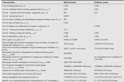
=1573/144=10.9,$/m2year.The energy and cost characteristics of hybrid system are summarized in table 3.
Table 3. The energy and cost characteristics of hybrid and ordinary systems
Characteristics Hybrid system Ordinary system
Cost of heating boiler, Kboil, $ $ 390 $ 650
Cost of ventilation fresh air heating separate boiler, Ksep.boil. , $ $320 $320
Cost of ventilation fresh air heating equipment, KHEX.V, $ $56 $56
Cost of heat pump, KHP, $ $1628 -
Cost of winter condenser for intermediate worming of heating water, Kcond, $ $96 -
Cost of solar air heater, Ksol.heat., $ $ 469 -
Cost of ordinary air conditioners for summer cooling, KAC, $ - $ 3056
Cost of waste gases mixing chamber, Kmix.chamb , $ $ 72 -
Cost of heating-cooling fan coils Kfan-coil, $ $ 268 $ 268
Cost of automation system, Kaut.syst, $ $ 200 $ 200
Total capital cost, ∑Kx1,4, $ 3499x1,4=$ 4899 4550x1,4=$ 6370
Day and night time seasonal consumption of gas in boilers of system for heating and ventilation, Vgas.seas, m3/seas.
1832 m3/seas. 1798+914=2712 m3/seas.
Total cost of seasonal consumption of gas for heating and ventilation, Ugas,
$/seas, 1834,7 x 0,035 = 614 $/seas 2712x0,335=908,5 $/seas
Heat pump’s electricity consumption for heating in heating season,
NHP.wint.seas.,kWh 1868 kWh -
Heat pump electricity consumption for cooling and ventilation in cooling season, Nel.cooling.summ., kWh
1976 kWh (el.consumption of air conditioners)
1976 kWh Heat pump’s annual consumption of electricity, NHP.annual, kWh 1868+1976=3844 kWh -
Cost of annual consumption of electricity by heat pump,
Uel.HP.ann.(Uel.air.cond.ann) $/year
3844kWh x 0,08$/kWh=308 $/year 1976kWh x 0,08$/kWh=158$/year
Annual cost of current repair of the system, Urep. , $/year 4899x0.04=196 $/year 6370x0,04=255 $/year
Total annual operational cost of system ΣU, $/year 614,6+308+196=1119 $/year 908,5+158,3+255=1318 $/year
Annual expenditures for running the system, T, T=4899/25+1119=1315 $/year T=6370/25+1318=251+1318=1573
Specific cost of annual heating and cooling referred to 1m2 of building, T
s, Ts=1315/144= 9.13, $/m2year Ts =1573/144=10.92 $/m2year
Analysis of data of table 3 shows that the specific cost of annual heating and cooling referred to 1m2 of building, T
s,
$/m2 per year for developed hybrid system in 1,79$/m2year or in 20% is less compared to ordinary system. Therefore, wide application of developed hybrid system will provide significant savings of energy and means.
9. Conclusions
1.Research proves possibility of use warm waste gases mixture as low potential source for “gas mixture –air” new type heat pump.
2.The algorithm and mathematical model allow optimizing all characteristics of the hybrid system for variable values of loads of heating boiler β and heat pump ( 1- β) in the
range β=4÷6.
3.Analysis showed rather high energy efficiency and reliability of such kind of heat pump and possibility of its efficient use in developed hybrid system of heating and cooling.
4.Suggested hybrid system of heating and cooling and developed method of its calculation allow designing and implementing energy efficient and cost effective heating and cooling of buildings.
5.Analysis of data, obtained based on method for revealing energy efficiency and cost effectiveness criteria shows that the specific cost of annual heating and cooling referred to 1m2 of building, Ts, $/m2 per year for hybrid
6.Wide application of developed hybrid system will provide significant savings of energy and means.
References
[1] Z. Melikyan, “Heating Cooling of Buildings. Efficiency of conventional and renewable technologies,” LAP Lambert Academic Publishing, Germany, 2012, 345p, ISBN:978-3-8443 -1939-2
[2] Z. Melikyan, “Residential Buildings: Heating Loads,” Encyclopedia of Energy Engineering and Technology, Taylor and Francis: New York, Published online: 2008, pp.1272-1277 [3] Z. Melikyan, V. Nranyan, “Solar Water Heaters: Cylindrical Shell-and-Tube Type,” Encyclopedia of Energy Engineering and Technology, Taylor and Francis: New York, Published online: 2013, 8p.
[4] S. Egnatosyan, “Hybrid System For Heating and Cooling of Houses with “Air to Air” Heat Pump and Heating Boiler,” The
4th International Renewable and Clean Energy Conference, Yerevan, 2009, p.41.
[5] 2013 ASHRAE Handbook—Fundamentals. Chapter: 30-Ther-mophysical properties of refrigerants. Mark S. Owen Editor, 2013, 76p
[6] Z. Melikyan, S. Egnatosyan, “Heating and Cooling Hybrid System with Gas Mixture Sourced Heat Pump and Heating Boiler,” Journal of Energy and Power Engineering, Vol.5, N11, Serial Number 48, USA, 2011, pp.1021-1029
[7] Z. Melikyan, A.Fouda, “Assessment of a modified method for determining the cooling load of residential buildings,” International Journal Elsevier V.35, England, Published online:. 2010, pp.4726-4730.
[8] M. Shogolev, “Fuel, furnace and boilers,” State publishing house on architecture and construction, Moscow, 1953, 546p. (Published in Russian)