Result Analysis of LabVIEW and MatLab in Application
of Image Edge Detection
Ravi Kumar A.V
Asst.Professorr
ECE Department, SJBIT
Bangalore, Karnataka-560060, India
Nataraj K.R, PhD.
Professor
ECE Department, SJBIT
Bangalore, Karnataka-560060, India
ABSTRACT
Edge of an Image is One of the most fundamental and significant futures. Edge detection is always one of the classical studying projects of computer vision and image processing field. It is the first step of image analysis and understanding. The purpose of edge detection is to discover the information about the shapes and the reflectance or transmittance in an image. It is one of the fundamental steps in image processing, image analysis, image pattern recognition, and computer vision, as well as in human vision. The correctness and reliability of its results affect directly the comprehension machine system made for objective world. This paper firstly describes the characteristics of edges, the properties of traditional detectors and the methodology of common edge detection and then analysing the results of MATLAB is commonly used to realize the hybrid programming so as to expand the scientific computing ability of LabVIEW. MATLAB engine must be running in this way and that results in lower perform efficiency and then summarized their recent research progresses and applications. Finally, this paper analyzed their advantages, disadvantages and presents some recommendations for future work
General Terms
ActiveX Server, Math Script, Morphological Processing, Image Edge detection.
Keywords
Developing human-machine interfaces (HMI), Front panel view, integrated development environment (IDE), Image Edge detection, LabVIEW, Morphological Processing, MatLab, Thresholding, Visual programming language
1.
INTRODUCTION
Edge detection refers to the process of identifying and locating sharp discontinuities in an image. The discontinuities are abrupt changes in pixel intensity which characterize boundaries of objects in a scene. Classical methods of edge detection involve convolving the image with an operator (a 2-D filter), which is constructed to be sensitive to large gradients in the image while returning values of zero in uniform regions. There is extremely large number of edge detection operators available; each designed to be sensitive to certain types of edges. Variables involved in the selection of an edge detection operator include:
Edge orientation: The geometry of the operator determines a characteristic direction in which it is most sensitive to edges. Operators can be optimized to look for horizontal, vertical, or diagonal edges.
Noise environment: Edge detection is difficult in noisy images, since both the noise and the edges contain
high-frequency content. Attempts to reduce the noise result in blurred and distorted edges. Operators used on noisy images are typically larger in scope, so they can average enough data to discount localized noisy pixels. This results in less accurate localization of the detected edges.
Edge structure: Not all edges involve a step change in intensity. Effects such as refraction or poor focus can result in objects with boundaries defined by a gradual change in intensity. The operator needs to be chosen to be responsive to such a gradual change in those cases. Newer wavelet-based techniques actually characterize the nature of the transition for each edge in order to distinguish, for example, edges associated with hair from edges associated with a face.
2.
MODELING OF EDGE DETECTION.
[image:1.595.323.547.518.709.2]Edge detection is very basic research field in process of image analysis and measurement, the latter must rely on processing the information it provides and edge extraction directly affects the follow-up to the accuracy and ease of handling. The edge of the image is a set of pixels which spatial image intensity or brightness of the direction of mutation or mutation carrier‘s degree. It is a vector which includes magnitude and direction, in the image it shows the mutation of gray scale. Edge detection is to detect non continuity of a gray image of and to determine their exact position in the image.
According to principles, use gradation differences can be extracted, however, the edge of the image often have arbitrary direction, while the differential operator is directional, so the difference in the same direction with the edge will not be detected, thus hoping to find some of the detection operator to the same Characteristic property, any direction they have the same edge and contour detection. With such properties is sharpening with gradient operator.
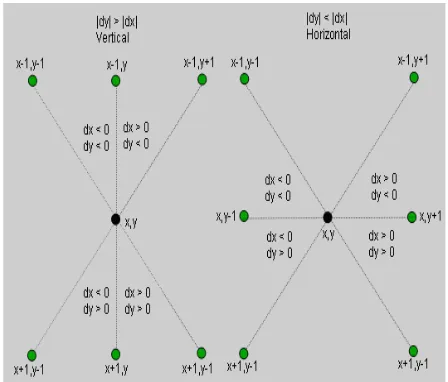
The non-maximal suppression stage identifies pixels that are local maxima in the direction of the gradient using the magnitude and orientation of the pixels. The major orientation of the gradient, either horizontal or vertical, is obtained by comparing the individual components, dx and dy, which are the result of convolving the smoothed image with the derivative of the Gaussian. Since most edges are at an angle, it is possible to obtain further granularity in the orientation of the gradient by comparing the sign bit of the gradient. This allows the neighboring pixels and the orientation of the gradient to be determined within specific quadrants as shown in Fig.1. Once the orientation is determined, the magnitude of the gradient is compared to the interpolated value of the magnitude of the neighboring pixels. The magnitude of the neighboring pixels is calculated using parallel multiplier units. Pixels with gradient intensities less than their neighboring pixels in the gradient direction are automatically suppressed or classified as a non-edge in order to keep the edges thin.
3.
THRESHOLDING
In first-derivative-based edge detection, the gradient image should be thresholded to eliminate false edges produced by noise. With a single threshold t, some false edges may appear if t is too small and some true edges may be missed if t is too large.
[image:2.595.314.559.137.610.2]The final stage involves Thresholding the result from the non-maximal suppression stage to create a binary image using one threshold value. A straightforward approach would include running a first pass over the image to compare all the pixels with the threshold value. Pixels with gradient values above t are marked ‗255‘, classified as an edge. The rest of the pixels are left as zeros, or non-edge. Figure 2 shows an example of this pixel mapping approach. This section of the algorithm alone can contribute to more than 20 operations per pixel. 255=edges 0=non edges
Fig 2: Edge strength classification map
4.
PROPOSED METHOD
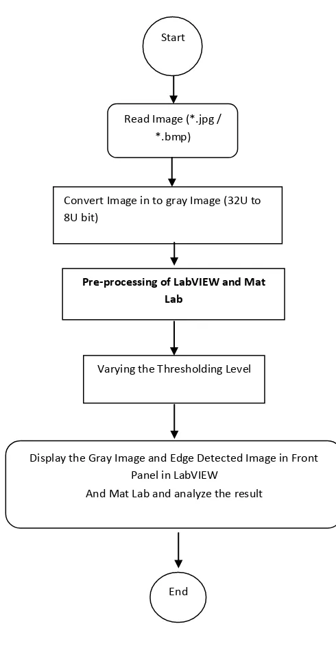
We proposed image edge detection by using [2] LabVIEW and MATLAB and experienced the analysis of both the result of LabVIEW and MATLAB [8] this can be achieved successfully as shown in the fig.3
Fig 3: Methodology to implement edge detection of an image
5.
IMAGE EDGE DETECTION BY
USING LABVIEW.
One of the most fundamental image analysis operations is edge detection. Edges are often vital clues toward the analysis and interpretation of image information, both in biological vision and in computer image analysis. Some sort of edge detection capability is present in the visual systems of a wide variety of Creatures, so it is obviously useful in their abilities to perceive their surroundings.
0 0 0 0 0 0 0
0 0 255 255 255 0 0 0
0 0 255 0 0 255 0 0
0 0 0 255 0 0 0 0
0 0 0 255 255 255 0 0
0 0 255 0 0 0 255 0
0 0 0 255 0 255 0 0
0 0 0 0 0 0 0 0
Read Image (*.jpg / *.bmp)
Start
Convert Image in to gray Image (32U to 8U bit)
Pre-processing of LabVIEW and Mat Lab
Varying the Thresholding Level
Display the Gray Image and Edge Detected Image in Front Panel in LabVIEW
And Mat Lab and analyze the result
[image:2.595.56.275.540.730.2]Fig. 4: Image Conversion Block diagram in LabVIEW
The above block diagram shown in figure 4 is converting RGB image in to gray image by using casting the IMAQ then using pre-processing technique called Discrete Gradient Operators In the continuous-space image, fc (x, y), let x and y represent the horizontal and vertical axes, respectively. Let the discrete-space representation of fc (x, y) be f (n1,n2), with n1 describing the horizontal position and n2 describing the vertical. Let us assume that the positive directions of n1 and n2 are to the right and upward, respectively. For use on discrete-space images, the continuous gradient‘s derivative operators must be approximated in discrete form.
There are many possible derivative-approximation filters for use in gradient estimation.
Let us start with the simplest cases. Two simple approximation schemes for the derivative in one dimension are
First difference: f (n) - f (n-1),
Central difference:1/2 [ f (n + 1) - f (n-1)]
which result in the following 1D Convolutional filters: First difference: h(n)=δ(n) - δ (n - 1) = [1 - 1]
Central difference: h(n) = δ (n + 1) - δ (n - 1) = 1/2 [ 1 0 -1].
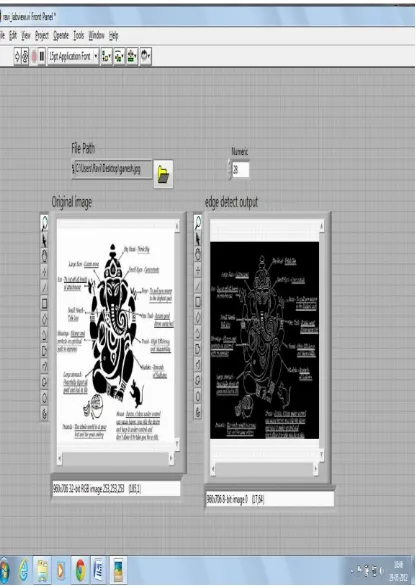
This gradient technique can be implemented by using LabVIEW and MatLab the result is shown in fig.5.
Fig.:5(a) Result of image edge detection by using LabVIEW.
[image:3.595.315.536.87.391.2] [image:3.595.326.534.439.732.2]6.
IMAGE EDGE DETECTION BY
USING MATLAB
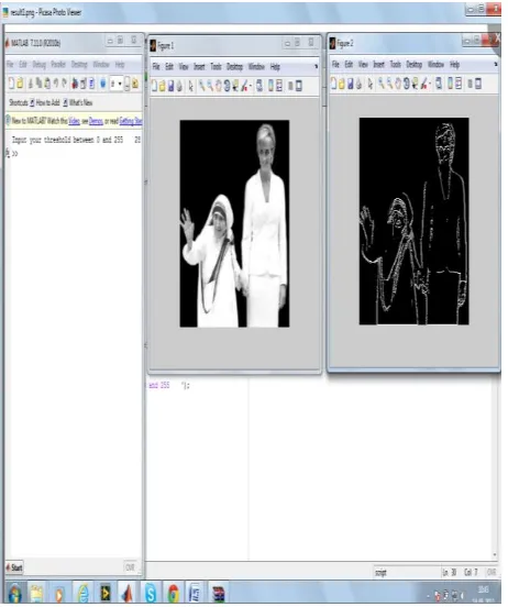
[image:4.595.329.538.80.333.2]Now we implement the image edge detection by using MatLab with same pre-processing technique then we got the result is shown in below.
Fig 6: Flow chart to find Image Edge Detection.
Fig. 7(a): Result to Find Edge detection In MatLab
Fig. 7(b): Result to Find Edge detection In MatLab
7.
RESULT.
We experimented the proposed technique on both LabVIEW and MatLab with biomedical image and natural images. The image, in which the true edges are known, is used to test the edge detection performance by some quantitative measurement is listed below.
LabVIEW is a graphical programming language. Programmers work with two views:
a front-panel view and a schematic diagram view. Since the front panel view is a necessary part of the integrated development environment (IDE), developing human-machine interfaces (HMI) is practically automatic. In fact, it actually is automatic, but the automatically generated HMIs are badly organized. Much of the programming effort goes into ―prettying up‖ the HMI to make it communicate better to humans.
LabVIEW is a visual programming language and Matlab is a text based programming language.\
LabVIEW is a dataflow language and Matlab is a
imperative language.
LabVIEW suits very well for hardware integration, Matlab suits very well for Matrix algebra.
LabVIEW suits very well for interactive applications, Matlab suits very well for data visualization.
LabVIEW suits better for general purpose programming.
LabVIEW code is much easier to debug and as visual programming language LabVIEW code contains much less bugs.
LabVIEW code runs faster than Matlab code, at least in
most occasions.
LabVIEW can run and call MatLab code.
Matlab has a wider OS support, LabVIEW runs on hardware other than normal computers.
START
Read Image
Set the Threshold
Convert RGB Image to Gray Image
Pre-processing the Image to Find the Edges
Display the Edge detected Image
[image:4.595.98.262.138.419.2] [image:4.595.56.287.453.729.2] Planning system architecture is also nearly automatic. The schematic diagram view represents concepts (such as logical operations, mathematical functions, and memory locations), and physical equipment (such as sensors, actuators, and the equipment needed to interface with them) by graphical symbols (objects) with inputs and outputs.
Matlab, on the other hand, has been optimized to make higher mathematics—particularly
Operations with large matrices easy Multiplying two large vectors is as simple as ―U = a * b‖ It‘s no harder because mathematics is a text-based language that translates quite easily to another text-based language. It does not, however, translate as well to graphic
programming.
Some potential benefits of LabVIEW include: Reduced time to discovery – get results faster
Reduced time to prototype – create a functional prototype in less time
Reduced time to market – productize an idea in less time
Smoother technology transfer process – use the same tools as industry to help achieve a smoother and more efficient technology transfer process
Protection of intellectual property – using embedded, field-programmable gate array (FPGA)-based technology
Multidisciplinary development – encourage researchers from different disciplines to contribute to the project using the same development tools
Improved simulations – achieve better/faster prototyping, hardware-in-the-loop (HIL) simulations, and proofs of concept (POCs)
8.
CONCLUSION AND FUTURE WORK.
We have implemented edge detection with different level of threshold by using LabVIEW and MatLab. It is more efficient and easy to implement in LabVIEW compared to MATLAB in real time application. The application can be optimized in multiple ways for detecting more accurate the edges of an image or vision in real time biomedical application. The object as it enters the image, when it is less clear. Another improvement is to combine the results from images to preserve the class consistency of the detected edges.
9.
REFERENCES
[1] M. G. P. Hou, LabVIEW7.1 Programming &Virtual Instruments Designing, Tsinghua University Press,Beijing: 2005.
[2] J. S. F. Yao and D. Q. Xue, Mixed programming between LabVIEW and MATLAB. Software Technology, Vol.24 NO.6 pp.III-112, May.2005. [3] J. F. Pei and C. Y. Wang, Seamless Integration between
LabVIEW and MA TLAB based on COM Technology, Instrumentation users, Vol. 12 No.2 pp.97-98. Nov.2005. [4] J. Y. L. Wang, Z. H. Xiong and H. Ding, Seamless
Integration between LabVIEW and MATLAB ComputerApplication,Vol.26 No.3 pp.696-698 Mar.2006.
[5] Li Li, Dawei Qi, ―Detection of cracks in computer tomography images of logs based on fractal Dimension‖, 2007 IEEE International Conference on Automation and Logistics, IEEE, USA, pp.2259-2264, 2007.
[6] D. F. F. Song, "Image Processing system for Modem Optical Measurement Based on LabVIEW and MATLAB,‖ pp. 46-60, Jan.2007.
[7] X.L. Zhang ―Digital image edge detection with MATLAB‖ J. Journal of jilin institute of chemical technology. Vol.27,no.2, pp.59-61, 2010.
[8] Edge Detection‖, chapter of ―NI Vision Concepts Help‖, online Resource.
[9] T. Kim, Y. Hong, and S. Y. Chang, Joint economic procurement--production-delivery policy for multiple items in a single-manufacturer, multiple-retailer system, Int. J. Production Economics, vol.103, pp. 199-208, 2006.
[10] M. Y. Jaber and S. K. Goyal, Coordinating a three-level supply chain with multiple suppliers, a vendor and multiple buyers, Int. J. Production Economics, vol. 116, pp. 95-103, 2008.
[11] BridgeVIEW and LabVIEW IMAQ Vision for G reference manual, 1996.
[12] G. C. Panayi, ―Implementation of Digital Image Processing Functions Using LabVIEW,‖ M.S. thesis, Dept. of Electrical and Computer Engineering, Univ. of Texas at Austin, May 1999.
[13] The Math works Inc. (1997, June) Building GUIs With
MATLABVersion 5. [Online]
http://www.mathworks.com/access/helpdesk/help/techdo c/creating_guis/creating_guis.shtml