R E S E A R C H
Open Access
Preamble-based channel estimation in
single-relay networks using FBMC/OQAM
Christos Mavrokefalidis
1*, Eleftherios Kofidis
1,2, Athanasios A Rontogiannis
1,3and Sergios Theodoridis
1,4Abstract
Preamble-based channel estimation in filter bank-based multicarrier (FBMC) systems using offset quadrature amplitude modulation (OQAM) has been extensively studied in the last few years, due to the many advantages this modulation scheme can offer over cyclic prefix (CP)-based orthogonal frequency division multiplexing (OFDM) and in view of the interesting challenges posed on the channel estimator by the interference effect inherent in such an FBMC system. In particular, preambles of short duration and of both the block (full) and comb (sparse) types were designed so as to minimize the channel estimation mean squared error (MSE) subject to a given transmit energy. In the light of the important role that relay-based cooperative networks are expected to play in future wireless communication systems, it is of interest to consider FBMC/OQAM, and in particular questions associated to
preamble-based channel estimation, in such a context as well. The goal of this paper is to address these problems and come up with optimal solutions that extend existing results in a single relay-based cooperative network. Both low and medium frequency selective channels are considered. In addition to optimal preamble and estimator design, the equalization/detection task is studied, shedding light to a relay-generated interference effect and proposing a simple way to come over it. The reported simulation results corroborate the analysis and reveal interesting behavior with respect to channel frequency selectivity and signal-to-noise ratio.
Keywords: Channel estimation; Filter bank-based multicarrier; Least squares; Offset quadrature amplitude modulation; Orthogonal frequency division multiplexing; Preamble; Relaying networks
1 Introduction
Future wireless communication systems are expected to adhere to very stringent requirements including high data rates, extended coverage, efficient interference handling and the quality of service anticipated by the end-user. The idea of cooperation is expected to play a key role towards meeting the aforementioned demands. Some examples are the cooperation of multiple base stations and the application of relays in order to mitigate interference and increase the service at the cell edges [1,2]. Cooperation is also expected to be present in infrastructure-less networks like in ad-hoc and sensor networks [3,4].
By utilizing relaying nodes, cooperative communication systems are able to offer capacity and spatial diversity gains with simple single-antenna terminals [3,5]. As in single-link systems, multipath is commonly combatted via
*Correspondence: [email protected]
1Computer Technology Institute and Press - “Diophantus”, Patras University Campus, Patras 26504, Greece
Full list of author information is available at the end of the article
the adoption of cyclic prefix (CP)-based orthogonal fre-quency division multiplexing (OFDM), which is known to be able (under ideal conditions) to transform the chan-nel into a set of parallel flat subchanchan-nels with independent noises. This greatly simplifies the receiver’s tasks such as channel estimation and equalization [6]. However, the use of CP entails a power and spectral efficiency loss (which could be as high as 25%). Moreover, the subcarrier filters, though perfectly localized in time, spread out in the frequency domain, resulting in spectral leakage. This is responsible for the system’s increased sensitivity to fre-quency offsets, Doppler effects and difficulties in user synchronization. Notably, the latter is of great importance in cooperative systems, where synchronization is a very critical issue [7].
Multicarrier schemes based on filter banks (FBMC) have recently shown the potential of overcoming such drawbacks [8,9], thus providing an attractive alternative to OFDM, at the cost of some additional complexity
and delay [10]. When combined with offset quadrature amplitude modulation (OQAM), prototype filters with good localization in both time and frequency are pos-sible, resulting in the so-called FBMC/OQAM modu-lation scheme [11]. The latter avoids the use of CP and has the potential of a maximum spectral efficiency while facilitating the accommodation of multiple asyn-chronous users. Recently, impressive improvements in the throughput of cognitive radio relaying networks employing FBMC/OQAM were demonstrated over their CP-OFDM counterparts [12].
However, FBMC/OQAM suffers from an imaginary intercarrier/intersymbol interference, which complicates receiver tasks that can be straightforward in CP-OFDM. Channel estimation is one of them. A multitude of training designs and associated channel estimation methods are known today for FBMC/OQAM based systems [13]. The design of optimal preambles for the purpose of estimating the channel in FBMC/OQAM single-antenna single-link channels was investigated in [14] (see also [13,15]). Both full (i.e., with pilots at all the subcarriers) and sparse (i.e., with isolated pilot subcarriers surrounded by nulls) preamblesawere considered and their performances were analyzed. FBMC-based techniques were shown to out-perform CP-OFDM particularly when a full preamble is employed.
This paper aims at addressing this problem for the
first time in a cooperative network. To this end, the
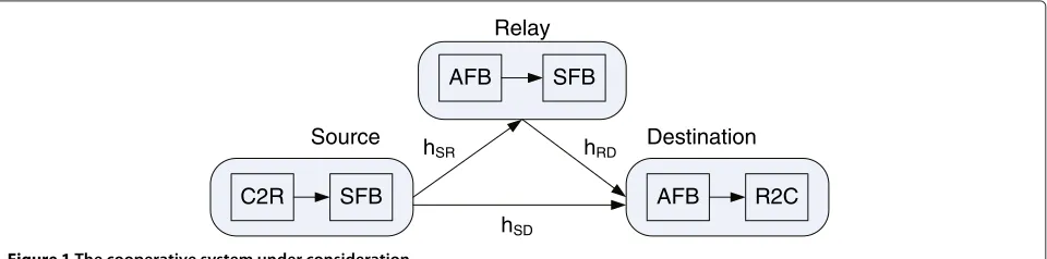
simple yet important system of Figure 1 is considered. Single-antenna transmitters and receivers are assumed. A single one-way half-duplex relay is employed to assist the transmission, following a two-phase amplify-and-forward (AF) protocol. In the first phase, the source transmits to the relay and the destination. In the second phase, the source transmits a new piece of information to the destination and the relay forwards to the desti-nation an amplified version of the signal transmitted by the source during the first phase. This allows the first-phase signal to be received through two different links, thus enhancing the diversity of the system. In a man-ner analogous to a CP-OFDM-based system, filter banks
are employed at the relay terminal to help amplify the received signal per subcarrier. However, the aforemen-tioned imaginary interference along with the real nature of the input symbols versus the complex nature of the filter bank and the wireless channel complicate process-ing at the relay and the destination, and hence, these need to be appropriately adapted to the characteristics of the FBMC modulation employed. The aim is to esti-mate the channels in both paths leading to the destination node.
The problem of the optimal sparse preamble design for a CP-OFDM-based system of this type was recently stud-ied in [16]. Optimality was defined in terms of the mean squared error (MSE) of the least squares (LS) channel estimator subject to a constraint on the total transmitted energy. The same problem is addressed in this paper, but for the more challenging case where FBMC modulation is used. An approach similar to the one of [16] and [14] is fol-lowed. The resulting optimality conditions are analogous to those derived in [16] and dictate that the source should allocate thewholeof its training energy to the first phase, toequispaced and equipowered pilots[17]. Moreover, the relay should also uniformly allocate its energy to the pilot subcarriers to forward the corresponding training signal. The reported simulation results corroborate the analysis and demonstrate a performance similar to that of the CP-OFDM system. An interesting question, that stems from the intrinsic interference effect, comes up when detect-ing the transmitted signal at the destination in the second phase. To answer it, a simple interference cancellation idea is developed and tested.
In sparse preambles, the pilot symbols are guarded by the surrounding nulls and therefore do not interfere with each other. As a result, no pilot symbol energy increase is present at the received signals (as observed in the case of full preambles) and the system turns out to be simi-lar to that based on CP-OFDM in terms of both design conditions and estimation performance. It is thus of inter-est to also invinter-estigate the full preamble case where the situation is quite different and more challenging. In such a scenario, neighboring pilot symbols interfere with each
SFB
AFB SFB
AFB Source
Relay
Destination
hSD
hRD hSR
C2R R2C
other, resulting, effectively, in an energy increase of each pilot symbol at the receiver [18]. This can be advantageous as it attenuates the noise and results in a more accu-rate estimate for the channel [19]. For the FBMC/OQAM single-link case, it was shown in [15] that equal sym-bols maximize this energy increase, offering an estimation performance superior to that of CP-OFDM for practi-cal signal-to-noise ratio (SNR) values. Analogous results about the optimal values of the pilot symbols are shown to hold in the present context [20].
The commonly made assumption of (almost) flat subchannels [13] will be adopted here, for the sake of sim-plicity. Let us recall that this holds true for channels that are not too frequency selective relatively to the size of the filter bank. An additional assumption underlying classical FBMC/OQAM channel estimation techniques and aiming at their simplification is that the coherence bandwidth of the channel is large enough to consider the channel fre-quency response (CFR) invariant over a neighborhood of the subcarrier of interest [18]. Solutions will be also given here when this assumption is relaxed and the differences in the results obtained will be discussed. As a byproduct, the optimal full preamble design for the CP-OFDM-based cooperative system will be derived, through its connection to the FBMC/OQAM system. Simulation results are pre-sented for both mildly and highly frequency selective channels, which corroborate the analysis and demonstrate significant performance gains of the FBMC/OQAM full preamble-based channel estimator over its CP-OFDM counterpart, particularly at practical SNR values.
The rest of the paper is organized as follows. The FBMC/OQAM modulation system and the cooperative communications system employed here are described in Section 2. The problems of (a) sparse and (b) full pream-ble design are addressed in Sections 3 and 4, respectively. Simulation results verifying our theoretical analysis are presented in Section 5 and concluding remarks are made in Section 6.
Notations:In the following, bold lower case and upper case letters denote column vectors and matrices, respec-tively, unless otherwise stated.F denotes the DFT matrix of appropriate order. XT, XH and X−1 denote trans-position, conjugate transposition and inversion of X. Moreover,X−H = X−1H. diag(x) is a diagonal matrix with x on its main diagonal, Tr(X) is the trace of X
and E{.} denotes statistical expectation. Moreover, . denotes the Euclidean norm of a vector, c∗ the
conju-gate of the complex number c and means
element-wise multiplication.0denotes a zero matrix or vector of appropriate size. Finally,x∼CN(μ,)x∼CNμ,σ2
denotes a complex Gaussian random vector (scalar)
with mean μ(μ) and covariance matrix (variance)
σ2.
2 System description
The following two sections will provide all the information about FBMC/OQAM and the cooperative system under consideration that is required for the sequel.
2.1 The FMBC/OQAM system
The output signal of the synthesis filter bank (SFB) is given by [11] complex to real OQAM modulator (C2R block in Figure 1) and
with g being a real symmetric prototype filter impulse response of lengthLg = MK and unit energy.Mis the (even) number of subcarriers,K is the overlapping factor andφ (m,n)=(m+n)(π/2)−mnπ[11]. Finally, the pair
(m,n) corresponds to a frequency-time (FT) point with subcarrier indexmand time indexn.
The signals(l)is transmitted through a frequency selec-tive channel of lengthLh that is modeled by the impulse responseh = [h(0),h(1),. . .,h(Lh−1)]T. Applying the commonly made assumption that the channel is (approxi-mately) frequency flat at each subcarrier [18], the signal at the FT point(p,q), after the receiver’s analysis filter bank (AFB), is given by [14] plex Gaussian channel noisew(l)at the output of thepth subchannel. Assuming thatw(l)is independent and iden-tically distributed asw(l) ∼ CN0,σ2, thenη(p,q) is alsoCN0,σ2. However, nowη(p,q)is correlated among adjacent subcarriers (see, e.g., [15] and [21]).
The summation term in (3) is the associated intrinsic interference coming from the neighboring FT points and weighted by
neighborhoodp,qaround(p,q), i.e. p,q ∈ {(p,q±1),
(p±1,q),(p±1,q±1)}, and (3) can be written as
y(p,q)=H(p)a(p,q)+j
(m,n)∈p,q
H(m)a(m,n)gp,qm,n+η(p,q).
(5)
Finally, (5) can be further simplified if the additional assumption is made that the neighboring CFRs are
assumed equal to each other (H(p) H(p − 1)
H(p+ 1)). This is the case when the channel order is much smaller than the number of subchannels or else for channels with large coherence bandwidth. In this case, (5) can be written as
y(p,q)=H(p)b(p,q)+η(p,q), (6)
where
b(p,q)=a(p,q)+j
(m,n)∈p,q
a(m,n)gp,qm,n (7)
is thevirtually transmitted symbol.
For preamble-based channel estimation, the transmitter sends either a sparse or a full preamble at the beginning of a frame, to assist the receiver in estimating the channel. Preambles consisting of two FBMC symbols will be con-sidered. The first one is a vector of pilot symbolsa(p, 0)
while the second one is a zero vector, i.e. a(p, 1) = 0, for all p, which serves as a guard against interference from the data. For the sake of the analysis, and without loss of generality, the all zeros FBMC symbol that is also commonly sent before the pilots will be omitted here (as in [15]). Its absence, in practice, can be justified, for exam-ple in wireless transmissions that involve inter-frame gaps. It should be also noted here that the two-symbol FBMC preamble is of the same duration as one CP-free OFDM symbol; hence, no extra bandwidth is spent for training. In this case, Equations 6, and 7, withq = 0, correspond to the received signal and the virtually transmitted pilot, respectively, that are associated with channel estimation. It is pointed out, here, that in case no such inter-frame gaps exist, a preceding all-zero symbol is necessary, which results in a preamble of 1.5 CP-free OFDM symbols, i.e., only slightly more than one CP-OFDM symbol. How-ever, the preamble design analysis that follows will not be affected by such a change.
2.2 The cooperative system
The cooperative system under consideration is schemati-cally shown in Figure 1. In analogy with an OFDM-based system, the source S and the destination D utilize an SFB and an AFB, respectively. In order to support per-subcarrier processing, the relay R receives through the AFB, amplifies the subcarrier signals and forwards them to the destination through its SFB.
A two-phase transmission protocol (first proposed in [22]) is adopted. As shown in [23], this protocol offers the optimal diversity/multiplexing trade-off among all the AF half-duplex protocols. The source, the destination, and the relay are single-antenna terminals. For the sake of sim-plicity, it is assumed that S and R are synchronized when transmitting to D during the second phase.
The channel impulse responseshiare modeled asLi×1 complex Gaussian random vectors with independent ele-ments, i.e. hi ∼ CN(0,Ci), where Ci is diagonal and i∈ {SD, SR, RD}. For the sake of the analysis, these chan-nels are assumed (almost) time invariant for the duration of the two phases. Moreover, they are assumed to be short enough to satisfy (6) above.
During the first phase, S transmits the symbolsa1(p,q) to R and D. These are received at the outputs of the corresponding AFBs as
yR(p,q)=HSR(p)b1(p,q)+ηR(p,q), (8) yD1(p,q)=HSD(p)b1(p,q)+ηD1(p,q), (9)
respectively, where b1(p,q) is defined as in (7). As pre-sented in Section 2.1, the noise terms are correlated complex Gaussian with zero mean and variancesσR2,σD2, respectively. The signalyR(p,q)is amplified by the relay as
xR(p,q)=λ(p,q)yR(p,q), (10)
where the per-subcarrier amplification factor λ(p,q) is used to ‘regulate’ the transmitted energy per FT point
(p,q). It is pointed out here that the inputs to R’s SFB are complex valued as opposed to the real a1(p,q) that are sent by S. This is feasible and it is adopted in order to keep the processing as simple as possible and in-line with the AF paradigm.
In the second phase, S and R send the symbolsa2(p,q) andxR(p,q), respectively, to D. These are received as
yD2(p,q)=HSD(p)b2(p,q)+HRD(p)bR(p,q)+ηD2(p,q),
(11)
where ηD2(p,q) is statistically described similarly with
ηD1(p,q), and b2(p,q),bR(p,q) are as in (7) but with a2(p,q)and (complex)xR(p,q)now being the transmitted symbols.
FMBC symbol is set to zero. This way, the interference term in (5) is zeroed.
In the first phase, the training signals received at R and D, are
yD1(p, 0)=HSD(p)a1(p, 0)+ηD1(p, 0), (12)
yR(p, 0)=HSR(p)a1(p, 0)+ηR(p, 0) (13)
respectively, withp ∈ P. The AF operation at the relay during training is here defined as follows. The relay feeds its SFB with the amplified signals ((10) with q = 0) at the pilot subcarriers, whereas it loads the remaining sub-carriers with nulls. Moreover, the next FBMC symbol at the relay (i.e. forq = 1) is transmitted as all zeros. This ‘recovers’ the original preamble structure as sent by the source, yet with complex-valued inputs at the pilot sub-carriers. Thus, the received signal at the destination in the second phase and at the pilot subcarriers can be expressed as
The latter has zero mean and variance
σw2 therefore independent ofp(for uncorrelated channels as assumed here).
It will be convenient to write Equations 12 and 14 in the following compact form:
Moreover,ηD1 andw2are defined similarly to (19). Addi-tionally, in (18), theL×LmatrixFL×L results from the Mth-order DFT matrixF by keeping its first Lcolumns and itsLrows indexed byP. Here, it is assumed for sim-plicity and without loss of generality thatLSD = LR = L and thatM/Lis an integer. If necessary, these conditions can be satisfied by appending an appropriate number of
zeros to the impulse responses. With a straightforward matching of terms, (18) can be written as
y=XF¯Lh+w=Bh+w, (22)
where the matrix
B=XF¯L (23)
is square of order 2Land obviously nonsingular. The noise
term w is a zero mean random vector with covariance
matrix (22), the LS estimate ofh and its covariance matrix are expressed as [24]
ˆ
h=B−1y, (25)
Chˆ =B−1CwB−H (26)
The per-subcarrier amplification factor during the preamble period will be set to (see also [16])
λ(p, 0)=
ER(p, 0)
θSR2a21(p, 0)+σR2, (27)
with p ∈ P, where ER(p, 0) is the energy assigned by the relay when forwarding the pth pilot signal and θSR2
is defined in a manner analogous to θRD2 (and is hence independent ofp).
In the following, the optimal preamble design for the aforementioned setup will be provided. The aim is to appropriately choose the pilot symbolsak(p, 0)and their
positions p ∈ P, so that the normalized MSE =
1 2LTr
Chˆ
is minimized subject to a constraint on the total energy spent for transmitting (and forwarding) the preambles in the two phases. One can show that the MSE here only depends on the energies of the pilot sym-bols and not on their specific values. This fact will soon become apparent.
3.1 Problem formulation
and the relay, respectively. The optimal placement P of the pilot symbols is also to be optimized.
A simplification of the above cost function will be quite helpful in the sequel. Using the formula forChˆ from (26) and the definitions from (22), one can write
Tr
where the well-known property of the trace operator for matrix products has been employed. Next, the application of the matrix inversion lemma in the 2× 2 block (with diagonal blocks) matrixXHCwX
whereUis a diagonal matrix with itslth diagonal element, l=1, 2,. . .,L, given by
Finally, by definingvl =
FL×LFHL×L −1
l,l,l = 1, 2,. . ., L, the minimization can be based on the following equiv-alent expression for the cost function
MSE= 1
3.2 Optimal energy allocation between phases
First, the optimal spliting of the total energy at the source in the two phases is investigated. Writingαk(l)as a frac-minimization is performed for 0 ≤ E1 ≤ ES. Because df(E1) /dE1 is negative, this function is monotonically decreasing and its minimum value is forE1=ES, implying thatE2=0 andα2=0.
3.3 Optimal pilot placement
After incorporating the results of the previous subsection, the minimization problem is transformed into
min
The optimization with respect toP can benefit from the following lower bound [25]
Equality holds in (34) when the positioning setP is con-structed by equispaced pilot positions (e.g.pl= ML(l−1), forl = 1, 2,. . .,L). This is true for any allocation of the pilot energies.
3.4 Optimal allocation of energy to pilots
By considering equispaced pilot positions, the minimiza-tion problem reduces to
This can be readily solved using Lagrange multipliers. The conclusion is that the energy allocation should be uniform across the pilot symbols. This leads toα1(l) = ES/Land e(l)=ER/Lforl=1, 2,. . .,L.
From the previous analysis, the following remarks can be made:
1. The above results are in line with those derived in [16] for the CP-OFDM-based system. This is not unexpected in view of the fact that the type of the preamble considered (i.e., sparse) removes intrinsic interference and brings the problem quite closely to that for CP-OFDM. Analogous results, for single-link (not relaying) FBMC/OQAM systems, were also shown in [14].
2. It is interesting to observe that the estimator in (25) takes a simple form when the optimal preamble is used. Indeed, Equation 25, assuming also for simplicity equal symbols, becomes
estimation of the two branches is actually decoupled. 3. In order to better appreciate the needs of D for
channel information, a simple, per-subcarrier, single-tap zero forcing (ZF) equalizer for recovering the transmitted data at the destination node is considered. It turns out that an additional
D needs to first estimate the virtual symbolsbk(p,q) and from them detect the corresponding input symbolsak(p,q),k=1, 2. The detected symbols are then OQAM-demodulated (real to complex (R2C) block in Figure 1). Data recovery is performed at the end of the second phase. To see how this can be done, rewrite first Equations 9 and 11:
yD1(p,q)=HSD(p)b1(p,q)+ηD1(p,q), (37)
yD2(p,q)=λ(p,q)HR(p)b1(p,q)+HSD(p)b2(p,q)
+I(p,q)+w2(p,q),
(38)
where
I(p,q)=jHRD(p)
(m,n)∈p,q
λ(m,n)HSR(m)b1(m,n)gp,qm,n
(39)
and
w2(p,q)=HRD(p) ⎡ ⎣j
(m,n)∈p,q
λ(m,n)ηR(m,n)gp,qm,n
+λ(p,q)ηR(p,q)
⎤
⎦+ηD2(p,q)
(40)
is the composite noise at D in the second phase. As it will be verified in the simulation results,I(p,q)
needs to be canceled out in (38) for a better detection performance. However, Equation 39 implies that D would also need an estimate of the S-R and R-D channels in order to cope with this interference term. This is more than commonly required from the destination node in the channel estimation literature for such systems (cf. e.g., [16]), namely estimates of the overall channels in the two paths from S to D only. One can see, however, thatI(p,q)can be approximated by using the assumption (underlying (11)) thatHSR(m)≈HSR(p), for
(m,n)∈p,q. This way,HSR(p)is factored out of the summation in (39) and the known channelHR(p) appears. Moreover,b1(m,n)can be estimated from (9) based on theHSDestimate, while the quantitiesgp,qm,narea priori known from the adopted prototype filterg [13]. OnceI(p,q)has been canceled out, and an estimate ofb1(p,q)is available, a ZF equalizer can be applied in (38) too, to estimate b2(p,q).
4 Channel estimation using full preambles
In the following, the full preamble design will be presented first under the commonly adopted assumption of equal neighboring subcarrier CFRs (e.g. [18]) that is valid for channels of large coherence bandwidth. As already men-tioned, the energy increase at the pseudo-pilots that are generated at the receiver leads to a better estimation per-formance than CP-OFDM. Then, the more realistic case where no such assumption is made for the neighboring subcarrier CFRs will be addressed. Simulation results will show that this only brings improvement at the weak noise regime, where the model inaccuracy becomes apparent. At low SNRs however, the strong noise hides the incor-rectness of the assumption, while the (artificial) pseudo-pilots are of sufficiently large magnitude to successfully cope with this noise.
4.1 Channels of large coherence bandwidth
As in the case of the sparse preamble, the source trans-mits two known FBMC symbols. The first one is a vector of training symbolsa(p, 0)(which is full) while the second one is a zero vector, i.e.a(p, 1) = 0, for all p, which as previously serves as a guard against interference from the data. Due to the good frequency localization of the proto-type filter employed in the filter bank, and in view of this preamble structure, the interference to the pilot at sub-carrierponly comes from its adjacent subcarriers,p±1. In order to facilitate the presentation that follows, we will make a slight abuse to the OQAM definition, by incorpo-rating the phase factorsejφ(p,0) in the training symbols, resulting inx(p, 0) = a(p, 0)ejφ(p,0)(this is adopted as in [15] in order to assist the forthcoming analysis and espe-cially the minimization problem (54)). Of course,gp,0also needs to be accordingly modified, namely, in (2), the factor ejφ(m,n)is omitted for(m,n)=(p, 0). This results in
l
gm+1,0(l)gm,0∗ (l)=
l
gm−1,0(l)gm,0∗ (l)=β (41)
meaning that the interference corresponding to jgp,0m,0 in (7) form = p±1 is purely real with β > 0 defined in [13]. Some indicative values for the prototype filter used in the simulations with overlapping factor K = 3 are
β = 0.2497 andβ = 0.25 forM = 64 andM = 256,
respectively. Hence, the corresponding virtual pilot sym-bolb(p, 0)is given by
b(p, 0)=x(p, 0)+x(p−1, 0)β+x(p+1, 0)β (42)
In the following, the time index will be dropped for convenience. The received signals in the first phase are
yR(p)=HSR(p)b1(p)+ηR(p), (43) yD1(p)=HSD(p)b1(p)+ηD1(p), (44)
for R and D, whereb1(p)’s are defined according to (42). During the second phase, the source and the relay send a new two-symbol full preamble of the above structure, using this timex2(p) andxR(p)(in the first FBMC sym-bol). The relay employs the following amplification factors
λ(p)=
which set the mean energy per subcarrierpat the input of the relay SFB toe(p). The received signal at D, during the second phase, can be written as
yD2(p)=HSD(p)b2(p)+HR(p)b3(p)+w2(p), (46)
where theb2(p)’s are defined according to (42) and
b3(p)=λ(p)b1(p)+λ(p−1)b1(p−1)β
+λ(p+1)b1(p+1)β,
(47)
for allp. Moreover,
w2(p)=HRD(p)λ(p)ηR(p)+HRD(p)λ(p−1)ηR(p−1)β
+HRD(p)λ(p+1)ηR(p+1)β+ηD2(p)
(48)
is a zero mean random variable with variance equal to
σw2
whereθRD2 is defined as in the sparse preamble case while our knowledge of the correlation of adjacent noise com-ponents (equal toσR2β[15]) has also been used.
Putting Equations 44 and 46 together results in
where it is natural to assume the matrixBto be nonsingu-lar. The noise termwis zero mean with covarianceCw = diagCηD1,Cw2
. The diagonal blocks ofCware not diag-onal matrices. However, as it will be observed later on, we are only interested in their diagonal elements, which
areCηD1
The LS estimate ofHand the associated error covariance matrix are given by [24]
ˆ
H =B−1y, (52)
CHˆ =B−1CwB−H (53)
4.1.1 Preamble design
The training design consists of (a) the source training energy allocation between the two transmission phases, (b) determination of the source training symbolsxk(p) =
ak(p)ejφk(p),k=1, 2 and (c) distribution to the subcarrier signals the transmit energy available at the relay in the sec-ond phase. In a manner analogous to the sparse preamble case, the preamble optimization criterion will be to min-imize the normalized MSE = 2M1 TrCHˆsubject tosum energy constraints at the source and the relay, namely
minx1,x2,e,E1,E2 ande(p)’s, respectively,Ek is the source energy allocated to training in phasekandER,ESare given energy budgets. The two energy constraints, defined at the output of the source and the relay SFBs, follow the analysis that was pre-sented in the extended version of [14]. In (57), the relay energy is constrained in a mean sense.
It will be convenient to re-write the cost function above in an alternative form. Specifically, by applying the matrix inversion lemma to the 2×2 block matrixB−1with diago-nal blocks, it can be shown that the trace in (54) is applied on a sum of diagonal matrices. The normalized MSE can then be written as MSE= 2M1 Mp=−01vp, where
source or the relay. Due to the interference effect not being negligible in this scenario of a full preamble, these are in general different from the energies at the SFB input (see also [14,15]). Second, due to the orthogonality of the SFBs, the energies at the inputs of the SFBs can be con-strained asMp=−01%%x1(p)%%2 ≤ E1 andMp=−01%%x2(p)%%2 ≤ E2 for the source and Mp=−01e(p) ≤ ER for the relay (see also [14,15]). Furthermore, it can be shown [15] that M−1
p=0 %%bk(p)%%2≤(1+2β)2 M−1
p=0 %%xk(p)%%2,k=1, 2.
4.1.2 Optimal energy allocation between the phases
The optimal allocation of the total energy ES (equiva-lentlyES) at the source between the two phases dictates that E1 = ES, implying that E2 = 0 and x2 = 0. The proof of these results follows the same steps as in the sparse preamble case and, hence, it is not repeated here.
4.1.3 Solution for x1(p)s and e(p)’s
The optimization problem is now written as follows
minx1,e
The cost function in (60) has a complicated form with respect to the unknown parameters. This is due to the fact that the amplification factorsλ(m), form=p−1,p,p+1, which appear at both the numerator and the denomi-nator of the second term in (60), are in turn nonlinear functions of the b1’s ande’s. It thus seems that an ana-lytical, closed-form expression for the optimal parameters is difficult to be found. However, targeting such a solu-tion, we first derive a lower bound, which will suggest a simplification allowing us to come up with an analytical solution.
Indeed, by using the triangle inequality at the denomi-nator of the second term in (60), we can write
%%b3(p)%%2≤%%λ(p)b1(p)%%+%%λ(p−1)b1(p−1)β%%
+%%λ(p+1)b1(p+1)β%%2≡L1(p),
(63)
where the equality holds iff theb1’s have the same phase. Applying the Cauchy-Schwartz inequality in its numerator leads to function in (60) can then be lower bounded as
MSE≥ 1
where the equality holds under the aforementioned con-ditions.
The above suggests that letting theλ’s at a subcarrierp and its immediate neighbors be equal is a plausible choice. This is a first approach to be analyzed below. In a second approach to simplifying the problem, the relay is assumed to operate at a high SNR regime, i.e.,σR2≈0. and resorting to the arithmetic-harmonic mean (AHM) inequality for the first and second terms, (66) is written as
MSE≥ M
(61), (62) hold with equality if ES(1 + 2β) = ES and
4.1.5 The relay operates at high SNR
With σR2 ≈ 0, we have L2(p) ≈ σD2 and L1(p) = θSR−2
where the first inequality is due to the AHM inequal-ity and the second to the above constraints. The bound holds with equality for %%b1(p)%%2 = ES(1+2β) mizes (60). This is the desired solution for (60) if the constraints (61), (62) hold with equality, which is true if, additionally, ES(1 +2β) = ES and ER(1+2β) = ER, respectively.
Remark 1: In both of the cases analyzed above, the
choice of all equal x1(p) is shown to be a solution. It is interesting to recall that this is in line with the opti-mal preamble design in single-link FBMC/OQAM sys-tems [13], where it was shown to maximize the virtual pilot energies in (42). Moreover, this choice of the pilot symbols, in conjuction with the uniform energy alloca-tion at the relay, also leads to all equalλ’s, something that was only assumed in the first approach. Note also that the matrixBin (51) becomes diagonal (and indeed nonsin-gular) and has a form similar to the one for the sparse case.
Remark 2:As indicated in [18], the condition of equal pilots can lead to a high peak-to-average power ratio (PAPR) for the modulated preamble signal. This is a well-known problem, already discussed in earlier works on FBMC/OQAM (see, e.g., [13]) and CP-OFDM [26].
4.1.6 The CP-OFDM case
It is of interest to note that the corresponding problem for CP-OFDM can be formulated as previously by simply settingβ = 0. Hence, a solution to this problem can be easily derived here as a by-product.
Denoting the energies%%xk(p)%%2byαk(p)fork=1, 2, the associated cost function and constraints can be written as
MSE= 1 case, only the pilot energies are of interest in the pream-ble design, not their values. This propream-blem can be optimally solved and the result is that S uniformly allocates all its energy to the first phase and R forwards the pilot signals by assigning uniform energy per subcarrier. A similar problem was studied in [27], although there the relay plays no significant role in the design as its amplification is not performed per subcarrier as it is here.
4.2 Channels of low coherence bandwidth
Here, we check what happens in more realistic scenarios where the channel is more frequency selective than the model in (5) requires. Focusing onx(p, 0)as in the previ-ous section and dropping the time index, Equation 5 can be written as
where B is a circulant matrix with first row equal to [ 1 β 0 · · · 0 β ], X = diag(x(0),x(1),. . .,x(M−1)),
H =[ H(0) H(1) · · · H(M−1) ]Tand
η=η(0) η(1) · · · η(M−1)T (72)
withη∼CN0,σ2B.
In more detail, during the first phase and focusing on the first (non-zero) preamble FBMC symbol, S transmits the symbolsx1(p)to R and D. These are received as
yR=BX1HSR+ηR, (73)
yD1 =BX1HSD+ηD1, (74)
respectively. The noise terms are described as ηR ∼
Let the received signal at R be first multiplied by
B−1. It is pointed out here that this multiplication can be efficiently performed by exploiting the circu-lant nature of B−1, i.e. by utilizing FFT/IFFT oper-ations and the (known) eigenvalues of the matrix.
Finally, R amplifies the outcome by the factors =
diag(λ(0),λ(1),. . .,λ(M−1)). Thus, energy per subcarrier that is allocated by R.
During the second phase and focusing again on the first (non-zero) preamble FBMC symbol, S transmits the sym-bols x2(p) to D and R transmits the symbolsxR(p), i.e. the elements ofxR(it is reminded that these symbols are followed by an all-zeros one). The received signal is
yD2=BX2HSD+BXRHRD+ηD2
The destination uses (74), (77) in order to estimate the two CFRs H = HTSD HTR T. After multiplying each equation withB−1, i.e. yDi = B−1yDi fori = 1, 2, the following input-output relation can be written as
th element has variance equal toσ2
w2(p)=λ 2(p)θ2
RDσR2+
σD2. It is noted thatσD2=σD2B−1iisimilarly withσR2.
In compact form and with direct matching of terms, (78) can be written as
y=XH+w (79)
The noise termw is zero mean with covariance Cw =
diagCηD1,Cw2
. The diagonal blocks ofCware not diag-onal matrices. However, as it will be observed later on, we are only interested in their diagonal elements, which are Finally, the LS estimate of H and the associated error covariance matrix are given by
ˆ
H=X−1y, (80)
CHˆ =X−1CwX−H (81)
4.2.1 Preamble design
Similarly to the previous section, the training design prob-lem is defined as follows:
min
The cost function can also be simplified following the procedure of the previous sections. The normalized MSE can then be written as MSE= 2M1 Mp=−01vp, where
The simplified cost function is similar to the one of CP-OFDM, i.e. (68). Using the corresponding energy con-straints at the SFB inputs (i.e. Mp=−01e1(p) ≤ E1 and M−1
here is as previously described. In more detail, the source should set E1 = ES, E2 = 0, x1(p) = √ES/Mejφ1(p) andx2(p) = 0. Moreover, the relay should seteR(p) =
√
ER/M. Finally, this solution is also the solution to the original problem, i.e. with the constraints at the outputs of the SFBs, when those constraints are tight. This is achieved when additionally the phases of the pilot symbols are equal to each other, namely,x1(p)=√ES/Mejφ.
5 Simulation results
In the following, the energy budgets for training at S and R are chosen equal to the number of pilot symbols that are used in each case so as to have mean energy per pilot symbol equal to 1. QPSK data are transmitted (with a unit energy per bit). Moreover, the noise signals at the desti-nation and the relay are assumed of equal power. Filter banks, designed as in [28], are employed, with overlap-ping factorK=3. The performance of the corresponding CP-OFDM system is included, for the sake of the compar-ison, where a CP of minimum length (equal to the channel order) was assumed. Results are shown for two channel models, with all the channels undergoing Rayleigh block fading. In the first case, they are generated with an expo-nential profile (of unit decay) and lengthsLSD=4,LSR= 3, andLRD =2. The ITU Veh-A profile is assumed in the second case, with a sampling rate equal to 0.9 GHz. The resulting channels have the same lengths LSD = LSR = LRD = 11. In this second case, the SRD channel is much longer than the direct one, namelyLR=21. Thus, to con-form with the assumptions made earlier, one may assume
that the SD impulse response is appended with 10 zeros here.
5.1 The sparse preamble case
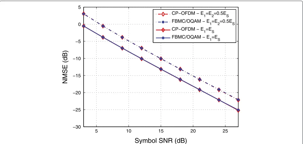
M=256 subcarriers are used. First, channels of low frequency selectivity will be considered using the exponential channel profile as described above. This channel approaches the requirement of equal neigh-boring CFRs. In Figure 2, the normalized MSE (NMSE)
E
---h−hˆ---2/h2
is plotted versus SNR, for both
optimal (E1=ES) and suboptimal (E1=E2=0.5ES) source energy allocations between the two phases. All other training conditions hold as dictated by the optimal training design. As expected, the performance is sig-nificantly better when the optimal design is employed.
Moreover, the two multicarrier systems perform
similarly.
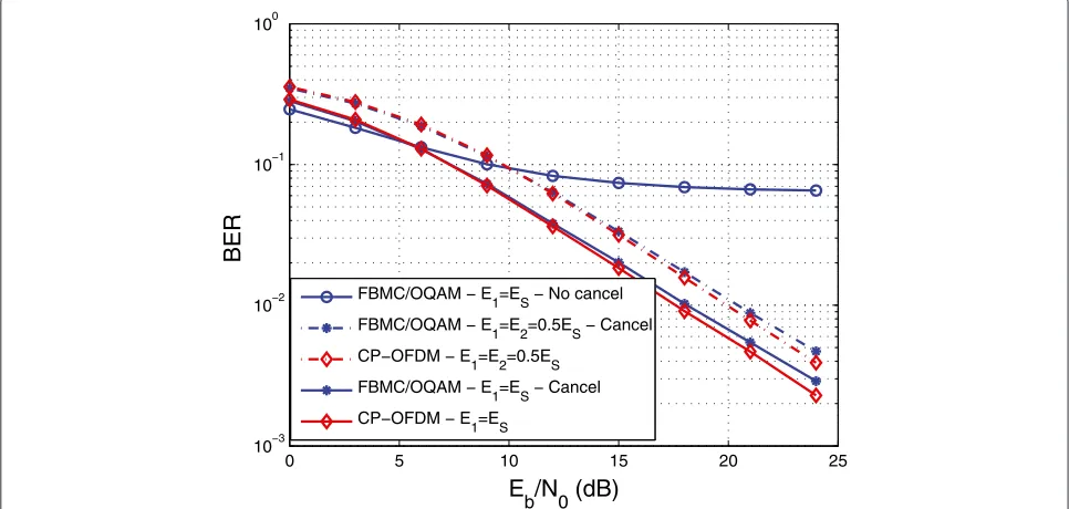
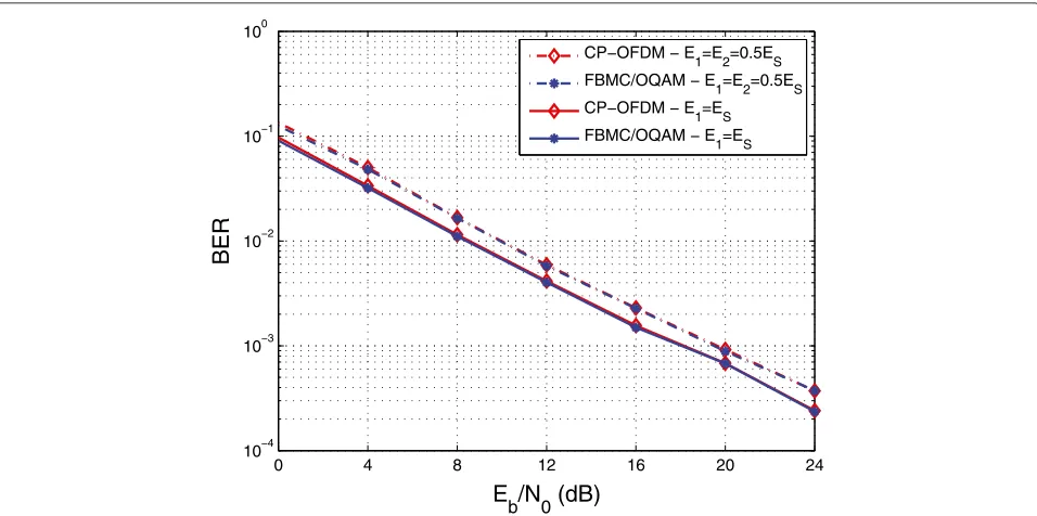
In Figures 3 and 4, the (uncoded) bit error rate (BER) performances at the destination detector with QPSK input are shown for phases 1 and 2, respectively. It is pointed out here that these results are given in order to observe the impact of the additional interfering term that was identified in (38) and not to propose a new detection scheme for the adopted transmission protocol. This is due to the fact that no diversity combining techniques were utilized to increase the detection performance, meaning that the signals received at the destination, in the two phases, are actually processed separately. The SNR loss incurred by the CP redundancy in CP-OFDM was taken
5 10 15 20 25
−30 −25 −20 −15 −10 −5 0 5
Symbol SNR (dB)
NMSE (dB)
CP−OFDM − E
1=E2=0.5ES FBMC/OQAM − E
1=E2=0.5ES CP−OFDM − E
1=ES FBMC/OQAM − E
1=ES
0 5 10 15 20 10−4
10−3 10−2 10−1 100
E
b
/N
0(dB)
BER
CP−OFDM − E1=E2=0.5ES
FBMC/OQAM − E1=E2=0.5ES
CP−OFDM − E 1=ES FBMC/OQAM − E
1=ES
Figure 3The sparse preamble case for the exponential channel profile forM=256,K=3, andL=4.BER for the (QPSK) data transmitted in the first phase. Optimal and suboptimal energy allocation schemes are compared.
into account when calculating the corresponding BER. In the FBMC/OQAM-based relay, the amplification factors were chosen so as to have unit energy per information bit at the channel inputs of the S-R-D chain. One can observe a significant performance gain (of about 2 to 3 dB) over the suboptimal source energy allocation. Moreover, and not
unexpectedly, the two multicarrier systems perform simi-larly in the detection of the first phase data (cf. Figure 3). In Figure 4, however, the destructive effect of the identi-fied interference term (see Equation 39) and the impor-tance of its (approximate) cancellation are demonstrated. Observe the severe error floor in the optimal case without
0 5 10 15 20 25
10−3 10−2 10−1 100
E
b/N0 (dB)
BER
FBMC/OQAM − E1=ES − No cancel
FBMC/OQAM − E1=E2=0.5ES − Cancel
CP−OFDM − E1=E2=0.5ES
FBMC/OQAM − E1=ES − Cancel
CP−OFDM − E1=ES
5 10 15 20 25 −30
−25 −20 −15 −10 −5 0 5
Symbol SNR (dB)
NMSE (dB)
CP−OFDM − E1=E2=0.5ES
FBMC/OQAM − E1=E2=0.5ES
CP−OFDM − E 1=ES FBMC/OQAM − E
1=ES
Figure 5The sparse preamble case for the Veh-A channel profile forM=256,K=3, andL=32.NMSE performance of the optimal and suboptimal energy allocation between the two phases.
cancellation. On the other hand, no cancellation seems to be the best choice at low SNR values, because of the errors incurred then at the interference approximation due to channel estimator errors and a1 decision error prop-agation. FBMC/OQAM performs slightly worse at the
weaker noise region. This is attributed to the non-perfect interference cancellation (which becomes more apparent in this noise region) and the composite noise termw2(p, 0) in (14) at the FBMC destination receiver because of the interference effect. One should add to this the effect of the
0 4 8 12 16 20 24
10−4 10−3 10−2 10−1 100
E
b/N0 (dB)
BER
CP−OFDM − E1=E2=0.5ES
FBMC/OQAM − E1=E2=0.5ES
CP−OFDM − E1=ES
FBMC/OQAM − E1=ES
0 4 8 12 16 20 24 10−4
10−3 10−2 10−1 100
E
b/N0 (dB)
BER
FBMC/OQAM − E
1=ES − No cancel FBMC/OQAM − E
1=E2=0.5ES − Cancel CP−OFDM − E1=E2=0.5ES
FBMC/OQAM − E1=ES − Cancel
CP−OFDM − E1=ES
Figure 7The sparse preamble case for the Veh-A channel profile forM=256,K=3, andL=32.BER for the (QPSK) data transmitted in the second phase. Optimal and suboptimal energy allocation schemes are compared.
residual interference caused by the fact that the subchan-nels in (12) and (14) are only approximately frequency flat. The same experiment was performed for the Veh-A channel profile and thus, in this case,L=32. Figures 5, 6, and 7 shows the NMSE and the BER curves for the first and the second phase transmissions. The conclusions
drawn for Figures 2 to 4 are still valid here. However, as observed in Figure 7, FMBC/OQAM performance starts to floor at lower SNR values than previously, because the overall associated channel (S-R-D) is now longer and hence the assumption that leads to (6) is less well approximated.
5 10 15 20 25 30
−35 −30 −25 −20 −15 −10 −5 0 5 10
Symbol SNR (dB)
NMSE (dB)
CP−OFDM − scenario 3 CP−OFDM − scenario 2 CP−OFDM − scenario 1 FBMC/OQAM − scenario 3 FBMC/OQAM − scenario 2 FBMC/OQAM − scenario 1
5 10 15 20 25 30 −40
−35 −30 −25 −20 −15 −10 −5 0 5 10
Symbol SNR (dB)
NMSE (dB)
CP−OFDM − scenario 3 CP−OFDM − scenario 2 CP−OFDM − scenario 1 FBMC/OQAM − scenario 3 FBMC/OQAM − scenario 2 FBMC/OQAM − scenario 1
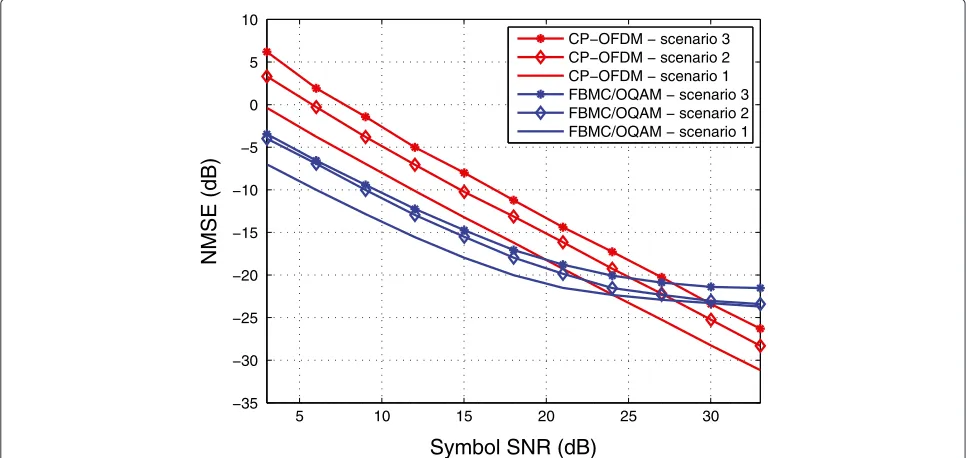
Figure 9The full preamble case assuming invariant neighboring CFRs (channels of large coherence bandwidth).Estimation performance for more frequency-selective channels (Veh-A channel profile).M=256,K=3.
5.2 The full preamble case
In this section, simulation results are reported for the full preamble structure. Veh-A channels were assumed for M=64 andM=256 subcarriers.
5.2.1 Assuming equal neighboring CFRs
Three scenarios were examined. In the first one, the derived optimal training conditions were respected. In the
second and third scenarios,E1 = E2. The third scenario also permits the relay to depart from the uniform energy allocation and employ randomly chosenλ’s. The results are depicted in Figures 8 and 9 forM=64 andM=256, respectively. The normalized MSE performance is plotted versus SNR. In Figure 8, as expected, the FBMC/OQAM performance is considerably better at practical SNRs. One can also see that the violation of the training conditions
5 10 15 20 25 30
−35 −30 −25 −20 −15 −10 −5 0
Symbol SNR (dB)
NMSE (dB)
CP−OFDM
FBMC/OQAM − Variant CFRs FBMC/OQAM − Invariant CFRs
5 10 15 20 25 30 −40
−35 −30 −25 −20 −15 −10 −5 0
Symbol SNR (dB)
MSE (dB)
CP−OFDM
FBMC/OQAM − Variant CFRs FBMC/OQAM − Invariant CFRs
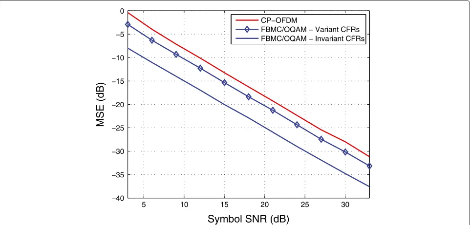
Figure 11The full preamble case but with no assumption on the neighboring subchannel responses.Estimation performance for less frequency-selective channels (Veh-A channel profile).M=256,K=3.
deteriorates the performance for both multicarrier sys-tems. Moreover, at weak noise regimes, the inaccuracies of the assumed input-output model, which relies on the assumption of relatively low channel frequency selectiv-ity, become more apparent, resulting in the well-known error floors in the FMBC/OQAM performance [13]. In Figure 9, similar conclusions can be drawn. However, in this case, the error floors are not present anymore because increasing the number of subcarriers leads to lower channel frequency selectivity and hence higher model accuracy.
5.2.2 Dropping the previous assumption
Here, the FBMC estimation performance is examined when the assumption of invariant CFRs is dropped. The simulation results are plotted in Figures 10 and 11 for M=64 andM=256, respectively, namely for conditions of high and low relative frequency selectivity. As one can observe, the estimation performances of FBMC are bet-ter than the CP-OFDM one for practical values of SNR. Moreover, in both figures, and at low SNR values, the use of the assumption of locally invariant CFR provides bet-ter estimates. This entails the use of ‘pseudo-pilots’ whose magnifying effect on the pilots’ magnitude attenuates the channel estimation error, something which is more impor-tant when the noise power is high. However, in the weak noise regime, the model inaccuracies become apparent and the relaxation of the above assumption leads to a better performance (a lower error floor - see Figure 10) because it describes the system more accurately. Relying
on the assumption of a constant CFR can be advantageous at higher SNRs too, provided that the channel meets this requirement closely enough (see Figure 11).
6 Conclusions
In this paper and for the first time in such systems, preamble-based channel estimation was studied in an FBMC/OQAM-based cooperative network of a source-destination pair that is supported by an AF relay. Both sparse and full optimal preamble designs were addressed. In the former case, the solution was given for both the optimal power allocation and pilot placement prob-lems. In the latter case, we considered the design of the channel estimator and the associated preamble for both channels of large and smaller coherence band-width. The corresponding problem for CP-OFDM was also addressed, viewing CP-OFDM as a special case of the FBMC/OQAM-based system. The effects of sub-channel frequency selectivity on the attained estimation and detection performance were evaluated via simulation results.
Future research in this context will be directed towards the more realistic scenarios of frequency-selective sub-channels and lack of synchronism among nodes in the network.
Endnotes
aSometimes referred to in the OFDM literature asblock
bIt is tacitly assumed here that the composite channel is
short enough to meet the assumptions stated in Section 2.1 that validate (6).
Competing interests
The authors declare that they have no competing interests.
Acknowledgements
This work was supported by an FP7 grant, project EMPhAtiC (http://www.ict-emphatic.eu/).
Author details
1Computer Technology Institute and Press - “Diophantus”, Patras University
Campus, Patras 26504, Greece.2Department of Statistics and Insurance
Science, University of Piraeus, Piraeus 18534, Greece.3IAASARS, National
Observatory of Athens, Penteli 15236, Greece.4Department of Informatics and
Telecommunications, University of Athens, Athens 15784, Greece.
Received: 12 December 2013 Accepted: 21 April 2014 Published: 10 May 2014
References
1. D Gesbert, S Hanly, H Huang, S Shamai, O Simeone, W Yu, Multi-cell MIMO cooperative networks: A new look at interference. IEEE J. Selected Areas Commun.28(9), 1380–1408 (2010)
2. SW Peters, AY Panah, KT Truong, RW Jr. Heath, Relay architectures for 3GPP LTE-Advanced. EURASIP J. Wireless Commun. Netw. (2009). doi:10.1155/2009/618787
3. B Zafar, S Gherekhloo, M Haardt, Analysis of multihop relaying networks: Communication between range-limited and cooperative nodes. IEEE Vehicular Technol. Mag.7(3), 40–47 (2012)
4. YM Hong, WJ Huang, FH Chiu, CC Jay Kuo, Cooperative communications in resource-constrained wireless networks. IEEE Signal Process. Mag. 24(3), 47–57 (2007)
5. S Berger, M Kunhn, A Wittneben, T Unger, A Klein, Recent advances in amplify-and-forward two-hop relaying. IEEE Commun. Mag.47(7), 50–56 (2009)
6. MK Ozdemir, H Arslan, Channel estimation for wireless OFDM systems. IEEE Commun. Surv.9(2), 18–48 (2007)
7. M Dohler, Y Li,Cooperative Communications - Hardware, Channel & PHY. (Wiley, United Kingdom, 2010)
8. Q Bai, JA Nossek, On the effects of carrier frequency offset on cyclic prefix based OFDM and filter bank based multicarier systems, inProceedings of the IEEE 11th International Workshop on Signal Processing Advances in Wireless Communications(Marrakech, Morocco, 20–23 June, 2010) 9. H Saeedi-Sourck, Y Wu, JWM Bergmans, S Sadri, B Farhang-Boroujeny,
Complexity and performance comparison of filter bank multicarrier and OFDM in uplink of multicarrier multiple access networks. IEEE Trans. Signal Process.59(4), 1970–1912 (2011)
10. PHYDYAS, Project (ICT FP7). http://www.ict-phydyas.org/ 11. P Siohan, C Siclet, N Lacaille, Analysis and design of OFDM/OQAM
systems based on filterbank theory. IEEE Trans. Signal Process. 50(5), 1170–1183 (2002)
12. M Shaat, F Bader, Comparison of OFDM and FBMC performance in multi-relay cognitive radio network, inProceedings of the 9th International Symposium on Wireless Communication Systems(Paris, France, 28–31 August, 2012)
13. E Kofidis, D Katselis, A Rontogiannis, S Theodoridis, Preamble-based channel estimation in OFDM/OQAM systems: a review. Signal Process. 93(7), 2038–2054 (2013)
14. D Katselis, E Kofidis, A Rontogiannis, S Theodoridis, Preamble-based channel estimation for CP-OFDM and OFDM/OQAM systems: a comparative study. IEEE Trans. Signal Process.58(5), 2911–2916 (2010). (see arXiv:0910.3928v1 [cs.IT] for an extended version)
15. D Katselis, M Bengtsson, C Rojas, H Hjalmarsson, E Kofidis, On preamble-based channel estimation in OFDM/OQAM systems, in Proceedings of the 21st European Signal Processing Conference(Marrakech, Morocco, 9–13 September, 2011)
16. C Mavrokefalidis, AA Rontogiannis, K Berberidis, Training design in single relay AF cooperative systems with correlated channels, inProceedings of IEEE International Conference on Acoustics, Speech, and Signal Processing (Prague, Czech Republic, 22–27 May, 2011)
17. C Mavrokefalidis, E Kofidis, A Rontogiannis, S Theodoridis, Optimal training design for channel estimation in OFDM/OQAM cooperative systems, inProceedings of the IEEE 14th International Workshop on Signal Processing Advances in Wireless Communications(Darmstadt, Germany, 16–19 June, 2013)
18. C Lélé, JP Javaudin, R Legouable, A Skrzypczak, P Siohan, Channel estimation methods for preamble-based OFDM-OQAM modulations. Eur. Trans. Telecommun.19(7), 741–750 (2008)
19. C Lélé, JP Javaudin, R Legouable, A Skrzypczak, P Siohan, Channel estimation methods for preamble-based OFDM/OQAM modulations, in Proceedings of the 13th European Wireless Conference(Paris, France, 1–4 April, 2007)
20. C Mavrokefalidis, E Kofidis, AA Rontogiannis, S Theodoridis, Preamble design for channel estimation in OFDM/OQAM cooperative systems, in Proceedings of the 10th International Symposium on Wireless
Communication Systems(Ilmenau, Germany, Unknown Month 27) 21. N Benvenuto, G Cariolaro, G Michieletto, L Vangelista, Analysis of channel
noise in orthogonally multiplexed OQAM signals, inProceedings of IEEE Global Communications Conference(Houston, 29 November – 2 December 1993)
22. RU Nabar, H Bölcskei, FW Kneubühler, Fading relay channels: performance limits and space-time signal design. IEEE J. Selected Areas Commun.22(6), 1099–1109 (2004)
23. K Azarian, HE Gamal, P Schniter, On the achievable diversity-multiplexing tradeoff in half-duplex cooperative channels. IEEE Trans. Inform. Theory 51(12), 4152–4172 (2005)
24. SM Kay,Fundamentals of Statistical Signal Processing, Vol 1: Estimation Theory. (Prentice Hall, Upper Saddle River, NJ, 1993)
25. H Lütkepohl,Handbook of Matrices. (Wiley, Chichester, 1996) 26. D Katselis, Some preamble design aspects in CP-OFDM systems.
IEEE Commun. Lett.16(3), 1970–1912 (2012)
27. K Kim, H Kim, H Park, OFDM channel estimation for the amply-and-forward cooperative channel, inProceedings of IEEE 65th Vehicular Technology (Spring) Conference(Dublin, Ireland, 22–25 April, 2007) 28. MG Bellanger, Specification and design of a prototype filter for filter bank
based multicarrier transmission, inProceedings of IEEE International Conference on Acoustics, Speech, and Signal Processing(Salt Lake City, 7–11 May, 2001)
doi:10.1186/1687-6180-2014-66
Cite this article as:Mavrokefalidiset al.:Preamble-based channel estimation
in single-relay networks using FBMC/OQAM.EURASIP Journal on Advances in
Signal Processing20142014:66.
Submit your manuscript to a
journal and benefi t from:
7 Convenient online submission
7 Rigorous peer review
7 Immediate publication on acceptance
7 Open access: articles freely available online
7 High visibility within the fi eld
7 Retaining the copyright to your article