Mitigating Performance Degradation in LTE Advance
using Relaying Node
R.Seetharaman,
Department of ECE, College of Engineering,Anna University, Chennai, India.
R.Vijayaragavan,
Department of ECE, National Institute ofTechnology
Tiruchirappalli, India.
M.Pradeep,
, A.S.L.Pauls College ofEngg & Tech., Department of ECE,
Coimbatore, India.
ABSTRACT
Long Term Evolution-Advanced (LTE-Advanced) is the 3rdGeneration Partnership Project (3GPP) candidate technology which is expected to enhance cell edge capacity, system throughput as well as reduce the user and control plane latencies. Generally in the wireless networks, the cell edge users are experiencing a low signal-to-noise-interference ratio (SINR), causes the low user throughput which leads to overall bad system performance. Similarly, it also causes the small cell coverage and capacity at the cell edge. Moreover,the 3GPP LTE-Advanced is required to provide peak data rates in order to support the high data services and applications. In order to solve this problem, the relaying technique has been proposed. Relays are expected to improve the system capacity and coverage as the low SINR users will hand over to the relay node and utilize the system resources efficiently. To meet these requirements, different LTE-Advanced technologies have been studied in which includes relay node (RN) deployments. According to resource utilization on backhaul link (eNB-RN), relay nodes have been differentiated into different types. Inband RNs utilizes the same frequency spectrum for both the, backhaul link (eNB-RN) and access link (RN-UE). Both of these links time-divisioned multiplexed as both are operating on single frequency. This approach may create some limitations on the resource utilization at backhaul link of inband RNs which can be reduced by introducing enough physical isolation between the antennas structure of two links. This paper discusses relay node (RN) deployment on LTE-Advanced networks. Relay nodes are believed to give high data rates coverage with minimum operator cost. It also enhances the network capacity by increasing the overall cell throughput, due to efficient utilization of network resources.
Keywords
LTE-Advanced , 3GPP, Relay deployment, backhaul, amplify and forward relaying.
1. INTRODUCTION
Long Term Evolution-advanced is the candidate technology of the 3rd Generation Partnership Project , which defines the framework for further advancement in LTE to fulfill the requirements of International Mobile Telecommunications Advanced specified by International Telecommunication Union-RadioCommuncation. In accordance withthese requirements, LTE-Advanced should support peak data rates of 1 Gbps on the downlink(DL) and 500 Mbps on the uplink (UL), bandwidth scalability up to 100 MHz, increased spectral efficiency up to 15 bps/Hz inUL and 30 bps/Hz in DL, along with improved cell edge capacity, as well as decreased user and control plane latencies relative to LTE[1]. In order to meet
2.RELAYS
2.1 Relay strategy
The relaying concept use of radio relaying for capacity enhancement and high data coverage extension, in recently relaying were rather theoretical and focused on the network information theory aspect. Moreover, multiple–input multiple-output (MIMO)techniques for relay networks are also considered and capacity bounds for relay MIMO channels are studied[8].The relaying functionality can be realized either in a cooperative or multi-hop fashion The cooperative use of relays creates virtual transmit diversity and exploits the spatial separation resulting in substantial increase in the available capacity.Relay transmission can be seen as a kind of collaborative communication[9]. Therefore, the performance of relay transmission is greatly affected by the collaborative strategy, which includes the selection of relay types, relay transmission, and relay partners (i.e. to decide when, how and with whom to collaborate).
2.2 Relay types
Two types of RNs have been defined in 3 GPP LTE- Advanced standards: Type-I and Type-II, and non- transparency and transparency. By relaying both control signal and data traffic[10], type-I relay works well on coverage extension for remote UEs, while, by separating control and data, type-II relay mode is mainly used to increase data throughput for local UEs.Type-I relay carries both control signal and data traffic, and does mainly IP packet forwarding in the network layer. Compared to type-II relay mode, it can contain multiple hops and be scheduled in both centralized and distributed way. When a UE stays outside the coverage of a BS, type-I relaystill works to help UE gets medium performance which cannot be done with II mode.Without multi-hop communication, like in type-I, UEs in type-II relay mode benefit of lower latency[11]. Anotheradvantage of type-II is that it can decrease the interference with other RNs because less signaling is needed.
Examples are Type 1 and Type 1b, while the difference them that, Type 1badded a physical isolation between the backhaul and access link antennas.In contrast to it, the outband RNs are using different frequency spectrum for both links. This type of relaying bring flexibility in resource utilization at backhaul link at the cost of deployment cost as separate extra frequency spectrum will be needed for backhaul link. Example is Type 1a.In this paper, the Type 1 and Type 1b RNs performance are investigated for different LTE-Advancedpropagation scenarios in terms of network coverage and capacity[12].
2.3 Relay transmission schemes
There are three categories of relays according to the way in which the received signal is processed. Amplify-and-Forward scheme can amplify the received signal from the source node and forward it to the destination station without any encoding and decoding.Decode-and-Forward scheme can decode the received signal from the source node and re-encode it and forward it to the destination[13]. Demodulation-and-Forward scheme can demodulate the received signal from the source node and make a decision at the first phase without decoding, then it modulates and forwards the new signal to the destination node at the second phase.
2.4 Relay deployment in LTE-Advanced
[image:2.595.70.521.497.685.2]Following the maturity of the digital wireless technologies and the drastic increase in the demand for high data coverage, relaying has found its way into the pre-standardization activities like IEEE 802.16j standard which specifies relaying for the mobile WiMAX (802.16e) systems[14]. Relay users are served via RNs whereas macro users are directly served by the donor eNB. Such a deployment offers coverage extension, where the cell edge users are connected to the RNs experiencing less path loss and benefiting higher resources.
Fig 2: Network scenario with two relay nodes
Advanced E-UTRA and Advanced E-UTRAN will be deployed as an evolution ofE-UTRA and E-UTRAN and on new bands.Advanced E-UTRA and Advanced E-UTRAN shall be backwards compatible with Previous UTRA and E-UTRAN in the sense that, non–backward compatible element might be considered if significant gain or benefit can be achieved. It should be expected to have increased deployment of indoor eNB and HNB in Advanced E-UTRAN[15].
2.4.1 Spectrum deployment
Advanced E-UTRA is required to cope with following scenarios, Co-existence in the same geographical area and co-location with GERAN/UTRA/E-UTRA on adjacent channels,C0-existence in the same geographical area and co-location between operators on adjacent channels, all frequency bands should be allowed independent frequency band principles, co-existence on overlapping and adjacent spectrum at country borders[16].
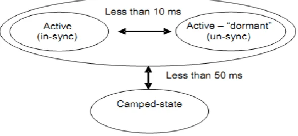
Fig 3: Requirements for state transition
2.4.2 Cost-related requirements
Low cost of the infrastructure deployment and terminal for Advance E-UTRA and Advanced E-UTRAN shall be an essential element. Power efficiency in the infrastructure and terminal shall be essential element. Backhauling shall minimize cost per bit. Advanced UTRA and Advanced E-UTRAN should allow backhaul using LTE spectrum. Further enhancement of SON and self-configuration shall be essential element follow, special care with respect to SON shall be taken for special deployment scenarios like network sharing[17]. Special care with respect to SON shall be taken for mass deployment scenarios like in the case of home eNBs, i.e. for IN and Outbound Mobility for home eNode B and
[image:3.595.148.443.418.553.2]2.4.3 Capability-related requirements
2.4.3.1 Peak Data Rate
The peak data rate is the maximum data rate to be supported from a system requirement viewpoint regardless of radio interface parameters such as the transmission bandwidth and antenna configuration[19]. Advanced E-UTRA should support significantly increased instantaneous peak data rates. At a minimum, Advanced E-UTRA should support the key feature of IMT-Advanced which is stated in the enhanced peak data rates to support advanced services and applications (100 Mbit/s high and 1Gbit/s for low mobility were established as targets for research).
2.4.3.2 C-Plane latency and Capacity
The overall C-plane latency shall be significantly decreased compared. The C-Plane latency takes into account RAN and CN latencies in in unloaded conditions.The target for transition time from Idle mode to connected mode is less than 50 ms including the establishment of the user plane. The target for the transition from a dormant state in Connected mode is less than 10 ms.The system should be able to support at least 300 active users without DRX in a 5 MHz bandwidth.
2.4.3.3 U-Plane latency
The UE does not have a valid scheduling assignment. The UE needs to synchronize and obtain a scheduling assignment. The U-Plane latency as the minimum achievable user plane latency with the system configurations optimized for latency.
2.4.4 System performance requirements
2.4.4.1 Spectrum efficiency
The target for peak spectrum efficiency, the average spectrum efficiency, and cell edge spectrum efficiency are defined. The target for average spectrum efficiency and the cell edge user throughput efficiently should be given a higher priority than the target for peak spectrum efficiency and VoIP capacity. The target for average spectrum efficiency and the cell edge spectrum efficiency should be achieved simultaneously. VoIP capacity should be improved relative to that the evaluation for E-UTRA and E-UTRAN in antenna configuration.
2.4.4.2 Peak spectrum efficiency
The peak spectrum efficiency is the highest data rate normalized by overall cell bandwidth assuming error-free conditions, when all available radio resources for the corresponding link direction are assigned to a single UE The system target to support downlink peak spectrum efficiency of 30 bps/Hz and uplink peak spectrum efficiency of 15 bps/Hz.
2.4.4.3 Average spectrum efficiency
Average spectrum efficiency is the aggregate throughput of all users normalized by the overall cell bandwidth divided by the
number of cells. The average spectrum efficiency is measured in b/s/Hz/cell. Advanced E-UTRA should target the average spectrum efficiency to be as high as possible, given a reasonable system complexity.
2.4.4.4 Cell edge user throughput
The cell edge user throughput is the 5% point of CDF of the user throughput normalized with the overall cell bandwidth. Advanced E-UTRA should target the cell edge user throughput to be as high as possible, given reasonable system complexity. A more homogeneous distribution of the user experience over the coverage area is highly desirable and therefore a special focus should be put on improving the cell edge performance. The system shall support mobility across the cellular network form various mobile speeds up to 350km/h.
3. RESEARCH METHODOLOGY
APPROACH
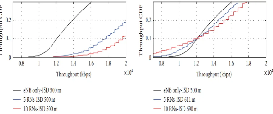
Here the research methodology has been proposed to check the relay impact on system performance from the coverage perspective. In this case, a specific throughput level (10%-tile of throughput CDF)assumed as threshold, while relaying impact will increase the inter-site distance (ISD), which leads tothe cell coverage improvements. The relay node transmission power and ISO-performance curve (also known as indifference map) are the performance metrics[20]. The ISO-performance curve is the set of points, in which each point provides exchange ratio betweenthe eNBs and RNs, promising the same system performance. i.e. 10%-tile of throughput CDF. In order to calculate the iso-performance deployments, an iterative algorithm has been used. The output of this algorithm is the combination of RN with ISD combinations, while the reference scenario is ISD 500meter with eNB only network[21]. In each iteration, one RN is added per sector as well as ISD increased 3upto level, that the new deployment admits the 10%-tile CDF throughput is equal to the reference deployment scenario. This process continues till the maximum numbers of RN per sector aredetermined. Similarly, ISO-performance (also known as indifference map) deployments are used to obtain a trade-off between the number of RNs andeNBs. This trade-off is known as exchange ratio between eNB and RNs while keeping the same system performance level (i.e. 10%-tile of throughput CDF).
Exchange ratio =ρRN/ ∆ρeNB.
1.Similarly, average cell throughput levels give the network capacity gains[22]. Below methodology is used for network capacity oriented comparison.In Type 1b relaying, the backhaul and access link antennas are enough physically isolated. Hence, simultaneous transmission is possible on the both links as well as reduces the limitation on the backhaul link resources. The UE end-2-end throughput calculation can be done as;
3.1 Propagation Models
The radio environment has a large impact on wireless communication system performance. In the study, three different propagation model scenarios have been considered. In propagation,
3.1.1 scenario 1
(Sc1), all the links , Direct link (eNB-UE), Backhaul link (eNB-UE), Access link (RN-UE)are using singles-slope channel models (e.g. Okumura-Hata models). It means that the donoreNB, RNs and UEs are at NLOS to each other. However, practically it is not possible as there is probability of line-of-sight (LOS) conditions for small cell sizes. In propagation,
3.1.2 scenario 2
(Sc2), a dual probabilistic channel models have been proposed where mixedLOS/NLOS modeling for Access link (RN-UE) will be used. The probability function will calculate theLOS/NLOS distance between the UE and RN and will use an appropriate channel model (LOS/NLOS)for the access link. While theDirect link and Backhaul link using the same single slope models. In propagation,
3.1.3 scenario 3
(Sc3), a dual probabilistic channel models are also used for Direct link and Backhaul link. Similarly, the channel models used for access link are the same as used in
3.1.4 scenario 2 Performance
(Sc2).The network consists of regular hexagonal cellular layout with 19 tri-sectored macro cell sites. The simulation has been done for both3GPP Case 1 (urban) and 3GPP Case 3 (sub-urban).For this study,7 RNs and 14 RNs, which constitute, respectively, 1 and 2 tiers are deployed in the network. The first tier RNs are deployed at the cell edge in such a way that there should be minimum coverage gap between neighboring RN cells. Similarly, the second tier RNs are deployed near to the eNB. For indorses, 20 dB penetration losses added on the access link and direct link. The UE link throughput is calculated by given formula,
TPUE=BWeff*M*BWPRB*log2(1+(SINR/SINReff))
Where,
BWeff = Bandwidth efficiency
M = Number of allocated PRBs
BWPRB = Bandwidth of PRB
SINR = UE experienced SINR
SINReff= System SINR efficiency
3.2 Cell Throughput
ISO-Performance (ISD 500m).It is evident from results, that Type 1b RNs have better performance especially at high SINR levels as compared to Type 1 RNs in both RNs deployments types (i.e. 7 RNsand 14 RNs) for scenario 1. The reason is the backhaul link, which bottlenecks the e2e throughput of two-hop link. Moreover, the Type 1b RNs have good performance for scenario 2 as compared to othertwo scenarios while achieving average cell throughput gains.
Fig 4 : ISO-performance curve – ISD 500 m
Considered Scenario Best Exchange Ratio
Type 1 RN Type 1 b RN
Scenario 1 120 93
Scenario 2 30 26
Scenario 3 18 15
[image:6.595.63.503.507.718.2]Table 1: Coverage extension evaluation , ISD 500 m
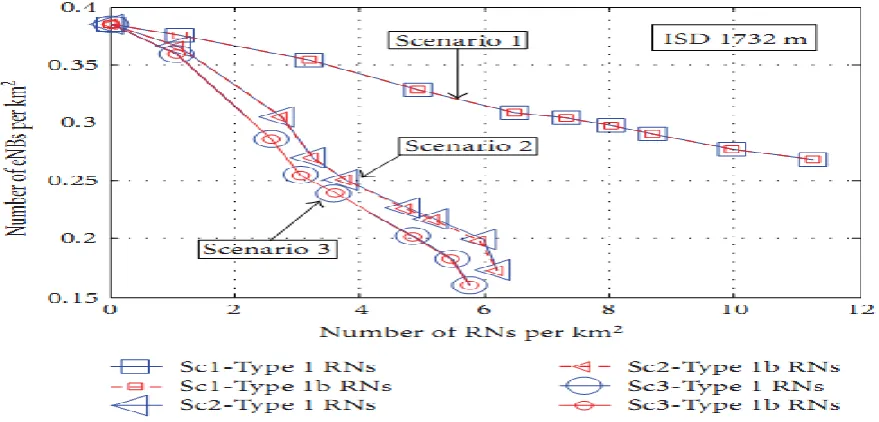
Table 2: Coverage extension evaluation , ISD 1732 m
Considered Scenario Best Exchange Ratio
Type 1 RN Type 1 b RN
Scenario 1 86 86
Scenario 2 28 28
Scenario 3 24 24
4. CONCLUSION
Coverage extension:ISO-Performance (ISD 500m).
The results show that Type 1 and Type 1b have small ISO-performance difference for all three scenarios. Similarly, the required number of RNs in ISO-combination of scenario 3 is less than those in scenario 1 and scenario 2. When comparing scenario 1 & 2, both aresing the same channel models for direct link and backhaul link,but the scenario 2 have good performance then scenario 1. The reason is LOS probability used on the access link give a good performance. Moreover, in case of scenario 2 & 3, the difference occurred due to good performance of direct link as the both the scenario have the same channel models for backhaul and relay link.Hence simulation results show that for scenario 3, both types of RNs gives cost-efficient solution for the coverage extension as compared to other two scenarios.
Coverage extension:ISO-Performance (ISD 1732m).
It can be stated from the results that both types of RNs have the same kind of behavior from coverage perspective. While the system performance for all three scenarios are almost the same, as that for ISD 500m.It has been observed that the exchange ratios decreases for RNs with high transmission powers, mean that less number of high power transmission power relays will be needed to replace eNB in order to get same performance level. For the case, with one time cost (CAPEX and IMPEX), FN backhaul and low cost site, the one-time costs for all types of RNs are always lower than eNBs. The reason for this cost benefit is the high site costsof eNB which mainly include the civil work costs. While the RNs can be easily installed on the street lamp posts which required less site acquisition efforts. Moreover, the consumer grade architecture with low power RNs outperforms the carrier grade architecture due to lower equipment costs. In addition to it, operator can do 30% savings within period of 5 years by deploying RNs insteadofeNB.Similarly, with OPEX, MW backhaul and high cost site, high transmission powers RNs are more favorable as compared to low transmission power. The main dominating parameter is OPEX as the operator will need high number of low transmission RNs as well as the O&M costs will be more than theeNB case. Nevertheless, operator can save more than 30% cost with high transmission power RNs.
5. REFERENCES
[1] Mogensen.P. 2007. LTE Capacity Compared to the Shannon Bound. in Proc. IEEE VTC Spring 2007. pp 123 4-1238.
[2] BouSaleh.A. Riihonen.T. Hämäläinen. J. Redana.s. Raaf.B. Wichman.R. 2009. Performance of Amplify-and-Forward and Decode-and- Forward Relays in LTE-Advanced. IEEE 70th Vehicular Technology Conference (VTC2009-Fall), USA.
[3] Beniero.T. Redana.S. Hämäläinen.J. Raaf.B. 2009.Effect of Relaying on Coverage in 3GPP LTE-Advanced. IEEE VTC Spring.
[4] Lang.E. Redana.s. Raaf.B. 2009. Business Impact of Relay Deployment for Coverage Extension in 3GPP LTE-Advanced. LTE Evolution Workshop, ICC 2009, pp 14-18 .
[5] Mogensen.P.E. Koivisto.T. Pedersen 2009. LTE-Advanced: The path towards gigabit/s in wireless mobile communications. Wireless Communication, Vehicular Technology, Information Theory and Aerospace &Electronic Systems Technology, 2009. Wireless VITAE 2009, pp.147-151 , 17-20.
[6] Yanikomeroglu.H. 2002. Fixed and mobile relaying technologies for cellular networks. in Proceedings of the 2nd Work shop in Applications and Services in Wireless Networks (ASWN ’02), pp. 75–81, Berlin, Germany.
[7] 3GPP TSG-RAN WG., R1-100353. 2010. Comparing In-band vs. Out-band Relays in coverage limited scenario. Nokia, Nokia Siemens Networks, Meeting #59bis, Valencia, Spain, 18. - 22.
[8] Cover.T.M. and El Gamal.A.A. 1979. Capacity Theorems for the Relay Channel. IEEE Transactions on Information Theory. vol. 25, no. 5, pp. 57284.
[9] Saito.T. 2009.Trends in LTE/WimaxSystems, Fujitsu Mag, Vol 45.
[10] Akyildiz.F. Gutierrez-Estevez.M. andChavarriaReyes.E. 2010. The evolution to 4G cellular systems: LTE-Advanced. in: Physical Communication. Volume 3.Issue 4.pp 217-244.
[11] 3GPP TR 36.814 V1.2.1. 2009. Further Advancements for EUTRA: Physical Layer Aspects. Tech. Spec.n Group Radio Access Network Rel. 9.
[12] Parkvall.S. Dahlman.E. Furuskar.A. 2008. LTE-advanced— evolving LTE towards IMT-advanced. in Proceedings of the IEEE Vehicular Technology Conference (VTC ’08) . pp. 1–5.
[13] Yanikomeroglu.H. 2004. Cellular multi-hop communications: infrastructure-based relay network architecture for 4G wire- less systems. In Proceedings of the 22nd Biennial Symposium on Communications , Queen’s University, Kingston, Canada.
[14] Wang.B. Zhang.J. and Høst-Madsen.A. 2005. On the capacity of MIMO relay channels. IEEE Transactions on Information Theory , vol. 51, no. 1, pp. 29–43.
Radio. IEEE Communications Magazine , vol. 42, no. 9, pp. 80– 89.
[16] Le.L. andHossain.E. 2007. Multihop cellular networks: potential gains, research challenges, and a resource allocation frame- work. IEEE Communications Magazine , vol. 45, no. 9, pp. 66– 73.
[17] Wu.H. Qiao.C. De.S. andTonguz. 2001. Integrated cellular and ad hoc relaying systems: iCAR. IEEE Journal on Selected Areas in Communications . vol. 19, no. 10, pp. 2105–2115.
[18] V.Sreng, Yanikomeroglu.H and Falconer.D. 2002. Coverage enhancement through two-hop relaying in cellular radio systems. in Proceedings of the IEEE Wireless Communications and Networking Conference (WCNC ’02). vol. 2,. pp. 881–885.
[19] Irmer.R. andDiehm,.F. 2008. On coverage and capacity of relaying in LTE-advanced in example deployments.
In Proceedings of the IEEE International Symposium on Personal, Indoor and Mobile Radio Communications , pp. 1–5.
[20] Song.Y. 2008. Relay station shared by multiple base stations for inter-cell interference mitigation. IEEE C802.16m-08/1436r1.
[21] Avestimehr.A.S. Sezgin.A.and D.N.C.Ts. 2008. Approximate capacity of the two-way relay channel: a deterministic approach. in Proceedings of the 46th Annual Allerton Confer- ence on Communication, Control. and Computing , pp. 1582– 1589.