O
MEMBRANES
MEMBRANE CONTACTORS: AN INTRODUCTION TO THE TECHNOLOGY
For removal of dissolved gases from an aqueous stream, membrane contactors are operated with the aque-ous fluid flow on one side of a hydropho-bic membrane and a sweep gas and/or a vacuum applied to the other side of the membrane. Since the microporous membrane is hydrophobic, the mem-brane will not allow liquid water to pass through the pore into the gas side of the membrane. The membrane essentially acts as a support between the gas and liquid phases that allows them to inter-face at the pore. By adjusting the partial pressure of the gas in contact with the water, gases can be selectively removed or dissolved into the water.
Theory of Operation
Membrane contactors are typically fab-ricated with hydrophobic hollow-fiber microporous membranes. Since the membranes are hydrophobic and have small pores, water will not easily pass through the pore. The pressure required to force water to enter the pore can be calculated by the Young-Lapace equa-tion modified for use with hydrophobic membranes (1, 2). This pressure is often called the breakthrough pressure (Equation 1).
P = -2σcosθ/r Eq. 1 ver the last 3
years, the de-signs of
micro-ISSN:0747-8291. COPYRIGHT (C) Tall Oaks Publishing, Inc. Reproduction in whole, or in part, including by electronic means, without permission of publisher is prohibited. Those registered with the Copyright Clearance Center (CCC) may photocopy this article for a flat fee of $1.50 per copy.
where:
p = breakthrough pressure, θ = contact angle,
σ = surface tension of the water, and r = radius of pore in microporous mem-brane.
A hydrophobic polypropylene mem-brane with a pore size of 0.05 micron (µm) has a breakthrough pressure that exceeds 150 pounds per square inch gauge (psig). This high breakthrough pressure prevents water from passing through the membrane at pressures below 150 psig. At the pore, the gas phase will be in direct contact with the liquid phase. It is at this interface that gases can be removed or dissolved into the water, depending on the equilibrium condition established.
Principles of Operation
To explain the contactors ability to re-move dissolved gases from water, it is important to discuss the driving force for mass transfer. Henrys law states that the amount of gas that will dissolve into water at equilibrium is proportional to its partial pressure in the vapor-phase in contact with water (3) (Equation 2).
p = Hx Eq. 2
where p = gas partial pressure,
By Fred Wiesler
Hoeschst Celanese Corp.
Membrane contactors are not sensi-tive to flooding, channeling, or back-mixing.
Membrane contactors are modular.
Membrane contactors contain an or-der of magnitude greater surface area per unit volume as compared to conventional columns.
Membrane contactors can use a combination of vacuum and inert gas to create the driving force for mass transfer.
Can be operated over a wide range of flowrates.
System footprint can be custom de-signed and modified.
Smaller overall system design.
Ability to achieve dissolved oxygen levels of 1.0 ppb
porous membrane contactors for gas-transfer applications have rapidly de-veloped. These newly designed contactors have moved the technology from small laboratory-scale devices, lim-ited to 5 to 10 gallons per minute (gpm) capacity, to large-scale industrial de-vices designed for water treatment sys-tems operating at 1,000 to more than 2,000 gpm. Since these devices are relatively new, the technology is often misunderstood. This article discusses the theory and principles of operation of membrane contactors in an effort to give users a better understanding of the tech-nology.
Background
Membrane contactors are devices that allow a gaseous phase and a liquid phase to come into direct contact with each other, for the purpose of mass transfer between the phases, without dispersing one phase into the other. A typical use for these devices is the re-moval or dissolution of gases in water.
The concept of using membranes to bring two phases into contact with one another is not new. However, recent developments in the design of the contactors have greatly increased their efficiency and capacity. These devel-opments have brought membrane contactors out of the laboratory and made them economical for medium- and large-scale industrial uses.
TABLE A
Features and Benefits of the Membrane Contactors
ULTRAPURE WATER® MAY/JUNE 1996--UP130427 H = Henrys law coefficient, a function of
water temperature, and
x = concentration of dissolved solute at equilibrium.
Under one atmosphere and 25 oC, water will contain approximately 8.5 parts per million (ppm) of dissolved oxygen, 14.5 ppm of dissolved nitrogen, some trace amounts of carbon dioxide, and other trace amounts of gases found in the atmosphere. If the partial pressure of the gas in contact with the water is reduced, the amount of gas dissolved in the water will be reduced correspond-ingly. The partial pressure of the gas can be lowered in two ways. The total pressure of the gas phase can be low-ered, or the concentration of the gases in the gas phase can be altered. To lower the total pressure of the gas, a vacuum can be applied to the gas side of the membrane. These same prin-ciples govern the operation of a vacuum tower (4). To alter the concentration of gases in contact with the water, a strip gas that contains little or none of the gas being removed from the water can be introduced into the gas side of the mem-brane. These same principles govern the operation of a forced-draft degasifier. Pore Illustration
Since membrane contactors bring two phases in contact with one another for the purpose of transferring mass be-tween the phases, their performance can be modeled using basic equations used for multistage columns. Their per-formance is typically measured by the ratio of the inlet-dissolved-gas concen-tration to the outlet-dissolved-gas con-centration. Equation 3 (5) illustrates the ratio in its simplest form.
cl/co = e-kaL/vo Eq. 3 where cl = outlet-dissolved-gas con-centration,
co = inlet-dissolved-gas concentration, k = mass-transfer coefficient,
a = surface area, L = length, and
vo = velocity of the fluid.
The mass-transfer coefficient is a term that describes how quickly a mass can move through a medium. The resis-tance to transport can be described as the reciprocal of the mass-transfer coef-ficient. This concept is very similar to that of thermal conductivity and resis-tance in a heat exchanger. The overall mass-transfer coefficient is the sum of
the reciprocals of the individual mass-transfer coefficients. This can be written as shown in Equation 4 (5):
l/kov = l/kl + l/km + l/kv Eq. 4 where kov = the overall mass-transfer coefficient,
kl = the liquid-phase mass-transfer coef-ficient,
km = the membrane mass-transfer coef-ficient, and
kv = the vapor-phase mass-transfer co-efficient.
As a gas molecule diffuses through the water, it must travel around water molecules. As it reaches the pore, it must diffuse through the gas molecules inside the pore and into the other side of the membrane.
Yang and Cussler (6) have published a paper titled Designing Hollow-Fiber Contactors that experimentally verifies that the dominant resistance to mass transfer for oxygen is in the water phase. The gas phase and membrane resis-tances were found to be so much smaller as to be negligible. The correlation for the mass-transfer coefficient for flow
in-side a hollow fiber and outin-side a hollow fiber are listed below. Since the water phase is the dominant resistance, it is understandable that the mass-transfer coefficient can be correlated to the ve-locity of the water in contact with the membrane. These correlations have been published by Reed, Semmens, and Cussler (5) in Membrane Separa-tions Technology, Principles and Appli-cations (Equations 5 and 6).
Water flowing inside the hollow fiber: kd/D = 1.62(d2v/LD)1/3 Eq. 5 Water flowing outside and perpendicu-lar to the hollow fibers:
kd/D = 1.4(dv0/D)1/3 Eq. 6 where k = mass-transfer coefficient, d = fiber diameter (inside for Equation 5 and outside for Equation 6),
D = diffusion coefficient of oxygen in water,
v = actual water velocity, L = length of the contactor, and v0 = superficial water velocity. Performance Data
As can be seen from Equations 5 and 6,
TABLE B
Common Terms Used with Membrane Contactors
Excess sweep: The gas flowrate required to maximize the perfor-mance of the contactor.
Lumen-side: Inside the hollow fiber.
Partial pressure: The pressure ex-erted by a single component of a gas mixture.
Shell side: Outside the hollow fiber.
Shell: The housing containing the membrane contactor.
Solute: Species transferred between phases.
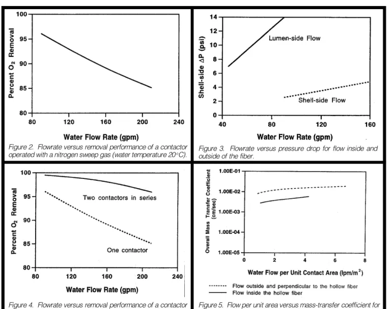
the performance of the contactor can be correlated to the velocity through the contactor, the area of the contactor, the diameter of the fiber, and the diffusivity of the gas in the liquid. For a given contactor design, the performance can be described as a function of the water flowrate. A graph showing the removal performance of a contactor over a range of flowrates is provided in Figure 2.
The efficiency with which a contactor can remove dissolved oxygen from wa-ter is typically used to describe the contactors performance. Oxygen is used because it can be accurately mea-sured and it is the gas most commonly removed from water. The percentage of oxygen removal is defined through Equa-tion 7.
[(Ci - Co)/Ci] * 100 Eq. 7 where Ci = inlet concentration and Co = outlet concentration.
The performance of the device is typi-cally referred to in terms of % oxygen removal. The outlet concentration can be quickly calculated from the inlet con-centration and the % removal value.
When data are presented as the outlet dissolved-oxygen concentration, it is important to know the inlet concentra-tion of the oxygen. For example, water at 25 oC will contain approximately 8.5 ppm of dissolved oxygen, and at 20 oC it will contain approximately 9.1 ppm of dis-solved oxygen. Without knowing the inlet concentration, the % removal of the device is not known.
Contactor Evolution
Early contactors were made of microporous hollow-fiber bundles in a shell-and-tube configuration. The liquid phase was introduced into the inside of the hollow fiber (lumen-side), and the gas phase was introduced on the out-side (shell-out-side). The gas phase flowed parallel to the water phase. This design suffered a major drawback: the hydrau-lic resistance to flow through the inside of the hollow fiber. This resistance cre-ated an unacceptably high pressure drop. The maximum flowrate commer-cially available for these devices was typically around 5 gpm. To accommo-date a higher flowrate with lower pres-sure drop, contactors were placed in parallel to increase capacity.
Initial attempts to increase the indi-vidual capacity of the contactors were unsuccessful. The capacity could be increased by increasing the contact area
or by reducing the waterside pressure drop. The contact area could be in-creased by increasing the bundle diam-eter or the length of the contactor. Fab-ricating a contactor with a large-diam-eter fiber bundle proved to be difficult. The depth of the bundle prevented the potting material from completely filling the voids between the fibers. This made a fragile bundle that did not hold up well over time. Attempts to reduce the water-side pressure drop included increasing the fiber diameter and flowing water on the outside of the fibers. Increasing the fiber diameter adversely affected the amount of contact area that could be packed into the device. Contactors designed with water flow on the outside of the bundles showed poor performance caused by severe flow channeling.
A baffled device that overcame these hurdles was patented1 (7) in 1993. In this design, the hollow fibers are woven into a fabric array. The fabric is wound around a central distribution tube. Dur-ing the windDur-ing process, a baffle is placed at the center of the bundle. This patented design allows water to flow radially across the fiber bundle and be evenly distributed throughout the bundle (Figure 1).
This design reduced the waterside pressure drop through the contactor and allowed additional membrane area to be incorporated into a single device. Fig-ure 3 shows the pressFig-ure drop of the contactor as a function of flowrate. As can be seen from the attached graph, the pressure drop of the contactor with flow inside the hollow fiber is greater than that with flow on the outside of the hollow fiber.
The importance of this reduction in pressure drop is not intuitively obvious. When the pressure drop is reduced, two and three contactors can be placed in series. Placing the contactors in series greatly improves the overall removal ef-ficiency of a contactor train by increas-ing the fluid velocity. Figure 4 shows the performance of one and two contactors in series as a function of flowrate. The slope of the curve representing the per-formance of one contactor has a steeper negative slope than does that of the two contactors in series. This can be ex-plained by reviewing the mathematical equations.
As described in Equation 7, the per-centage of removal is defined as the inlet concentration-outlet concentration/ inlet concentration for one contactor in series. The second contactor in a series
will theoretically have the same removal efficiency. For example, at 100 gpm, the first contactor in series removes ap-proximately 95% of the dissolved oxy-gen. The second contactor in series will remove 95% of the remaining dissolved oxygen, or 99.75%. As can be seen from the graph, the flowrate through two contactors in series can be increased to more than 200 gpm while achieving the same removal efficiency.
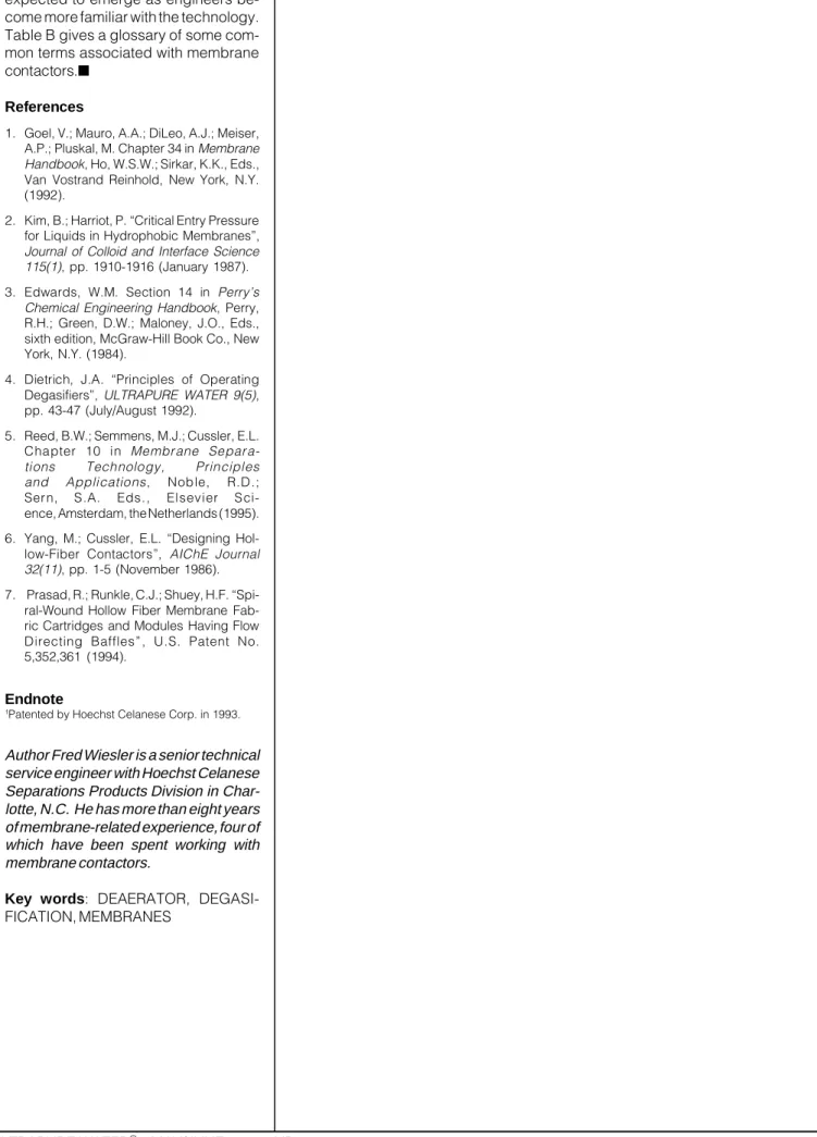
A graph plotting the mass-transfer coefficient as a function of flow per unit area is shown in Figure 5. The actual value for the mass-transfer coefficient is obtained by measuring the performance of the contactor and solving for the mass-transfer coefficient, k. It is interesting to note that the mass-transfer coefficient for a given fiber is higher when the liquid phase is outside the fiber. The en-hanced mass transfer is attributed to the additional turbulence associated with flow across the membrane.
Comparison to Conventional Membrane Filtration
The use of membranes in membrane contactors is very different from how membranes are used for liquid filtration. Filtration devices, used to remove par-ticles and dissolved solids from water, allow the water to pass through the mem-brane; and they exclude particles or dissolved solids from passing through the membrane based on the sizes of those particles or solids. Water pres-sure is used as the driving force to move the water through the membrane, and the pore excludes particles from
pass-ULTRAPURE WATER® MAY/JUNE 1996--UP130427
Figure 3. Flowrate versus pressure drop for flow inside and outside of the fiber.
Figure 5. Flow per unit area versus mass-transfer coefficient for flow outside and perpendicular to fiber, and flow inside fiber. Figure 4. Flowrate versus removal performance of a contactor
for one and two in series operated with nitrogen sweep gas.
ing through the membrane. Reverse osmosis, ultrafiltration, and microfiltration membranes are not capable of remov-ing dissolved gases.
Membranes used for phase-contact purposes have no convective flow across the membrane. A partial pressure gra-dient is used to facilitate the transfer of mass via diffusion from one phase to another. Lowering of the partial pres-sure of the gas in contact with the water allows dissolved gases to be removed or dissolved. Liquid water does not pass through the hydrophobic mem-brane; the membrane is used merely to support the two phases and to allow them to contact one another.
Filtration membranes are typically qualified by the percentage of a particu-lar size of particle or solute that the membrane is capable of removing. Since membrane contactors are essentially devices that bring two phases in contact with one another for the purpose of mass
transfer, their performance is typically measured by the ratio of the inlet-dis-solved-gas concentration to the outlet-dissolved-gas concentration.
The most closely related membrane technologies to the membrane contactors are pervaporation and gas separation. Both of these technologies use nonporous membranes that selec-tively allow only certain species of gases to permeate through the membrane. In contrast, membrane contactors contain microporous membranes. Membrane contactors are nonselective and will al-low all gases to pass through them. Comparison to Existing Technology Vacuum towers work under the same principles as membrane contactors. They are typically tall columns filled with packing or trays and are used to bring a liquid phase in contact with a gas phase for the purpose of removing dissolved gases from the liquid. The liquid runs
from the top of the column down around the packing. The packing creates a large surface area for the gas phase to contact the liquid phase. Membrane contactors perform the same task; how-ever, they bring the two phases into contact at the pore without needing to disperse one phase into the other. Table A lists some benefits of membrane contactors.
Conclusion
These recent developments have en-abled the membrane contactor technol-ogy to progress from the laboratory into large-scale production facilities. The most difficult obstacle to overcome was the reluctance of designers to accept new technology, even though traditional mass-transfer concepts are employed. These devices have become widely accepted in many markets, including the semiconductor, power, and phar-maceutical markets. Other markets are
Figure 2. Flowrate versus removal performance of a contactor operated with a nitrogen sweep gas (water temperature 20 oC).
expected to emerge as engineers be-come more familiar with the technology. Table B gives a glossary of some com-mon terms associated with membrane contactors.■
References
1. Goel, V.; Mauro, A.A.; DiLeo, A.J.; Meiser, A.P.; Pluskal, M. Chapter 34 in Membrane Handbook, Ho, W.S.W.; Sirkar, K.K., Eds., Van Vostrand Reinhold, New York, N.Y. (1992).
2. Kim, B.; Harriot, P. Critical Entry Pressure for Liquids in Hydrophobic Membranes,
Journal of Colloid and Interface Science 115(1), pp. 1910-1916 (January 1987). 3. Edwards, W.M. Section 14 in Perrys
Chemical Engineering Handbook, Perry, R.H.; Green, D.W.; Maloney, J.O., Eds., sixth edition, McGraw-Hill Book Co., New York, N.Y. (1984).
4. Dietrich, J.A. Principles of Operating Degasifiers, ULTRAPURE WATER 9(5), pp. 43-47 (July/August 1992).
5. Reed, B.W.; Semmens, M.J.; Cussler, E.L.
Chapter 10 in Membrane
Separa-tions Technology, Principles and Applications, Noble, R.D.; Sern, S.A. Eds., Elsevier Sci-ence, Amsterdam, the Netherlands (1995). 6. Yang, M.; Cussler, E.L. Designing Hol-low-Fiber Contactors, AIChE Journal 32(11), pp. 1-5 (November 1986). 7. Prasad, R.; Runkle, C.J.; Shuey, H.F.
Spi-ral-Wound Hollow Fiber Membrane Fab-ric Cartridges and Modules Having Flow Directing Baffles, U.S. Patent No. 5,352,361 (1994).
Endnote
1Patented by Hoechst Celanese Corp. in 1993.
Author Fred Wiesler is a senior technical service engineer with Hoechst Celanese Separations Products Division in Char-lotte, N.C. He has more than eight years of membrane-related experience, four of which have been spent working with membrane contactors.
Key words: DEAERATOR, DEGASI-FICATION, MEMBRANES