Journal of Engineering Science and Technology Review 6 (2) (2013) 155-159
Research Article
Design of an Active Automotive Safety System
Y. Wang1,* and Q. Zhang21School of information and Electric Engineering, Panzhihua University, Panzhihua - SiChuan - China 2 College of Mechanical Engineering, Panzhihua University, Panzhihua - SiChuan - China
Received 15 May 2013; Accepted 25 July 2013
___________________________________________________________________________________________
Abstract
With the development of the national economy, the people's standard of living got corresponding improvement, cars has been one of the indispensable traffic tools in many families. An active safety system is proposed, which can real-time detect the vehicle's running status and judge the security status of the vehicle. The system, which takes single-chip microcomputer as the controlling core and combines with millimeter-wave and ultrasonic distance measurement technology, can detect the distance from vehicle to vehicle and judge the security status of the vehicle. The hardware composition of the system and the data acquiring circuit are proposed, the mathematic model for different situation is established, and the controlling algorithm is completed. This system can accurately measure speed and distance between vehicles; the active safety control system can meet the relevant data measurement and transmission requirement; and can meet the functional requirement of the active safety control system
Keywords:distance measurement, single chip microprocessor, hardware system, mathematic model, algorithm design
__________________________________________________________________________________________ 1. Introduction
With the development of the national economy, the people's standard of living got corresponding improvement, cars has been one of the indispensable traffic tools in many families. But as the number of cars increasing, the traffic accident rate due to various reasons is more and more high. Road traffic accident has brought us huge losses, has become a serious social problem in worldwide. One of the main types of accidents due to driver fatigue caused by rear-ends impact compared.In order to reduce the occurrence of such incidents.
The vehicle active safety systems have been studied by Many scholars, the paper [1] discusses the basic methods of distance measurement,Paper [2] [3] [4] [5] [6] have studied the active safety systems for reversing and a reversing radar warning system is proposed based on the ultrasonic measuring principle, it achieved a collision when reversing. Hou has studied automotive active safety systems alarm methods and key technologies[7],Cheng has designed a vehicle active safety systems to avoid traffic accidents[8].The author combines academic work on the basis of the above proposes radar technology-based automotive active safety systems. The vehicles can detection the distance between obstacles in real-time through this system (such as the driving vehicle stop or slow in front and side guardrail), and it also can give the warning messages to drivers to take action as soon as possible. In the meantime when the real-time detection distance has lower than the limit value, the system would automatically start braking system to avoid car accidents. Automotive active safety systems based on radar range and speed. Selection of
millimeter-wave radar, ultrasonic distance measuring sensor, and use AT89S52 as the core of the control system control, eventually design the car’s active safety system.
2. Distance measurement principle
In recent years, with the development of science and technology, radar technology has been widely used in various industries. More typical is the millimeter wave and ultrasonic wave radar transmitter. Millimeter wave refers to electromagnetic waves in the wavelength range between 1 ~ 10mm. and its high resolution and small size of the antenna elements can be adapted to the harsh environment[1]. So the millimeter-wave radar has high precision, anti-interference ability, low elevation performance and small size, light weight and can adapt to all-weather. Ultrasonic wave is generated by mechanical vibration of a frequency higher than the audible acoustic wave frequency range of sound waves, can be transmitted at different speeds in different media, having a strong directivity in the communication process, apt to concentrate energy in a variety of advantage of spread of the type of medium, small attenuation in the transmission process, the reflection ability, having a certain ability to adapt to the harsh working environment, etc. Ranging schematic diagram of shown in Fig. 1 based on the collision avoidance system of the ultrasonic and millimeter-wave radar, mainly include the leading vehicle distance and the measurement of the side barriers.
______________
* E-mail address: [email protected]
ISSN: 1791-2377 © 2013 Kavala Institute of Technology. All rights reserved.
J
estr
JOURNAL OFEngineering Science and Technology Review
our vehicle preceding vehicle lateral obstacles lateral obstacles d
L
L
Fig. 1. Crash-avoidance systems ranging schemes.
2.1 Distance measurement based on radar systems Radar systems emitted outwardly to a sequence of contiguous millimeter wave or ultrasonic through the antenna, and the target is received reflected signal measured using a millimeter wave and ultrasonic propagation medium in the process has encountered an obstacle occurs reflected advantages achieved between the vehicle and the vehicle measurement of the distance. That is the radar generated by the transmitter the high-frequency energy of the certain form; warp our-emitting antenna put energy radiation into the space. When a wave travels in space target a small number of high frequency energy is reflected, to arrive at the receiving antenna, the measuring principle is showing in Fig. 2.
Fig. 2. Basic principle of radar ranging.
Radar transmitter ultrasound or millimeter-wave signals, the receiver receives the target echo signal. By measurement the delay time between the transmitted wave and the echo signal to determine the distance between the radar and the target: Its expression is as follows:
2
/
τ
C
R
=
Wherein: C is the electromagnetic wave propagation velocity in air.
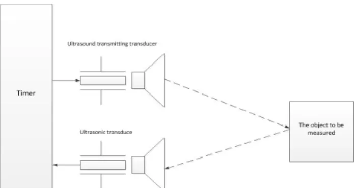
2.2 Distance measurement based on Ultrasonic wave There are many kinds of ultrasonic ranging method, in this paper; we use the round-trip time detection method [2]. Ultrasonic distance measurement principle is shown in Fig.3 [3]. Ultrasonic transmitter emits an ultrasonic wave, at the same time start timing, sound waves spread in the air reflection when it meets obstacles. When the echo signal received by the ultrasonic receiver immediately stop the clock and record the time difference[4]. By following radar ranging system formula can easily get the distance between the two.
Fig. 3. Ultrasonic ranging principles.
But ultrasonic sound velocity changing with temperature is larger. The heat generated by the car in the process of driving will has certain and influence of ultrasonic wave propagation velocity. Thus the measurement error is also relatively large. So under the environment which temperature change a lot need to consider when measuring sound velocity compensation problem. Therefore we should use the sound velocity values in the temperature compensation of velocity formula to fix it[5].
C 331.4 0.607T
=
+
Wherein: C is ultrasonic wave velocity in the medium. m/s;T is the environment temperature. ℃.
3. The system hardware design 3.1 Hardware components
Combination of highway driving in traffic accidents common types, such as rear-ends and side impact. Requirements of the system in the car with the process, the system can have a detection from the vehicle with the front car at the workshop, the lateral distance of the relative vehicle speed is detected with the side of the obstacle, at the same time be able to detect the vehicle speed of the own vehicle, and the detected signal through a certain (display or alarm) feedback to the driver in order to make accurate judgments and take appropriate measures. Or when potentially hazardous conditions exist, within a certain period of time if the driver was not able to take effective measures to avoid the risk, the system will automatically start the emergency braking measures to avoid accidents. From the function of active safety systems requirements analysis. We proposed the active safety system by the millimeter-wave radar, ultrasonic radar range sensor, speed sensor, temperature sensor, microprocessor (MCU), display module, alarm module, the accelerator and brake pedal state detection module and the start of the emergency braking system modules and other components. Among them, the millimeter-wave radar is mainly used for measuring relative velocity and vehicle distance from the car before the workshop. And ultrasonic distance sensor is used to measure the distance from the car with the lateral side of the obstacle car. Braking, throttle state and turn signal acquisition module is used to measure from the vehicle throttle state, steering and braking signal monitoring. Temperature sensor: measure the ambient temperature; Display module: display from the vehicle speed and the vehicle in front car distance and relative speed; alarm module: When the distance between vehicles is less than the safe distance between vehicles prompt the driver to take appropriate emergency
measures to eliminate safety hazards. Brake system startup module: When the alarm module is invalid, the braking system automatically take collision avoidance measures (such as braking, etc.) to avoid accidents. The hardware block diagram is showing in Fig. 4.
MCU input circuit output circuit millimeter-wave radar ultrasonic range finder sensor braking pedal state display module longitudinal alarm module emergency braking system starting muodule temperature sensor transverse alarm module throttle state detection
Fig.4. System hardware block diagram 3.2 The data collection
3.2.1 Millimeter-wave radar signal
The millimeter-wave radar uses a standard RS232 serial communication interface, and when RS-232 communication rate up to 115200 bps (Bit / s), communication distance still can up to 15m, able to meet the needs of the security system. RS232 interface of the system usually use common DB9 interface, that is, for the average two-way communication in the RS-232 communication only need to use a pair of serial input and output ports and ground to meet the communication requirements. It is necessary to achieve the level conversion to complete single-chip data communication and radar when we design RS-232 interface due to the AT89S52 microcontroller input and output level are TLL, but the radar uses a standard serial interface. The level converter chip select the Maxim production MAX232 which will have each drive TTL / CMOS input levels converted to EIA/TIA-232-E level[5][9].
3.2.2 Turn / brake signal acquisition
In order to reduce the false alarm rate and improve the reliability of the system, the driver stepped on the accelerator, brake and steering to implement alarm suppression. Turn signal light is extracted from the vehicle's steering; throttle signal obtained from the accelerator pedal; brake signal is extracted from the brake light circuit. Throttle switch and brake switch are often manipulated by the pedal off switch when the accelerator and brake pedal is depressed, the brake and throttle two switch is turned on, and the switch signal to the microcontroller, the microcontroller via an optically isolated circuit to capture the signal. And it also played an interference shielding of the input switch.
3.2.3 Ultrasonic signal acquisition
Ultrasonic Ranging signal acquisition mainly set by the microcontroller I / O port emits a 40MHz square wave signal to drive the ultrasonic transducer to emit ultrasonic signals after the drive circuit, and the microcontroller start timing. When the transducer received echo pulse signal, amplified by the circuit transmitted to the microcontroller, the microcontroller receives the signal, an interrupt and stop the
clock, read the time difference between the transmitted wave and the echo signal to calculate the distance.
4. Software Design
4.1 Longitudinal mathematical model
The system safe distance model is designed to ensure that the system can work to reduce operational errors due to misjudgment. Thus ensuring a safe driving to avoid a vehicle with a rear-end collision, side collision, the driver can adjust the relative vehicle speed and increase the longitudinal inter-vehicle distance to achieve. In order to ensure the concept of taking measures to stop the two vehicles not to collide, then the introduction of the minimum safety distance (d0), has a
very important significance. In order to simplify the mathematical model to make a basic assumption: all vehicles have the same braking performance. Vehicle safety distance has a very close relationship with its braking distance[6-7]. Its braking distances formula as follows:
)
2
(
2
max 0 2 1 2 0 s h xt
t
t
v
a
v
v
d
=
−
+
+
+
Since the relative relationship of the car and the vehicle in front, the safety distance can be according to the following three types discussed: the vehicle stationary in front, the brake of the vehicle in front, the vehicle in front constant speed or accelerating.
4.1.1 The vehicle stationary in front
When the vehicle stationary in front, the two-car rear-end may be the time that vehicle’s speed reduce to 0 and the former vehicle is nearest. If there is no collision from the vehicle to decelerate to zero, the possibility of collision will be 0. Safe distance should be the automatic distance plus a safe distance (d0).Its danger alarm distance calculation
formula: 0 0 max 2 1 2 0
)
2
(
2
d
t
t
t
v
a
v
v
d
s h x b+
+
+
+
−
=
Taking into account the distance traveled in the driver's reaction time, its hazard warning distance should be as follows: 0 0 max 2 1 2 0
)
2
(
2
d
t
t
t
v
a
v
v
d
s h x w+
+
+
+
−
=
4.1.2 The vehicle braking in front
When this car suddenly braking with the process, there may be three different cases dangerous moment. The vehicle in front stops first, and the car stops after; the two vehicles stopped at the same time; since the first car stopped, stop the vehicle in front. After the car in front began to emergency braking, the own vehicle once measured the relative speed has reduced through radar, the own vehicle collision avoidance system starts the function of warning or braking. The corresponding calculation formula is as follows:
0 0 max 2 1 2 0
)
2
(
2
d
t
t
t
v
a
v
v
d
s h x b+
+
+
+
−
=
Taking into account the distance traveled in the driver's reaction time, its hazard warning distance should be as follows: 0 0 max 2 1 2 0
)
2
(
2
d
t
t
t
v
a
v
v
d
s h x w+
+
+
+
−
=
4.1.3 the vehicle in front with constant speed or accelerating
When the automative does uniform motion or accelerated motion, the most dangerous moment is when the speed of our vehicle is the same to the preceding vehicle. At the moment, if the rear-end collision doesn’t happen, it couldn’t happen. Because our vehicle still does retarded motion, and the preceding vehicle retains its motion state. In this condition, the distance between the two vehicle is becoming far and far. So, the key is to avoid the rear-end collision when the two vehicle have the same speed. The computing equation of reminding alarm distance is following:
0 max 1 max 2 1 2 0
2
)
2
(
2
a
d
v
v
t
t
v
a
v
v
d
s rel x rel b+
+
−
+
−
=
Considering the driving distance in the responsing time of driver, the dangerous alarm distance can be computed by the above equation.
0 max 1 max 2 1 2 0
2
)
2
(
2
a
d
v
v
t
t
t
v
a
v
v
d
s rel h x rel w+
+
+
−
+
−
=
The above formulas are obtained with the car in front driving uniform motion, if the former car is doing accelerated motion, still using the above formula, the system will be more secure.
Where: d is the braking distance; dw is alarm distance; db is dangerous distance; d0 is minimum safety distance; v0 is the own vehicle speed; v1 is the former vehicle speed; tx is braking coordination time; ts is the time to brake to slow down; vrel is the relative speed; th is drivers’ action time; amax is maximum braking acceleration.
4.2 The transverse model
System by ultrasonic sensors measure the distance between the own vehicle and on both sides of obstacle, and we know whether the distance between the both sides is in the safe range basic on the measurements results. If it is out of the safe range the system will take actions (system alarm) to warn the driver. Minimum side distance and the travel speed of the car have a close relationship. Its expression is shown defined as follows:
200
40
94
.
0
0 min=
+
V
−
L
The side distance under the speed should faster than the minimum safe side distance with the speed that must be met:
min
L
L
≥
4.3 Program design
System software design uses the integrated development environment. It sets the program edit, compile, link, debug
and simulation as a whole, has a friendly interface. Of active safety systems software mainly consists of the main program, millimeter-wave radar transceiver, and ultrasonic transceiver procedures.
4.3.1 The main program design
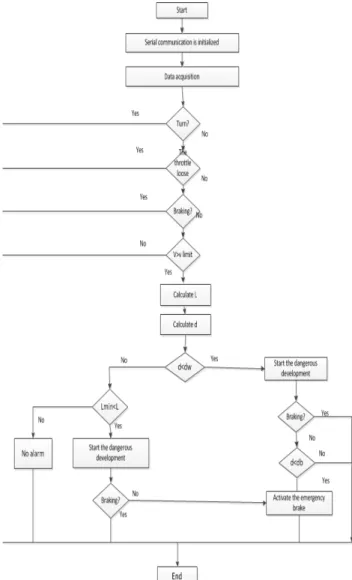
The main program to realize the system initialization, millimeter-wave radar and ultrasonic measurement sensor data and calculate the speed of the corresponding distance value and the vehicle in front. And the vehicle determines whether to enter the high-speed active safety systems. Into the system after the safe distance between vehicles and the calculated data to determine the current vehicle distance d (L) is less than the safe distance between vehicles dw (Lmin). Then enters analyzing mode, determining this safe distance from the vehicle in order to determine whether the alarm. When the distance between vehicles is less than a certain limit braking distance db, start braking system [8-9], the flow chart shown in Fig. 5.
Fig. 5. Block diagram of the system main program
4.3.2 MCU and millimeter-wave radar data exchange The hardware design of MCU and millimeter - wave radar is accomplished through the rs-232 standard serial communications port measurement of data transfer. MCU and millimeter-wave radar data transfer related parameters and data exchange must be initialized before. For example: Timer, the operating mode of the serial port, baud rate settings, the pointer initialization data send [8]. MCU
maintained when the data transmission in the millimeter-wave radar set parameters corresponding to the reception state, and waits for the data transmission request and response, and receive data.
4.3.3 Ultrasonic signal acquisition program
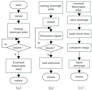
Ultrasonic signal acquisition program mainly consist of the main program, ultrasonic subroutine occurs and the receiving the interrupt service routine. Respectively, as shown in Fig.s 6 a, b, c. The main key to achieve its system initialization, such as the setting of the timer works, start to interrupt allowed and the transmit subroutine is mainly used to generate a square wave signal of 40MHz to drive transmitting transducer engender ultrasonic signal, and start the counter. Which receives the interrupt program is mainly used for detecting the ultrasonic echo signals of an external interrupt, once the echo signal is received, the process proceeds to interrupt Off Timer and read the value of the timer to complete the calculation of the corresponding distance.
5. Conclusion
By analyzing the automotive active safety system functional requirements, AT89S52 microcontroller to control the core, combined with radar measurement technology and design of the active safety systems, proposed system hardware solution, a mathematical model and the corresponding control program is designed algorithm design. The system is able to meet the real-time detection of the vehicle state data,
such as speed, vehicle information; and timely determination of the vehicle security status and feedback status information to the driver, while the system is able to be played when necessary to avoid safety accidents, thus improve the vehicle's active safety performance.
external Interruput
inlet
shut interrupt
read clock time
compute range open interrupt return timing interrupt inlet initial Emission signal end emission return initial timing interrupt inlet External Interruput inlet return start return? finish? Y Y N N (a) (b) (c)
Fig. 6. Ultrasonic signal acquisition programs
______________________________ References
1. Zhong,Y., “Four Distance Measuring Methods for Modern Motor Vehicles”,Auto Industry Research2(2),2001, pp. 38-40.
2. Huang,L.-P.,He J,-P.,Ni, L.,Lin,L.-J., “Design and Implement ation of Visible Reversing Radar Alert System”,Computer Measurement & Control18(1),2010, pp. 150-156.
3. Li,S.-P., “Design of Ultrasonic distance measuring system based on MCU AT89S52”,Automation & Instrumentation(6),2009, pp. 44-47.
4. Zhou,W.,Zeng,L-H.,Lu,K.,“Research of Electronic Parking Radar Based on Ultrasonic Ranging System”,Computer Measurement & Control12(4),2004, pp. 349-351.
5. GUO,Q.,“Ultrasonic Ranging and Anti-collision System Based on STC89C52”,Instrument Technique and Sensor,2011(6). pp. 349-351.
6. LI,W.-M.,“Ultrasonic range finder based on STC89”,Journal of Shaanxi Normal University: Nat Sci Ed(33), 2005, pp. 27-32. 7. Hou,D.-Z et al.,“The Warning Algorithm and Some Key
Technologies of Vehicle Collision Avoidance System”, Automotive Engineering(5), 2002, pp. 434-441.
8. Cheng,Z.-ZH.,Wu,J.-L.,“Zhou Binfeng.Research on Automobile Anti -collision Safety System”,Machinery47(9),2009, pp. 36-38. 9. Sha.ZH.-Y. et al., “Design of peripheral circuit of singlechip(