Design and Implementation of an Integrated Remote
Test System for Mobile Phones
Ying-Wen Bai and Chia-Yi Chang
Department of Electronic Engineering, Fu Jen Catholic University, Taipei, Taiwan, 242, R.O.C. [email protected]
Abstract- In this paper we design three programs, the first one
is an automatic network RF signal measurement (ANRSM), the second one is automatic RF module and baseband hardware device self-diagnosis SmartMobileTest, and the last one is RF remote control test program (RRCTP). The greatest advantages of our ANRSM and our SmartMobileTest are that they are of a small size with portability, and that they reduce both the test time and the complexity of RF test programs. Our ANRSM is written in C++ language. This program uses the embedded 3GPP RF Spec TS 51.010 and by means of Virtual Instrument Software Architecture (VISA) controls the General Purpose Interface Bus (GPIB) which is used to control the RF base station simulator. Moreover we use LabVIEW and Web publishing technology to develop RRCTP to implement the remote control and command exchange. The SmartMobileTest program is created on a Windows Mobile OS to test the function of the RF and baseband module. Both our ANRSM and our SmartMobileTest support RF automatic testing and detection for the hardware performance of all the RF and baseband modules in a Smartphone. By combining these two programs we are able to identify the effect of both RF sensitivity and noise quickly.
Keywords: Smartphone, 3GPP, Noise, Sensitivity, Reliability
I. INTRODUCTION
In recent years hand-held Personal Digital Assistant (PDA) devices and mobile phones have undergone constant evolution from the original simple PDA and mobile phone, both of which are equipped with the Windows Mobile and Symbian system, and have developed into a Smartphone and a PDA phone, together with 3.5G, which is now the mainstream of communication systems. As the number of functions of mobile phones has increased significantly, a Smartphone is now available loaded with wireless communication specifications such as Bluetooth, WiFi, GPS and others. The addition of these features has made the original mobile phone within the RF communication system more complicated [1, 2]. At the same time mobile phones in the design and development stage also have to deal with potential noise between various RF communication modules [3]. Windows mobile phones are an example of an entity which supports programs operating in background mode. Whether the RF sensitivity of a mobile phone while it is placing a call will be affected is an important factor which is worthy of our consideration. There are situations where a mobile phone is being used, and meanwhile simultaneously in the background mode either Bluetooth, WiFi, GPS, Camera, or the SD reader are operating or the LCD panel is turned on. In such a situation, with the mobile phone in
the talk state, the RF sensitivity is affected by noise interference which in this paper is the important factor for our consideration [4, 5].
Electronic assembly and testing include two basic types: the PCB board test and the product functional test. The PCB board test mainly measures the RF baseband signals to find out the PA to the antenna before the end of the baseband signal. The result of this test decides whether the transmitter power is good or not, but the naked version connects with the antenna module. As the overall RF performance must closely suit the user’s needs, with a mobile phone the RF performance testing of the final products is a must [6, 7]. Due to the rapid development of computer communications, many of the high-speed data buses are used to test and measure applications. However, each data bus has its advantages and disadvantages, which we must consider when making an appropriate choice for the type of application under examination. GPIB is an 8-bit (Bit) parallel digital communication interface with a data transmission speed of up to 1 Mbyte/s. This bus can not only support the controller but can also be very effectively used between the control apparatus and for communication between the computers, and is often chosen as the system for an equipment GPIB automation control connector. Most RF automated testing programs use the GPIB to control the measurement instrument. As those programs must install their company’s IO Library first to both access measurement test result images and create the database, the programs are large, and their portability is low. In addition, they are expensive [8].
In this paper we create an RF automatic test program written in C++ language and apply the Smartphone test to the PCB board. This test program identifies the impact factor on RF sensitivity quickly. We have named this program, which is very small, and requires only 440KB, ANRSM. This program, which controls the GPIB by means of VISA, is quickly installed and started in a computer in which a VISA Library is already installed.
Measurement of RF performance is highly complex. Each measuring channel handover needs to realize rapid remote automated measurement and remote operation of the debug. This complicated procedure can affect the shipping time of mobile phones. Therefore, in this paper, we use a very small test program for rapid automated RF measurement with embedded 3GPP regulations which provide a judgment of “Pass” or “Fail” and have both a portable and supporting
IEEE International Symposium on Industrial Electronics (ISIE 2009) Seoul Olympic Parktel, Seoul, Korea July 5-8, 2009
remote operation. We thus can carry out a remote real-time RF debug under the automatic measurement system. In this paper we use the Visual Studio 2005 environment with C++ language both to write an ANRSM for the integration of the RF tester, GPIB and VISA, and to write the Windows Mobile system for the implementation of the RF and baseband module hardware. The self-diagnosis program is for the hardware and software control functions, and embeds both the 3GPP RF Spec TS 51.010 and the RRCTP into the ANRSM, thus allowing the program file to run in the Web browser to the remote control and to debug the instrument remotely. Our program carries out an RF automatic test, a self-diagnosis, remote control and operation functions.
II. THE HARDWARE ARCHITECTURE
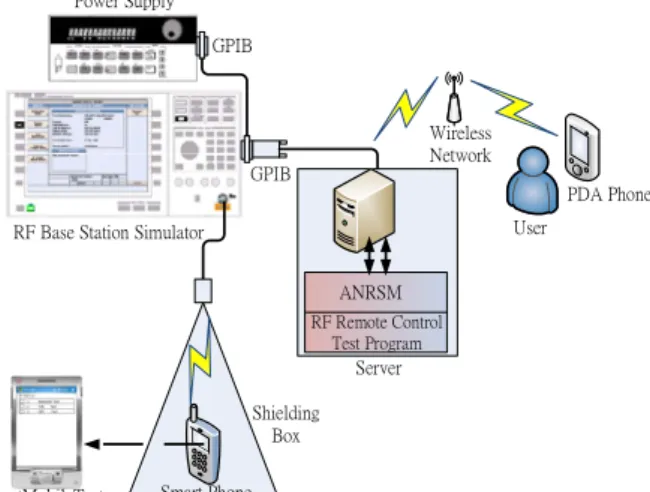
Fig. 1 shows the architecture of the remote automatic RF measurement system which consists of the following parts: the RF base station simulator, a power supply, a shield box and the RF test software (ANRSM, RF SmartMobileTest, and RRCTP).
The remote RF automatic measurement system allows the user to operate through the Internet anywhere in the world, at any time, remotely operating and remotely debugging RF measurement instruments. After setting the RF parameters in the test program from the client user, the server controls the GPIB cable by means of the VISA and then controls the RF base station simulator and the power supply. The role of the RF base station simulator is to provide an RF signal to the shielding box and to send the signal to the mobile phone. Our design can simulate the 2G and 3G environments in talk mode (condition 1) for RF signal measurement, with Bluetooth, WiFi, GPS or a camera still working in the background mode (condition 2) of a Windows mobile system. We combine these two conditions and then use our test programs to test and analyze the RF performance, to determine whether the test result is “Pass” or “Fail”, and then to save the result either to the CSV or to a text file. The remote controller monitors the test status and the results in real-time and carries out real-time
debug.
III. THE SOFTWAREARCHITECTURE
We build the software part with Visual Studio 2005 which provides C#, C++, MFC, Java and other programming languages. This part, which includes the Windows mobile system simulator, can simulate the popular built-in Windows mobile 5 and Windows mobile 6 Smartphone systems. In addition, we choose C++ to develop a Windows mobile system program and use the MFC for ANRSM development.
VISA is a single interface library used to control GPIB, VXI, RS-232 and other apparatus. VISA is a VXI alliance standard plug and play system. VISA functions, VISA open, VISA write, VISA read and VISA closed, can be described as follows.
The architecture diagram in Fig. 2 shows that VISA, when applied in a program, interacts and coordinates with the surrounding software.
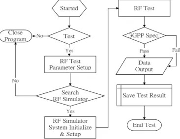
Fig. 3 shows the flow chart of the ANRSM. The system first asks the user to set the RF parameters. Then the system begins to search for the existence of the RF base station simulator. If the simulator does not exist, the program displays an error message on the screen, asks the user to confirm whether the address of the RF base station simulator is correct and then leaves the program. If the program finds the RF base station simulator, it initializes the simulator, sets the user’s parameters to the instrument and then sets up the call procedures. The program first sends commands from the simulator to allocate a telephone call to the mobile phone, and then automatically waits until it receives the call from the mobile phone. The RF measurements start tests, such as the Tx power and Rx sensitivity test, and measure data from the collation and publishing functions to compare with the embedded 3GPP specification. To determine either “Pass” or “Fail” for the real-time display of measured values and results on the screen of the test program for user reference, the user can save the test result either as a simple text file or as an Excel file on the Power Supply
RF Base Station Simulator
Wireless Network User PDA Phone GPIB GPIB ANRSM RF Remote Control Test Program Server Smart Phone Shielding Box SmartMobileTest
Fig. 1. The architecture of Remote RF automatic test system.
Fig. 2. The architecture of the ANRSM.
computer for future reference and for ease in the setting up of a database.
We design a built-in automatic testing program in the Smartphone device. Our program supports both automatic testing and the hardware component function testing tool; the program’s advantages help both R & D designers, testers and production line testers reduce the test time and the testing complexity. Our design for RF and baseband modules applications includes a GPS module, a WiFi module, a Bluetooth module, a camera, an SD and a speakerphone module for mobile phone designers, manufacturers, production line testing and the user. These application modules have a relatively great importance because they directly affect the sensitivity quality of the mobile phone. These modules are the most frequently requested items. This automatic testing program also provides for component reliability testing to give the user mobile phones of better quality. We name this program SmartMobileTest, and apply it to RF Rx sensitivity measurements using the Windows Mobile system with RF and a baseband module for turning on or off such modules as
Bluetooth, GPS, WiF or camera. By viewing these functions our program measures the specific noise which is interfering with the quality of the Rx sensitivity. We also acquire knowledge of all the indirect effects on the sensitivity of the Rx.
The SmartMobileTest development tools have been designed with Visual Studio 2005 in order to develop a man-machine interface. Visual Studio 2005, which has the ability to develop a Windows mobile phone program, can be installed on the Windows mobile phone with the exact same simulation features of the simulator. Fig. 4 shows the development process. We install the Visual Studio 2005 development program and develop smart mobile devices required by the SDK package, such as the Windows mobile 5.0 pocket PC SDK, the Windows mobile 6 SDK and the .NET Framework SDK 2.0. A C + + language program is developed for the initial set-up in order to be the first detector of any hardware
modules. Each hardware functional test item uses a modular approach to set up programs written in the corresponding modules. Each module in its implementation with the Windows Mobile communication cooperates with the Windows mobile hardware detection feature to assure normal operation.
The way we use the original complex architecture and simplify and streamline it is shown in Table I. Each level supports its upper-level operation; the top level can be controlled by the lower level and the lower level returns the test results to the top-level control layer. Fig. 5 shows the SmartMobileTest software architecture.
TABLE I
SOFTWARE LAYER OF THE SMARTMOBILETEST
Level Explanation User Interface Controls every test module and creates the test result on the OS.
Control Layer Received by the user interface layer command,executes immediately and communicates to the OS, then drives the device.
Communication Layer
The communication layer is the medium responsible for passing messages between the control and hardware device layers. Hardware
Device Layer
Distributed in the smart mobile device within the hardware components such as Bluetooth, GPS, WiFi, Camera, Speakerphone, and SD card. Fig. 3. The flowchart of the ANRSM .
Fig. 4. The develop process of SmartMobileTest.
Fig. 6 shows the SmartMobileTest design for normal mode and the RF module automatic test mode. When the Smartphone boots into the Windows Mobile OS for the SmartMobileTest program implementation, we can choose whether or not to execute the RF module diagnosis. If the Smartphone does not enter into the diagnosis it will enter into the normal mode. If we choose to enter into the diagnosis, the SmartMobileTest will be executed and we can choose the RF or other hardware modules to execute the test. At the same time the program
automatically links to the required testing, the RF module function transfers code to carry out the test, and the test procedures are displayed on the cell phone screen. After the test is completed, the program shows the test results on the mobile phone display and selects the next module function
transfer code to test the module.
Fig. 7 shows the ANRSM and SmartMobileTest combined into the remote RF automatic test system flowchart.
We use the SamrtMobileTest tool to add the option to test when either the Bluetooth, the WiFi, the GSP, the camera, speaker, or the SD card are on.
We use LabVIEW to design a user interface to remotely control the RF base station simulator and plug it into the IE
browser to remotely control the device. In the design we use the Web publish function to exchange both data and commands between the server and any client. We develop a VI program by using LabVIEW and embed the program in the IE browser in the server. The user can use any Smartphone, PDA, PC or notebook with a browser device to link to the IP address to easily obtain the browser RF remote control interface.
We can use the interface of the browser to remotely control the instrument and for an immediate remote debug. The IE browser embedded in a PDA phone is used to link the RRCTP program by 3G data networks or WiFi to remotely access the server further in order to control the RF test anywhere in the world.
Fig. 8 shows the RRCTP embedded in the IE browser and developed with LabVIEW version 8.6. In this program we can choose the test item in the browser area on the right for the user to speedily and easily set up the parameters in the remote
instrument.
Fig. 9 shows the implementation result in the remote instrument and the control by the remote operator interface.In Fig. 9(a), when we press the Power vs. Time button, we can obtain the Fig. 9(b) waveform from the remote instrument.
We use the Bit Error Ratio (BER) test to obtain the Rx sensitivity value. Fig. 10 shows how to measure the BER. The RF base station simulator will generate a Pseudo random binary sequence (PRBS), modulate via the antenna to the Smart phone turn on RF and baseband module automatic test mode Normal mode Set SmartMobile Test function Yes No Display test process Display test Pass /Fail Next function test Get transfer code Get next test function code No End RF test Yes SmartMobile Test
Fig. 6. The flowchart of SmartMobileTest..
Fig. 7. Combine the ANRSM and SmartMobileTest into the RF automatic test system flowchart
Fig. 8. The remote operator interface of the RRCTP.
(a) (b)
cellular phone and demodulate into the speech coder. After the speech coder finishes processing the PRBS will then modulate via an antenna to the RF base station simulator. After the RF base station simulator receives this sequence, the sequence is then demodulated; the new PRBS is compared with the original PRBS and then calculated to generate the BER value.
In the test program design we reduce the PRBS data from
1,640,000 to 10,000 bits to reduce the time of the BER test. When we reduce the PRBS data it impacts the error rate of measurement. For our design it has generated an 0.05dBm error rate when we reduce the PRBS data to 10,000 bits.
IV. IMPLEMENTATION RESULTS
Fig. 11 shows the ANRSM user interface and its three test items, the Rx sensitivity test, the Tx power test and the Phase & Freq error test. When testing, the user can choose either one or two items to test. The lower left area in the system contains the function key for setting up the test parameters, the data save key, the clean Log key, the pause key, the stop key and the start key. If we press the parameter key, the sub-program displays the user interface and lets the user create the test plan.
The sub-program respectively not only tests the band, the channel and the power control level choice but also can control
two different instrument functions. This sub-program allows the user to create the RF test plan easily.
Fig. 12 shows the Smartphone user interface of the SmartMobileTest. It includes the Bluetooth, the WiFi, the GPS, the camera, the speaker and the SD card test. And the user can choose either a single function or up to six functions to test.
When we choose the camera and SD test item, our test program can let the camera module continue work in the background or let the SD read and write data for a long time in
order to make sure those hardware modules both function and work correctly when we conduct the all channel sensitivity test. Our test program’s main objective is to help the ANRSM to find the Rx noise.
Figs. 13 and 14 show the test result of our design of the remote RF automatic test system. The test has been carried out under conditions where the modulation is GMSK and the test talk mode receiver sensitivity is within the required DCS of 1800MHz. When testing the Smartphone’s receiver sensitivity we add the following conditions: camera on, WiFi on, Bluetooth on, display on, micro-SD on, and speakerphone on.
Fig. 13 shows that the Smartphone’s receiver sensitivity is bad when the user opens the camera. Fig. 13 shows that sensitivity of channel 605 decreases from an ideal of -103.6dBm to -96.9dBm, a decrease of 6.7dBm.
We increase the thickness of the RF shielding case to contact with the back cover’s metal of the Smartphone to reduce the noise. Fig. 14 shows that the sensitivity of channel 605 increases from -96.9dBm to -101.6dBm and its sensitivity improves by 4.7 dBm.
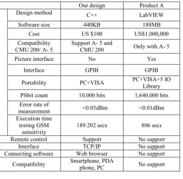
Table II shows the comparison of our design with Product A. We can see that our design has a smaller program volume than Product A. As for compatibility, our design shows compatibility with two different kinds of RF instruments, but Product A can control only one. As for portability, our design can run on any device that includes a VISA library but Product
Fig. 10. The block diagram of Bit error ratio test.
Fig. 11. User interface of the ANRSM.
-108 -107 -106 -105 -104 -103 -102 -101 -100 -99 -98 -97 -96 512 527 542 557 572 587 602 617 632 647 662 677 692 707 722 737 752 767 782 797 812 827 842 857 872 Se ns it iv ity (d B m ) Channel GSM 1800-RX Sensitivity
On-call (GMSK) +Wi-Fi… +Wi-Fi… +micro-SD
+Speakerphone +Display on +Bluetooth +Camera
Fig. 13. GSM 1800MHz Receiver Sensitivity.
Fig. 12. User interface of the SmartMobileTest.
A only can run on a device with a Product A IO library. As the testing time of our design uses 10,000 pseudo sample bits to test, therefore our design is 4.2 times faster than Product A,
although its measurement error rate is only 0.01dBm. For remote control our design supports an IE browser which can be remotely controlled by either a Smartphone, a PDA phone or a PC device.
TABLE II
COMPARISON OF OUR DESIGN WITH PRODUCT A
Our design Product A
Design method C++ LabVIEW
Software size 440KB 188MB
Cost US $100 US$1,000,000
Compatibility CMU 200/ A- 5
Support A- 5 and
CMU 200 Only with A- 5
Picture interface No Yes
Interface GPIB GPIB
Portability PC+VISA PC+VISA+5 IO Library
PSbit count 10,000 bits 1,640,000 bits
Error rate of measurement <0.05dBm <0.01dBm Execution time testing GSM sensitivity 189.202 secs 806 secs
Remote control Support No support
Interface TCP/IP No support
Connecting software Web browser No support
Compatibility Smartphone, PDA phone, PC No support
V. CONCLUSION
We use C++ language to design a test program, ANRSM that automatically tests RF performance. We also develop a SmartMobileTest in the Windows mobile phone that automatically tests both RF and the various baseband modules like Bluetooth, GPS, WiFi, Camera, Speakerphone and SD card. We coordinate these two test programs to measure the receiver sensitivity, thus helping the designer to improve the sensitivity without any delay. We test the sensitivity of all channels, and to improve the test speed we modify the sample count from 1,640,000 to 10,000. We can see by this experiment
that although we decrease the number count of statistics to 10,000 we are still able to accurately identify the effect of the RF receiver sensitivity factor. Our program also improves the measurement’s reliability. Most automatic programs are designed with LabVIEW that loads the necessary VISA and GPIB driver, implements the LabVIEW program in the local computer with the LabVIEW development software, and then runs the automatic test program. Because our program has been developed with C++ language and includes the VISA library, it is small, requiring only 440KB, and has high portability, so that it can be executed on any device that has both a VISA and a GPIB driver. Thus our program is of great help to the designer in enhancing the efficiency of the product line by reducing the testing time of a RF receiver.
Most automatic test programs are only executed in local instrument servers for automatic control, but they do not provide remote control through the Internet. We use the Web publish function to plug the RRCTP into a Web browser to let the user remotely control the RF instrument. The main objective is to allow engineers all over the world to cooperate easily by means of a Web browser both to remotely debug and to reduce the development time of a Smartphone.
REFERENCES
[1] Yiweih Zhang, Xiaohui Duan, Jingjie Wang, and Laixian Zhang, “Design and Implementation of Wireless Monitoring System Based on Windows Mobile”. 4th International Conference on Wireless Communications, Networking and Mobile Computing, WiCOM '08, pp.1-4, 12-14 Oct. 2008.
[2] Zhao Ying and Wang Zhiyun, “Design of Embedded Display Control Terminal Based on Windows Mobile 5.0,” 8th International Conference, on Electronic Measurement and Instruments, ICEMI '07, pp. 288 - 2-291, Aug. 16 2007-July 18 2007.
[3] Eun-Pyo Hong, Yong-Seok Hwang, and Hyung-Joun Yoo, “A Low Power Folded RF Front-end with Low Flicker Noise for Direct Conversion Receiver,” IEEE Conference on Electron Devices and Solid-State Circuits, EDSSC 2007, pp. 222-226, 9-11 Dec. 2007.
[4] J. Dobes snd Z. Kolka, “Mobile handset and radiation power absorption measurement, IEEE Region 10 Conference on TENCON 2007, pp.1-4, Oct. 30 2007-Nov. 2 2007.
[5] Guan-Yu Chen, Cheng-Hung Lin, Jwo-Shiun Sun, Kwong-Kau Tiong, and Y. Chen, “Enhanced Modes of the Sensitivity Analysis for RF Design,” International Symposium Signals, Systems and Electronics, ISSSE '07, pp.83-86, July 30 2007-Aug. 2 2007.
[6] Ying-Wen Bai and Chin-Chung Lee, “Design and Implementation of an Automatic Testing System for MP3 Players,” IEEE Instrumentation and Measurement Technology Conference Proceedings, IMTC 2008, pp.2205-2210, May 2008.
[7] Lei Xiaoyong, Sheng Wen and A. Jia Mingjie, “Design of Remote Measurement System Based on Hybrid Bus,” 8th International Conference on Electronic Measurement and Instruments, ICEMI '07, pp.1-990 - 1-993, Aug. 16 2007-July 18 2007.
[8] Han Xiaoru and Gao Yudong, “Design and Implementation of the Universal RS232-GPIB Interface,” 8th International Conference on Electronic Measurement and Instruments, ICEMI '07, pp. 3-220 - 3-223, Aug. 16 2007-July 18 2007.
[9] G. Drenkow, “Future test systems architectures,”, IEEE Instrumentation & Measurement Magazine, Vol. 8, pp.16-21, Aug. 2005.
-108 -107 -106 -105 -104 -103 -102 -101 -100 512 527 542 557 572 587 602 617 632 647 662 677 692 707 722 737 752 767 782 797 812 827 842 857 872 Se ns it iv ity (d B m ) Channel GSM 1800-RX Sensitivity
On-call (GMSK) +Camera +Wi-Fi… +Wi-Fi…
+micro-SD +Speakerphone +Display on +Bluetooth
Fig. 14. After increase the thickness of RF shielding case GSM 1800 MHz receiver sensitivity