Computer Science Dissertations Department of Computer Science
5-6-2019
Multicast Aware Virtual Network Embedding in
Software Defined Networks
Evrim Guler
Georgia State University
Follow this and additional works at:https://scholarworks.gsu.edu/cs_diss
This Dissertation is brought to you for free and open access by the Department of Computer Science at ScholarWorks @ Georgia State University. It has been accepted for inclusion in Computer Science Dissertations by an authorized administrator of ScholarWorks @ Georgia State University. For more information, please [email protected].
Recommended Citation
Guler, Evrim, "Multicast Aware Virtual Network Embedding in Software Defined Networks." Dissertation, Georgia State University, 2019.
NETWORKS
by
EVRIM GULER
Under the Direction of Xiaojun Cao, PhD
ABSTRACT
The Software Defined Networking (SDN) provides not only a higher level abstraction
of lower level functionalities, but also flexibility to create new multicast framework. SDN
decouples the low level network elements (forwarding/data plane) from the
control/man-agement layer (control plane), where a centralized controller can access and modify the
configuration of each distributed network element. The centralized framework allows to
de-velop more network functionalities that can not be easily achieved in the traditional network
services from the underlying hardware infrastructure to allow the same Substrate (Physical)
Network (SN) shared by multiple Virtual Network (VN) requests. With the network
virtual-ization, the process of mapping virtual nodes and links onto a shared SN while satisfying the
computing and bandwidth constraints is referred to as Virtual Network Embedding (VNE),
an NP-Hard problem. The VNE problem has drawn a lot of attention from the research
community.
In this dissertation, we motivate the importance of characterizing the mode of
commu-nication in VN requests, and we focus our attention on the problem of embedding VNs with
one-to-many (multicast) communication mode. Throughout the dissertation, we highlight
the unique properties of multicast VNs and explore how to efficiently map a given Virtual
Multicast Tree/Network (VMT) request onto a substrate IP Network or Elastic Optical
Networks (EONs). The major objective of this dissertation is to study how to efficiently
embed (i) a given virtual request in IP or optical networks in the form of a multicast tree
while minimizing the resource usage and avoiding the redundant multicast tranmission, (ii) a
given virtual request in optical networks while minimizing the resource usage and satisfying
the fanout limitation on the multicast transmission. Another important contribution of this
dissertation is how to efficiently map Service Function Chain (SFC) based virtual multicast
request without prior constructed SFC while minimizing the resource usage and satisfying
the SFC on the multicast transmission.
NETWORKS
by
EVRIM GULER
A Dissertation Submitted in Partial Fulfillment of the Requirements for the Degree of
Doctor of Philosophy
in the College of Arts and Sciences
Georgia State University
NETWORKS
by
EVRIM GULER
Committee Chair: Xiaojun Cao
Committee: Anu Bourgeois
Jonathan Shihao Ji
Yi Zhao
Electronic Version Approved:
Office of Graduate Studies
College of Arts and Sciences
Georgia State University
DEDICATION
I dedicate this work to my beautiful wife (Tugba Guler), son (Arda Guler), and my
beloved family.
ACKNOWLEDGEMENTS
This dissertation work would not have been possible without the support of many people.
I want to express my gratitude to my dear advisor Dr. Xiaojun Cao, for believing in me at
first, staying behind me at difficult times, and guiding me with his expertise. I would also
like to thank each of my committee members - Dr. Anu Bourgeois, Dr. Jonathan Shihao Ji,
and Dr. Yi Zhao, for their guidance and encouragement.
A special note of thanks to all my professors, back in Turkey at Ege University, the
University of Michigan-Flint and Georgia State University who contributed to my growth,
both personally and professionally. Finally, I take this opportunity to thank all my good
friends, especially Yasin, Berkay, Ahmet, Deniz, Murat, Rahim, Olcay, Bayram, Harun and
ACKNOWLEDGEMENTS . . . v
LIST OF ABBREVIATIONS . . . xii
PART 1 INTRODUCTION . . . 1
1.1 Software Defined Networking . . . 2
1.2 Network Function Virtualization . . . 4
1.3 Virtual Network Embedding . . . 5
1.4 Multicast Virtual Network Embedding . . . 8
PART 2 RELATED WORK . . . 10
2.1 Virtual Network Embedding (VNE) . . . 10
2.1.1 VNE over IP Networks . . . 10
2.1.2 VNE over Optical Flexible Networks . . . 12
2.2 Multicast Virtual Network Embedding (MVNE) . . . 14
2.2.1 MVNE over IP Networks . . . 14
2.2.2 MVNE over Optical Flexible Networks . . . 16
PART 3 MULTICAST-AWARE VIRTUAL NETWORK EMBED-DING PROBLEM FORMULATION . . . 18
3.1 Substrate Network . . . 18
3.2 Virtual Multicast Tree . . . 19
3.3 Multicast Data Transmission Request . . . 19
3.4.1 Node Mapping . . . 20
3.4.2 Link Mapping . . . 21
3.5 Virtual Multicast Tree Embedding Problem . . . 22
PART 4 MULTICAST-AWARE VIRTUAL NETWORK REQUEST EMBEDDING . . . 23
4.1 Closeness-Centrality based Multicast Virtual Network Embedding 25 4.1.1 Virtual Node Mapping . . . 30
4.1.2 Virtual Link Mapping . . . 31
4.1.3 An Example of CC-MVNE . . . 32
4.1.4 Experimental Results . . . 34
4.2 Chapter Summary . . . 37
PART 5 VIRTUAL MULTICAST TREE REQUEST EMBEDDING 38 5.1 Virtual Multicast Tree Embedding with Dynamic Impact Factor 40 5.1.1 Virtual Node Mapping . . . 43
5.1.2 Virtual Link Mapping . . . 46
5.1.3 An Example of VMTE-IF . . . 46
5.1.4 Experimental Results . . . 48
5.2 Impact Factor Based Virtual Optical Multicast Tree Embedding 52 5.2.1 Virtual Node Mapping . . . 57
5.2.2 Virtual Link Mapping . . . 60
5.2.3 An Example of IF-VOMTE Algorithm . . . 61
5.2.4 Experimental Results . . . 63
5.3 Chapter Summary . . . 66
PART 6 DEGREE-BOUNDED MULTICAST-AWARE VIRTUAL RE-QUEST EMBEDDING . . . 68
6.2 Virtual Optical Request . . . 70
6.3 Multicast Service Embedding in EONs with Fanout Limitation. 70 6.3.1 Node and Link Mapping . . . 70
6.4 Centrality-based Degree Bounded Shortest Path Tree . . . 74
6.4.1 An Example of C-DB-SPT Algorithm . . . 78
6.5 Experimental Results . . . 80
6.6 Chapter Summary . . . 83
PART 7 MULTICAST-AWARE SERVICE FUNCTION TREE EM-BEDDING . . . 84
7.1 Substrate Network . . . 86
7.2 Virtual Request . . . 87
7.3 Multicast Service Function Tree Embedding (M-SFTE) . . . 87
7.3.1 Node Mapping . . . 87
7.3.2 Link Mapping . . . 88
7.4 Minimum Cost Multicast Service Function Tree . . . 89
7.4.1 Level-based Path Splitting . . . 90
7.4.2 Minimum Cost Pair Selection . . . 92
7.4.3 An Example of MC-MSFT . . . 94
7.5 Experimental Results . . . 96
7.6 Chapter Summary . . . 99
PART 8 CONCLUSION . . . 100
Table 2.1 Classification of Multicast Virtual Network Embedding . . . 10
Table 4.1 Network Simulation Parameters of CC-MVNE Performance . . . . 36
Table 6.1 Notations for the C-DB-SPT Algorithm . . . 73
Table 7.1 The Substrate Network . . . 86
Table 7.2 Notations for the MC-MSFT Algorithm . . . 90
Figure 1.1 SDN Architecture: conceptual planes and communication interfaces 2
Figure 1.2 Hardware-based appliances for network services such as Firewall, Deep
Packet Inspection (DPI), Virtual Private Network (VPN), IPTV, to
software-based NFV solutions . . . 5
Figure 1.3 Next Generation Network Model: Network virtualization . . . 6
Figure 1.4 The process of Virtual Network Embedding . . . 7
Figure 1.5 Unicast and Multicast Transmission . . . 8
Figure 4.1 Resource wastage in MVNE . . . 24
Figure 4.2 Flowchart of CC-MVNE Algorithm . . . 26
Figure 4.3 The mapping result of CC-MVNE . . . 33
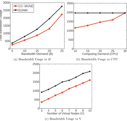
Figure 4.4 Performance results of bandwidth usage while varying B, CP U and V . . . 34
Figure 4.5 Performance results of used hops while varying B, CP U and V . 35 Figure 5.1 Redundant multicast transmissions for Multicast Tree Embedding 39 Figure 5.2 The mapping result of VMTE-IF . . . 47
Figure 5.3 Performance results of bandwidth, hop, and redundancy while varying B . . . 48
Figure 5.4 Performance results of bandwidth, hop, and redundancy while varying V . . . 49
Figure 5.5 Redundant transmission from Multicast Virtual Optical Network Em-bedding . . . 53
Figure 5.6 The mapping process of IF-VOMTE with B = 2 . . . 61
Figure 5.7 Results of spectrum and hop usage, and redundancy while varyingB 63 Figure 5.8 Results of spectrum and hop usage, and redundancy while varyingV 64 Figure 6.1 Fanout limited multicast service . . . 69
Figure 6.2 The mapping process of the C-DB-SPT . . . 78
Figure 6.3 Performance results of spectrum usage while varying V, M B and F 80 Figure 6.4 Performance results of used hops while varying V, M B and F . . 81 Figure 7.1 Multicast Service Function Tree . . . 85
Figure 7.2 The mapping process of MC-MSFT . . . 95
LIST OF ABBREVIATIONS
• SDN - Software Defined Networking
• NFV - Network Function Virtualization
• SN - Substrate (Physical) Network
• VN - Virtual Network
• VNE - Virtual Network Embedding
• VMT - Virtual Multicast Tree/Network
• EONs - Elastic Optical Networks
• API - Application Programming Interface
• REST - Representational State Transfer
• NFVI - Network Function Virtualization Infrastructure
• COTS - Commercial-Off-The-Shelf
• VNF - Virtual Network Function
• N-PoPs - Network Point of Presences
• DPI - Deep Packet Inspection
• VPN - Virtual Private Network
• InPs - Infrastructure Providers
• VNO - Virtual Network Operator
• VNM - Virtual Node Mapping
• VLM - Virtual Link Mapping
• MVN - Multicast Virtual Network
• MVNE - Multicast-Aware Virtual Network Embedding
• VMTE - Virtual Multicast Tree Embedding
• EGNM - Enhanced Greedy Node Mapping
• CC - Closeness-Centrality
• IF - Impact Factor
• CC-MVNE - Closeness-Centrality based Multicast Virtual Network Embedding
• VMTE-IF - Virtual Multicast Tree Embedding based on dynamic Impact Factor
• VOR - Virtual Optical Request
• SON - Substrate Optical Network
• SFL - Substrate Fiber Link
• VONE - Virtual Optical Network Embedding
• MVONE - Multicast-Aware Virtual Optical Network Embedding
• VOMTE - Virtual Optical Multicast Tree Embedding
• IF-VOMTE - Impact Factor based Virtual Optical Multicast Tree Embedding
• VNA - Virtual Network Assignment
• CPU - Central Processing Unit
• MR - Multicast Request
• GNM - Greedy Node Mapping
• FF - First Fit
• CF - Candidate Factor
• RCM - Redundancy Checking Mechanism
• FFNM-SP - First Fit Node Mapping with the Shortest Path
• GNM-SP - Greedy Node Mapping with the Shortest Path
• MSE-FL - Multicast Service Embedding in EONs with Fanout Limitation
• C-DB-SPT - Centrality-based Degree Bounded Shortest Path Tree
• GN-DB-SPT - Greedy Node Mapping and Degree Bounded Shortest Path Tree
PART 1
INTRODUCTION
Computer networks are generally constructed from a large number of network devices
(e.g., routers, switches and different types of middleboxes that manipulate traffic for purposes
other than packet forwarding such as a firewall) implemented by many complex protocols [1].
To realize a wide range of network applications and events, network operators have the
re-sponsibility of configuring network policies and transforming these high-level policies into
low-level commands to manage network devices while adapting to dynamically changing
real network conditions. In addition to network policy configurations, the network
opera-tors need to manage very complex tasks with limited access to the network tools. Hence,
the management and performance tuning of network systems are quite challenging while
vertically-integrating network devices exacerbates the network operations and
administra-tions.
Morever, the invincible/unsurmountable network challenge to be faced by network
oper-ators or researchers is referred to as ”Internet Ossification,” which has the huge deployment
base and is considered the main part of critical physical infrastructure such as the
trans-portation and power grids. Thus, the Internet has become extremely difficult to be evolved in
terms of its physical infrastructure, protocols and performance. However, emerging current
Internet applications and services has become more complex and dynamically demanding
that is able to evolve to address new network challenges.
To facilitate the network evolution, the new idea of ”Programmable Networks” has been
proposed as ”Software Defined Networking” in which the forwarding hardware is decoupled
1.1 Software Defined Networking
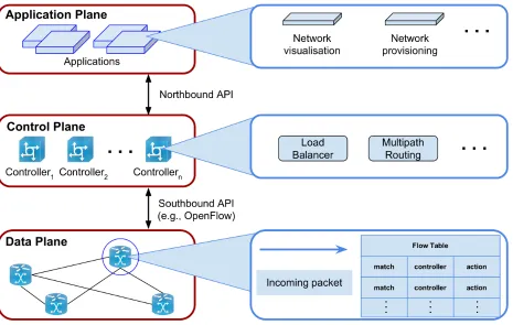
Software Defined Networking (SDN) defines a new concept to design and manage
com-puter networks. The SDN has two defining characteristics as shown in Fig. 1.1: (i) an
SDN decouples the control plane, which manages how to operate the traffic, from the data
plane, which forwards the traffic flow based on the decisions of a control plane, (ii) an SDN
consolidates the centralized control plane to handles multiple data plane elements [2]. The
SDN control plane practices directly operation over the state in the network elements of the
data plane (i.e., routers, switches, and other middleboxes) via a well-defined Application
Programming Interface (API) (i.e., OpenFlow [3]).
Figure (1.1) SDN Architecture: conceptual planes and communication interfaces
In Fig. 1.1, the architecture of SDN introduces three conceptual planes and
communi-cation interfaces, which are (i) applicommuni-cation plane, (ii) control plane, and (iii) data plane. The
[image:19.612.76.541.307.602.2]modifications regarding network aspects (i.e., network policies and routing behavior). The
control plane provides control logics (i.e., routing schemes) to manage the collected
informa-tion from the switches of the data plane such as flow statistics. In the control plane, we have
the global view of the network system to be able to make traffic distributions and enforce
Quality of Service policies. In the data plane, the physical devices are responsible to forward
data when the OpenFlow switches have programmable flow tables that can be dynamically
configured by the control plane.
Furthermore, to occur the communication between the planes, the northbound API
en-ables to program network controller by abstracting the network data with REpresentational
State Transfer (REST) protocol. On the other hand, the southbound API implements the
communication between control plane and data plane to configure switches with forwarding
actions based on received notifications of incoming packets from the data plane by using
OpenFlow protocol.
As a consequence of the SDN principles, the separation of network policies implemented
in switching hardware and the forwarding of traffic is key to provide the flexibility by
break-ing the network control problem into the tractable pieces, and introduce new abstractions
in networking by simplifying network management and facilitating network evolution and
innovation [4]. The SDN and OpenFlow, even though, started as academic experiments [2],
most vendors of commercial switches currently supports OpenFlow API in their equipment.
As an example, Google has a deployed SDN to interconnect its data centers across the globe
by helping the company to improve operational efficiency and significantly reduce costs [5].
With the development of Software Defined Networking, service providers are interested
in facilitating deployment of new network services by abstracting network devices and
appli-ances to fill specialized roles such as routing, switching, spam filter, load balancer, firewall,
and so forth. Integrated with SDN, the Network Function Virtualization (NFV) is proposed
to address flexible provisioning, deployment and centralized management of virtual network
functions while offering agile traffic steering and joint optimization of network functions and
1.2 Network Function Virtualization
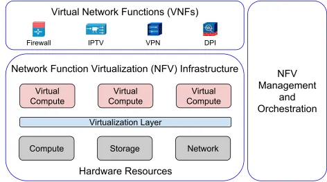
Network Function Virtualization (NFV) separates software instance from hardware
plat-form and decouples the functionality to provision more flexible and faster network service
while transforming the management of underlying network infrastructure by leveraging the
virtualization technology [6]. Essentially, NFV implements and runs network functions (i.e.,
well-defined functional behavior such as firewall, deep packet inspection, virtual private
net-work, etc.) on the hardware (i.e., industry standard servers, storage and switches) through
software virtualization, as shown in Fig. 1.2. To implement lower cost agile network
infras-tructure as an innovative step, the benefits of NFV can dramatically change the landscape of
telecommunications industry. The NFV may reduce capital investment and energy
consump-tion by consolidating networking appliances, decrease the time to market of a new service
by changing the typical innovation cycle of network operators (e.g., through software-based
service deployment), and rapidly introduce targeted and tailored services based on customer
needs.
NFV reduces the equipment cost and forming a strong, scalable and elastic network
ecosystem while decreasing the time to market. Firstly, the NFV is minimizing the spent
time on a new service evaluation and testing for automated Network Function Virtualization
Infrastructure (NFVI) management and orchestration. Next, NFV allows to run software
based network functions on Commercial-Off-The-Shelf (COTS) hardware rather than
pur-pose built hardware for network operators and service providers. NFV network ecosystem
also builds general purpose and cheap infrastructure, where the software based functions
(i.e., Virtual Network Functions (VNFs)) can be executed on middle-boxes. To place VNFs
on the Network Point of Presences (N-PoPs) of the underlying network and construct VNF
chain in a particular sequence are to achieve better network performance while providing as
least good service provision as the original proprietary hardware [7].
In other words, SDN and NFV provide programmable network control and flexible
Firewall
NFV
Management
and
Orchestration
Virtual Network Functions (VNFs)
Network Function Virtualization (NFV) Infrastructure
Virtual Compute
Virtual Compute
Virtual Compute
Virtualization Layer
Compute Storage Network
Hardware Resources
IPTV VPN DPI
Figure (1.2) Hardware-based appliances for network services such as Firewall, Deep Packet Inspection (DPI), Virtual Private Network (VPN), IPTV, to software-based NFV solutions
share the same physical infrastructure while reducing the CAPEX and OPEX, and increasing
the physical resource utilization [8]. The network virtualization also has an important role to
support simultaneously multiple architectures for the future Internet and a major challenge
how to deal with efficient usage of physical network resource for multiple tenants, referred
as virtual network embedding.
1.3 Virtual Network Embedding
The primary entity in the network virtualization is a Virtual Network or Request (VN).
A VN is a combination of active and passive network elements (virtual network nodes and
links) on the top of a Substrate Network (SN). Each virtual node in a VN is interconnected
through a virtual link to form a virtual network topology. By virtualizing both node and
link resources of an SN, multiple virtual network topologies with widely varying
[image:22.612.67.539.73.336.2]introduced abstraction by the resource virtualization mechanism allows network operators to
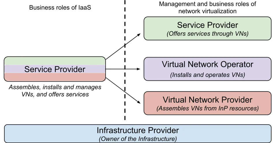
highly flexible (or dynamically) manage and modify network systems. The introduction of
network virtualization separates the management and business roles of the Service Provider
(SP) by identifying three main players as shown in Fig. 1.3: (i) the Virtual Network Provider
(VNP) which assembles virtual resources from one or more Infrastructure Providers (InPs),
(ii) the Virtual Network Operator (VNO) which installs, manages and operates the VN
ac-cording to the needs of the SP, and (iii) the SP which is free of management and concentrates
on business by using the VNs to offer customized services.
Infrastructure Provider
(Owner of the Infrastructure)
Service Provider
(Offers services through VNs)
Virtual Network Operator
(Installs and operates VNs)
Virtual Network Provider
(Assembles VNs from InP resources)
Service Provider
Assembles, installs and manages VNs, and offers services
Business roles of IaaS Management and business roles of network virtualization
Figure (1.3) Next Generation Network Model: Network virtualization
The problem of embedding virtual networks in a shared substrate network is the main
resource allocation challenge in network virtualization and referred to as the Virtual
Net-work Embedding (VNE) problem, where the benefit gained from existing hardware can be
maximized while mapping of virtual resources onto physical hardware. Optimal resource
allocation, leading to self-configuration and organization of next generation networks, will
[image:23.612.67.540.274.523.2]Virtual Network Request (VNR1) Virtual Network Request (VNR2) 2
5 3
7
4 5 1 3
8 1
3
9
9
7 6
4
9 5
3
Physical (Substrate) Network Virtual nodes
Physical nodes Node capacity Link capacity 9
4
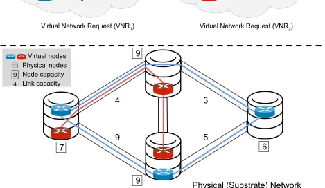
Figure (1.4) The process of Virtual Network Embedding
The VNE problem deals with the allocation of virtual resources both in nodes and links
as shown in Fig. 1.4. Therefore, the problem generally includes two important subprocesses:
(i) Virtual Node Mapping (VNM) and (ii) Virtual Link Mapping (VLM). In the former subprocess, virtual nodes have to be allocated in substrate (physical) nodes that
provide sufficient computing resource. In the latter subprocess of VNE, each virtual link
in VN is mapped onto a substrate (physical) path by reserving sufficient bandwidth (or
subcarriers). Solving optimally VNE problem is NP-Hard, as it is related to the multi-way
separator problem [9]. Even with a given virtual node mapping, the problem of optimally
allocating a set of virtual links to substrate paths reduces to the unsplittable flow problem
[image:24.612.72.541.154.426.2]gained for small problem instances, and currently main focus of work within the research
community is on heuristic or meta-heuristic approaches.
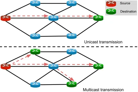
1.4 Multicast Virtual Network Embedding
Many schemes have been proposed to address the general VN mapping problem for
uni-cast services (e.g., [11–15]) to efficiently design provisioning strategies for such VN requests.
Unicast transmission
Multicast transmission
SourceDestination
Figure (1.5) Unicast and Multicast Transmission
However, in many widely used applications, emerging distributed file systems, big data
and Internet applications such as IPTV, video-conferencing, live stock quotes demand
mul-ticast communication to improve the utilization of the physical resource. Unlike the unicast
service where a single sender transmits data to a single receiver, multicast service requires
[image:25.612.75.542.229.541.2]can share the data transmission along the common links (e.g., [16–19]), as shown in Fig. 1.5.
In other words, handling multicast communication as unicast requires transmitting multiple
copies of same data to reach each receiver from same source. Thus, to handle a
one-to-many communication as multicast, these multiple unicast transmission can be replaced by
a single multicast transmission while reducing the computation effort at the same source,
bandwidth consumption in the network, and improving the throughput of applications with
the response time. Thus, supporting multicast service for high traffic in cloud providers is
essential in their data centers. To this extent, multicast service in data center network has
become prominent research topic with focusing the resource allocation problem Multicast
Virtual Networks (MVNs) [20]. The problem of network resource allocation consists of VNM
and VLM processes. While allocating network resources is widely discussed for unicast VNs,
embedding MVNs is greatly different than unicast services. In MVNs, the routing of a traffic
flow from a source to multiple receivers (destinations) consists of constructing a multicast
distribution tree to avoid redundant traffic.
Therefore, in this work, the Multicast-Aware VNE (MVNE) or Virtual Multicast Tree
Embedding (VMTE), Multicast Service Embedding with Fanout Limitation (MSE-FL) and
Multicast-aware Service Function Tree Embedding (M-SFTE) problems have been defined
by minimizing required resource allocation in substrate networks while reducing redundant
multicast data transmission, satisfying the fanout limitation and functionality requirements,
PART 2
RELATED WORK
2.1 Virtual Network Embedding (VNE)
2.1.1 VNE over IP Networks
The VNE problem is known to be NP-hard [9]. Hence, many researchers have
investi-gated efficient heuristic and meta-heuristic approaches [11–15].
The authors in [11] introduce the algorithm design to solve on-demand VN assignment
problem, which is upon the arrival of a VN request, assigning its topology to the substrate
network to achieve low and balanced load on both substrate nodes and links, namely VN
assignment without reconfiguration I) and VN assignment with reconfiguration
(VNA-II) problems. For the VNA-I problem, where the VN assignment is fixed throughout the
VN lifetim, the authors develop a basic scheme to achieve near optimal substrate node
performance and use it as a building block for all other advanced algorithms. For the
VNA-II problem, a selective VN reconfiguration scheme that prioritizes the reconfiguration for the
most critical VNS is developed to achieve most performance benefits of the reconfiguration
without excessively high cost.
In [12], the VN embedding problem by proposing a more flexible substrate network
to better support virtual network embedding is rethought. The flexibility of the substrate
network includes path splitting and migration. Path splitting (i.e. multipath) has been a
recurring theme in many network research topics, and the authors demonstrate the power
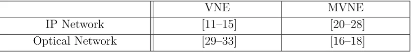
Table (2.1) Classification of Multicast Virtual Network Embedding
VNE MVNE
IP Network [11–15] [20–28]
[image:27.612.100.514.656.709.2]of multipath in substrate network for more cost-effective virtual network embedding while
attaining better resource utilization.
Policy-based inter-domain VN embedding (PolyViNE) framework to heuristically
ad-dress the inter-domain VN mapping problem is investigated in [13]. The authors introduce
policy-based end-to-end VN embedding framework that embeds VNs across multiple InPs
in a globally distributed manner while allowing each concerned InP to enforce its local
poli-cies. PolyViNE introduces a distributed protocol that coordinates the participating InPs
and ensures competitive pricing through repetitive bidding at every step of the embedding
process.
In [14], ViNEYard proposes a collection of VN embedding algorithms to leverage
bet-ter coordination between node mapping and link mapping. ViNEYard algorithms include
Deterministic VN Embedding (D-ViNE), Randomized VN Embedding (R-ViNE), and their
extensions. The major contributions of the algorithms:
• D-ViNE and R-ViNE are two rounding-based VN embedding algorithms that increase
the VN request acceptance ratio and InP revenue without incurring additional cost by
leveraging coordinated node and link mapping
• D-ViNE-LB and R-ViNE-LB are extensions to D-ViNE and R-ViNE that focus on
balancing load across substrate resource to improve the acceptance ratio, often causing
inflated link utilization across the substrate network
• A generalized window-based VN embedding (WiNE), which allows batch processing of
VN requests, is a mechanism for equipping any existing online VN embedding algorithm
with lookahead capabilities
• ViNEYard model presents a flexible and extensible mathematical programming
formu-lation of the VN embedding problem
Path-based Integer Linear Programming (ILP) model for VNE problem (P-VNE) is
in [15]. Based on the dual formulations of the P-VNE model, a column generation process is
presented, which can be embedded into a branch-and-bound framework to effectively resolve
VNE problem optimally in practice.
2.1.2 VNE over Optical Flexible Networks
As Virtual Optical Network Embedding (VONE) problem known to be NP-Hard [34],
many researchers have explored efficient heuristic or meta-heuristic approaches to solve the
VONE problem [29–33].
In [29], the authors study a dynamic traffic scenario by using an auxiliary graph model
to address the multilayer optical network embedding while minimizing bandwidth
block-ing ratio in three possible underlyblock-ing substrates for inter-datacenter networks, namely an
optical-layer-based, electrical-layer-based and multilayer-based (optical and electrical layer)
substrate network. For the node mapping, the applied policies select a node with different
wavelength or electrical resource distribution by setting the adjacent edge’s weight of the
node in the auxiliary graph (AG). Similarly, different link-mapping policies can also be
de-signed by adjusting weights of the edges of the AG. Hence, the main contribution of the
AG in [29] is to provide a general approach for addressing a dynamic VNE over multilayer
optical networks.
The Alignment and Consecutiveness-Aware Transparent Virtual Network Embedding
(ACT-VNE) algorithm in [30] uses consecutiveness-aware node ranking to measure node
capacities for the mapping process in transparent VNE (t-VNE). The algorithm takes into
account the spectrum alignment and consecutiveness between adjacent fiber links while
map-ping virtual nodes onto the substrate nodes. The authors also propose an extended scheme,
namely Importance, Alignment and Consecutiveness-aware Transparent Virtual Network
Embedding (iACT-VNE) that assigns virtual nodes to substrate nodes within close
proxim-ity to establish connections with less bandwidth utilization.
The authors in [31] present Integer Linear Programming (ILP) formulations and a
accommo-date the Virtual Optical Request (VOR) over a transparent optical substrate network. The
Virtual Optical Network Allocation (VONA) is solved over transparent and opaque services
while validating the benefits of exact ILP and GRASP against simpler VONA techniques.
The dynamic transparent virtual network embedding algorithm, which considers node
and link mapping jointly, is proposed for network virtualization over optical orthogonal
frequency-division multiplexing (O-OFDM) based elastic optical infrastructure in [32] in
order to minimize VOR blocking probability. For each VOR, the algorithm first transfers
the substrate optical network into a layered-auxiliary-graph according to the spectrum usage
of each fiber link. In the next step, a node mapping is applied by considering the local
information of all substrate nodes, and the link mapping is accomplished in a single layer of
auxiliary graph.
A static and dynamic versions of virtual topology mapping problems based elastic
opti-cal networks have been explored in [33]. The authors propose ILP model and two heuristic
approaches, which are greedy based First Fit (FF) and Link List (LL) algorithms, to
maxi-mize the subcarrier utilization while minimizing blocking ratio for dynamic traffic. The FF
algorithm maps a virtual node with the lowest index value from a VOR onto a substrate
candidate node that has enough available resource with the lowest index value. On the other
hand, the LL algorithm considers both node requirement and their bit rate request and sorts
virtual and substrate nodes with their connected bit rates of links in decreasing order. After
completing the ordering, the algorithm maps a most constrained virtual node in the virtual
node list onto a substrate node with the highest order.
The majority of these existing V(O)NE approaches targets on the point-to-point
(uni-cast) data traffic. With the rising demand on simultaneous bulk data transfer and the
support to path multiplicity from network topologies have made multicast necessary and
2.2 Multicast Virtual Network Embedding (MVNE)
With more Internet applications demanding multicast transmission such as IPTV,
video-conferencing and live stock quotes, Multicast VNE (MVNE) recently attracts much attention
to transmit the same content from one or multiple starting points through multiple end
points.
2.2.1 MVNE over IP Networks
In [20–28], the works try to minimize the resource allocation on SN to satisfy only
multicast VN requests.
The authors in [21] propose the mapping problem in the context of Virtual Multicast
service-oriented Network subject to Delay and Delay Variation Constraints (VMNDDVC)
and define an efficient heuristic algorithm to tackle the problem based on a sliding window
approach while minimizing the cost of VMNDDVC request mapping and achieving the load
balancing to increase the accepting ratio of Virtual Multicast Network (VMN) request. In
order to meet these constraints in VMNDDVC, a sliding window method is proposed to
construct a set of feasible paths and solve the problem based on feasible paths.
In [22], a multicast mapping algorithm (MMPC) is proposed to achieve MVNE while
improving the efficiency of physical resource utilization. The authors explore the multicast
networks mapping for enabling Multiple Description Coding (MDC) based video
applica-tions. The MMPC algorithm maps multicast trees onto the substrate network through the
path convergence approach to meet diverse VN request requirements while minimizing the
VNM mapping cost to improve global physical resources utilization efficiency.
An improved layered overlay multicast scheme based on Embedded Structure by
intro-ducing the gossip scheme into the data distribution progress to deal with the problems of
transmission isolation and unbalanced load allocation is proposed in [23]. With the help of
gossip process, the algorithm achieves cross-cluster transmission to maintain a more balanced
have competence to dispose the expected data in higher topology hierarchy.
In [24], the authors introduce a heuristic algorithm called Multicast Virtual Network
Embedding with strategies of waiting tolerant and load prediction (MVNE-WL) and consider
the delay constraints to resolve the VNE problem for multicast services.
The importance of characterizing the type of communication for VN requests with
multicast communications in cloud computing is studied in [25]. The authors represent 3-step
heuristic algorithm to solve MVNE problem with end-delay and delay variation constrants
when the location of all the virtual machines in a given multicast VN is unknown. The
proposed algorithm is consisting of graph pruning, finding feasible subgraph and performing
node mapping schemes with well-known Breadth First Search (BFS) and Depth First Search
(DFS) to increase the mapping revenue and reduce the blocking ratio. Also, the authors
propose a Tabu-based search for solving the MVNE problem for multicast services with
heterogeneous resource demands over arbitrary network topologies in [20] while increasing
network admissibility in considerably fast runtime.
In [26], the authors consider the delay constraints of each VN edge while mapping and
routing the virtual link on the substrate links, and the constraint on locations of each VN
node while mapping the virtual node onto a substrate node in order to provision a multicast
virtual request. Also, in this work, the survivability of MVNE is studied while
minimiz-ing VMN request mappminimiz-ing by implementminimiz-ing Mixed ILP (MILP) and proposminimiz-ing heuristic
algorithm, namely Survivable Multicast Virtual Network Provisioning (SMVNP) based on
minimum set covering scheme.
The authors of [27] propose VNE schemes on fat-tree DCNs, which places the Virtual
Machines (VMs) of a multicast-capable VN without any disturbance to existing traffic and
manages to keep VMs in an even more compact way to reduce cost by allowing a small
degree of VM migration.
In [28], the impact of physical link failure on VMNs is investigated while minimizing link
mapping cost and increase admittance ratio with end-delay and delay variation requirements.
utilized by the failed VMNs to minimize the recovery time while evaluating the algorithm in
terms of link mapping cost, restoration time and admittance ratio.
2.2.2 MVNE over Optical Flexible Networks
In addition to the IP-based networks, multicast services draw much attention in the
traditional Elastic Optical Networks [16–18].
Similarly, the layered based Shortest Path Tree (SPT) and Minimum Spanning Tree
(MST) approaches are employed to minimize the required resource for multicast transmission
in [16]. For each multicast request in EONs, the proposed algorithms decompose the physical
topology into several layered auxiliary graphs according to the network spectrum utilization.
In [17], the authors propose two multicast-capable routing and spectrum allocation
algo-rithms, namely, SPT and Steiner Minimal Tree (SMT), to maximize the resource utilization
while reducing the blocking probability of multicast services.
In [18], the authors propose two ILP models based on SPT and MST schemes, and the
Genetic Algorithm (GA) for online and offline multicast services. The joint and separate ILP
models optimize all multicast requests together and one request at a time by sequentially
handling the requests, respectively. To reduce the computational complexity, the authors also
propose Genetic Algorithm (GA) to minimize the cost and blocking probability of multicast
services.
Based on multicast services in traditional EONs, the authors of [35] define the
multicast-service oriented VN mapping that can support big data applications over EONs. In [35], an
efficient heuristic algorithm, called Integrated Genetic and Simulated Annealing (IGSA), is
proposed to minimize spectrum consumption and blocking probability while the algorithm
jointly optimizes the node and link mapping for all the multicast request in a global way.
To study the reliability in Multicast Virtual Optical Network Embedding (MVONE), the
authors of In [36] introduce efficiently VN mapping for multicast services over Orthogonal
Frequency Division Multiplexing (OFDM)-based EONs while taking into consideration the
Genetic (RAG) algorithm addresses to reliable multicast VN mapping with a low
compu-tational complexity while achieving higher reliability fairness, lower bandwidth (spectrum)
PART 3
MULTICAST-AWARE VIRTUAL NETWORK EMBEDDING PROBLEM FORMULATION
3.1 Substrate Network
The Substrate Network (SN) is modeled as an undirected graph GS = (NS, LS), where NS and LS are the set of substrate nodes and substrate links, respectively.
NS ={n1, n2, ..., nm}, m=|NS| ∈Z+
LS ={l1, l2, ..., lk}, k =|LS| ∈Z+
The cardinality of sets (|NS|, |LS|) denoted by m and k is the number of nodes and edges in SN, respectively. In order to ensure a connected graph, the number of links needs
to be in the range of boundaries as in the following expression [37].
m−1≤k ≤m∗(m−1)/2
In the SN, each node has a certain computing capacity (e.g., CPU), and each link has
a bandwidth capacity and weight (e.g., distance or delay).
CS ={c(n1), c(n2), ..., c(nm)}, c:NS →Z+
BS ={b(l1), b(l2), ..., b(lk)}, b:LS →Z+
CS represents the set of c(n) (∀n ∈NS) to specify the available CPU of each substrate node. For a substrate link ∀l ∈ LS, b(l) in the set of BS denotes the available bandwidth of this substrate link, while ω(l) (or ωij, ij ∈LS,∀i, j ∈NS) in the set ofWS represents the cost or weight (e.g., distance or delay) of this substrate link.
3.2 Virtual Multicast Tree
A Virtual Request (VR) in the form of multicast tree can be modeled as an undirected
graph GV = (NV, LV), where NV and LV represent the set of virtual nodes and links, respectively.
NV ={v1, v2, ..., vp}, p=|NV| ∈Z+
LV ={e1, e2, ..., er}, r =|LV| ∈Z+
In the set of NV and LV, p and r denote the total number of virtual nodes and links, respectively. In the following expression, c(v) in the set of CV specifies the requested com-puting resource (i.e., CPU) by a virtual node andb(e) denotes the bandwidth (or number of subcarriers for optical flexible networks) demand from a virtual link.
CV ={c(v1), c(v2), ..., c(vp)}, c:NV →Z+
BV ={b(e1), b(e2), ..., b(er)}, b:LV →Z+
3.3 Multicast Data Transmission Request
service. Without loss of generality, we consider that all virtual links request the same amount
of multicast bandwidth, while each virtual node requests a random amount of computing
resource.
D={d1, d2, ..., dt}
t=|NV − {s}|=|NV| − |{s}|=p−1
3.4 Virtual Multicast Tree Embedding
To map a virtual multicast tree onto a shared SN, the processes of node and link mapping
has to be accommodated.
3.4.1 Node Mapping
Mvn =
1, if virtual node v ∈NV is mapped onto physical noden ∈NS
0, otherwise
(3.1)
X
n∈NS
Mvn = 1, ∀v ∈NV (3.2)
X
v∈NV
Mvn ≤1, ∀n∈NS (3.3)
X
v∈NV
c(v)∗Mvn ≤c(n), ∀n∈NS (3.4)
is able to satisfy enough available computing resource demanded by the virtual node, can
host at most one virtual node from the same VR as shown in Eq. 3.3. To ensure the node
mapping, we use Eq. 3.4 to ensure one substrate node with enough computing capacity by
embedded a virtual node.
3.4.2 Link Mapping
In the process of link mapping, a physical path (or link) with enough bandwidth (or
subcarrier) has to be identified in the SN for each virtual link.
lijuv=
1, if physical link (i, j)∈LS is used by a virtual link (u, v)∈LV
0, otherwise
(3.5)
luvij ∗b(uv)≤b(ij) (3.6)
χij = X
uv∈LV
lijuv, ∀ij ∈LS (3.7)
For link mapping, we defineluv
ij in Eq. 3.5 to specify whether or not virtual link (uv ∈ LV) from virtual node u ∈ NV to v ∈ NV is using the substrate link (ij ∈ LS) between substrate node i ∈ NS and j ∈ NS. To ensure demand of each virtual link satisfied by a physical path (or links), Eq. 3.6 provides a substrate link(s) that has enough available
bandwidth capacity (or number of subcarriers). Eq. 3.7 denotes how many times a substrate
link is used for the mapping of all the virtual links.
During the process of node and link mapping, different mapping strategies will map
virtual nodes differently and use different physical paths to embed the virtual links, resulting
in various amount of resource consumption. Here, we define the objective function in Eq.
3.8, which is proportional to minimize the total cost of required bandwidth and multicast
minβ∗ X ij∈LS
χij ∗ωij
(3.8)
3.5 Virtual Multicast Tree Embedding Problem
Given the substrate network GS = (NS, LS) and a multicast tree request GV = (NV, LV), how to map the virtual multicast tree onto the substrate network while (i) sat-isfying the aforementioned constraints of node/link mapping, (ii) minimizing the required
resource and the redundant multicast transmissions in the substrate network.
Similar to the traditional VNE, VMTE consists of the subprocess of node and link
map-ping. As a tree structure can be converted into a mesh network by adding necessary links
with zero bandwidth request in a polynomial time (bounded by the number of links) and
traditional VNE optimization is proved to be NP-Hard [9], the VMTE problem is also
diffi-cult to resolve optimally. Hence, we introduce efficient heuristic algorithms to solve VMTE
problem in IP-based and Elastic Optical Networks (EONs), called Closeness-Centrality based
Multicast-aware Virtual Network Embedding (CC-MVNE), Virtual Multicast Tree
Embed-ding with dynamic Impact Factor (VMTE-IF) and Dynamic Impact Factor based Virtual
PART 4
MULTICAST-AWARE VIRTUAL NETWORK REQUEST EMBEDDING
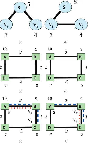
In general, the existing Multicast-aware Virtual Network Embedding (MVNE)
ap-proaches process the node mapping according to the order of the requested computing
re-source and/or path cost. As shown in Fig. 4.1a, there are three virtual nodes in a multicast
VN request where S is the multicast source node, V1 and V2 are the multicast destination
nodes. The requested CPU resource from node S, V1 and V2 are listed along the respective
node. Fig. 4.1c shows the substrate node where the number beside a node indicates the
available CPU resource and the number on the link is the cost of the link resource. Based on
the requested CPU load or link resource/cost as Enhanced Greedy Node Mapping (EGNM)
algorithm in [38], the VN request in Fig. 4.1a will be mapped onto Fig. 4.1c as shown in
Fig. 4.1e. In other words, nodes S, V1 and V2 are mapped to substrate node A, C and B,
respectively. The virtual link S−V1 is mapped to a physical pathA−B −C while S−V2
is mapped to physical path A−B. As a result, when node S sends multicast traffic to nodeV1 and V2, the same multicast traffic goes through pathsA−B−C and A−B of the
substrate network. Clearly, the same multicast traffic travels the physical link A−B twice (or redundantly), which results in network resource wastage. Similarly, the scenario in Fig.
(b-d-f) shows the multicast traffic to node V1 travels from node A to node B, then to node
C. The same multicast traffic (from node V1) to nodeV2 travels fromC toB. The fact that
(a) (b)
(c) (d)
(e) (f)
[image:41.612.124.495.75.677.2]In [39], we propose an efficient Closeness-Centrality based Multicast-aware VNE
(CC-MVNE) algorithm to minimize the resource wastage as indicated in Fig. 4.1, while
maxi-mizing the sharing of substrate nodes and links. The basic idea of the proposed CC-MVNE
algorithm is to reduce the number of used links to access all destinations from source node
by using of the technique of closeness-centrality (CC) [40]. During the mapping process,
CC-MVNE simultaneously maps the nodes and links together while minimizing the needed
resources for the virtual nodes/links and multicast transmission in the network.
4.1 Closeness-Centrality based Multicast Virtual Network Embedding
Intuitively, mapping a virtual node to a substrate node with the most available
com-puting capacity may allow more CPU sharing while selecting the shortest (or least-cost)
substrate path to embed virtual link e will help in reducing the bandwidth consumption of e. However, such greedy approach may result in the resource wastage for the multicast service as shown in Fig. 4.1. In the following, similar to building a multicast tree in IP
net-work, we consider mapping a virtual node to a substrate node that is close to nodes within
the multicast group (i.e., substrate nodes with mapped virtual multicast nodes). We
pro-pose an efficient Closeness-Centrality based Multicast-aware VNE (CC-MVNE) algorithm
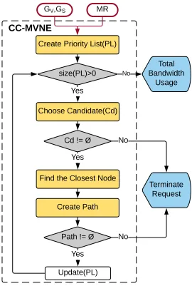
for the aforementioned MVNE problem. Fig. 4.2 and Algorithm 1 show the flowchart and
GV,GS MR
Create Priority List(PL)
Total Bandwidth
Usage
Update(PL)
CC-MVNE
size(PL)>0
Yes Yes
Cd != Ø
Choose Candidate(Cd)
Find the Closest Node
Create Path
Path != Ø
Yes
Terminate Request No
No
No
Figure (4.2) Flowchart of CC-MVNE Algorithm
As shown in Algorithm 1, the inputs of CC-MVNE algorithm are the information of
Substrate Network (SN), Virtual Network (VN) and projected Multicast service Request
[image:43.612.172.442.71.472.2]Algorithm 1 Heuristic CC-MVNE Algorithm
1: procedure CC-MVNE(GV,GS, M R) 2: PL ←P riorityList(GV, M R)
3: MN ← ∅ .holding set of mapped nodes on the SN
4: ML ← ∅ .holding set of mapped links on the SN
5:
6: while size(PL) >0do 7: if size(MN)6= 0 then
8: CdF irst ←Candidate(GS, P L[0])\MN 9: MN ←MN ∪Closeness(CdF irst, N R(MN)) 10: ML←ML∪P ath(MN, GS)
11: PL ←P L\P L[0]
12: else
13: CdF irst ←Candidate(GS, P L[0]) 14: CdSecond ←Candidate(GS, P L[1])
15: MN ←MN ∪Closeness(CdF irst, CdSecond) 16: PL ←P L\P L[0]
17: end if
18: Map CdF irst to the return node of Closeness()
19: Using least-cost path to map the corresponding
20: virtual links connected to CdF irst
21: end while
22: return GS(MN, ML) 23: end procedure
P riorityList() function is getting MS over VN as shown in Algorithm 2. In MS, we have one source node that has the highest priority in all other virtual nodes because we
SN. In the algorithm, after adding source node in priority list as the first node, the function
is sorting all destination nodes in the order of priority by using ofSorting() function defined in Algorithm 3 by using of extended bubble sort [41]. The algorithm 3 is getting the set of
vertices, and returns back the all vertices in the order of priority according to their CPU,
bandwidth, and degree levels. At the beginning, all nodes (vertices) are in descending order
by CPU. If the CPU levels are same for multiple nodes in the list, the function compares
their bandwidth demands on VN. If it is also in same level for multiple nodes, last checking
point is how many connection the virtual nodes in VN have in order to find their priority.
All these three attributes are same for the nodes, then the system handles all nodes in the
same order of node list.
Algorithm 2 PriorityList
1: procedure PriorityList(GV, M R)
2: . M R←< s, D, β >
3: List ← ∅
4: List ←List∪s . s ∈Vv as Virtual Source Node
5: D ←Sortcpu,bw,deg(D) 6: List ←List∪D 7: I ←Sortcpu,bw,deg(I) 8: List ←List∪I 9: return List
Algorithm 3 Sortcpu,bw,deg 1: procedure Sortcpu,bw,deg(V) 2: List ←V
3: n ←size(List)
4: if n ≤1 then return List 5: end if
6: swapped←f alse 7: while !swapped do
8: for i←0 to n−1 do
9: if CPU(List[[i] ¡ CPU(List[i+1] then
10: swap(List[i],List[i+1])
11: swapped ←true
12: else if CPU(List[[i] = CPU(List[i+1] then
13: if BW(list[i] ¡ BW[i+1]then
14: swap(List[i],List[i+1])
15: swapped ←true
16: else if BW(list[i] = BW[i+1] then 17: if Deg(List[i] ¡ Deg(List[i+1]) then
18: swap(List[i],List[i+1])
19: swapped ←true
20: end if
21: end if
22: end if
23: end for
4.1.1 Virtual Node Mapping
Line 3-4 initializes MN and ML to a set of mapped substrate nodes and links, respec-tively. Then, Line 6-21 tries to map all virtual nodes in P L. If MN is not empty, for the next virtual node in P L, theCandidate() function as shown in Algorithm 4 called in Line 8 finds all available candidate substrate nodes. With the candidate set, CC-MVNE finds the
closest node to the neighbors of the virtual nodes that are already mapped with substrate
nodes by using the Closeness() function. As shown in Algorithm 5, the closeness-centrality is computed through Eq. 4.1.
X
u∈NS,V⊂NS\{u}
1/Dijkstra(u, V) (4.1)
Algorithm 4 Find the Candidate Set
1: procedure Candidate(GS,vV) 2: List ← ∅
3: for vsi ∈NS do
4: if CP U(vV)≤CP U(vis) then 5: if BW(vV)≤BW(vis) then 6: List ←List∪vsi
7: end if
8: end if
Algorithm 5 Determine the Closest Node
1: procedure Closeness(V1, V2)
2: min ←M AX IN T 3: saved ←V1[0]
4: for v ∈V1 do
5: total←0
6: for v ∈V2 do
7: total = total + Dijkstra(u, v)
8: end for
9: if min > total then
10: min ← total
11: saved← u
12: else if min = totalthen
13: if deg(saved)< deg(u) then
14: if max(BW(saved))< max(BW(u))then
15: min ←total
16: saved←u
17: end if
18: end if
19: end if
20: end for 21: return saved
22: end procedure
4.1.2 Virtual Link Mapping
[42] while satisfying the requested bandwidth demand. The substrate node with the highest
closeness ratio is then selected to map the current virtual node and the shortest paths are
used to map the corresponding virtual links as shown in Line 18-20 of Algorithm 1. IfMN has no mapped node, the algorithm takes first and second elements ofP L to find the candidate sets.
Algorithm 6 Find the Shortest Path
1: procedure Path(MN,GS) 2: vertex ←MN[size(MN)−1]
3: minDistance ←Dijkstra(MN[0], vertex) 4: saved ←MN[0]
5: for i←1 to size(MN)-2 do
6: cost =Dijkstra(MN[i], vertex) 7: if cost < min k cost = minthen
8: BW1 ←min(BW(Dijkstra(MN[i], vertex))) 9: BW2 ←min(BW(Dijkstra(saved, vertex)))
10: if BW1 >BW2 then
11: min ← cost
12: saved ←MN[i]
13: end if
14: end if
15: end for
16: return Dijkstra(saved, vertex) 17: end procedure
4.1.3 An Example of CC-MVNE
As an example, Fig. 4.3 shows the mapped results of CC-MVNE if the input VN and
SN are the ones in Fig. 4.1a, 4.1b and 4.1c. According to the requested VN in Fig 4.1a,
(a) (b)
Figure (4.3) The mapping result of CC-MVNE
as B and add B in MN. Next, it finds the closest node of the second element in P L, which isA. Then, the algorithm creates a path from B toA. The last node inP Lis mapped onto
C, and CC-MVNE generates a path from B toC. In the end, Fig. 4.1a is mapped as Fig. 4.3a by CC-MVNE. Similarly, the VN request in Fig. 4.1b is mapped as Fig.4.3b, which
does not incur resource wastage for multicast services.
The computing complexity of CC-MVNE depends on the pre-defined functions. TheP L
creation uses BFS and sorting algorithms. BFS has an average time complexity of O(|V|+ |E|) [41] where |V| and |E| are the number of vertices and edges in the graph, respectively.
In CC-MVNE, the functions of Closeness() and P ath() use the Dijkstra’s shortest path algorithm. The computing complexity of Dijkstra’s algorithm for vertex-based cost isO(|E|+ |V|log|V|) [42]. The closeness-centrality algorithm takesO(|V||E|+|V|2log|V|) computing
time [40]. Hence, the CC-MVNE algorithm can take O(|V|2|E|+|V|3log|V|) computing
[image:50.612.124.490.76.270.2]4.1.4 Experimental Results
5 10 15 20 25
0 500 1000 1500 2000 2500 3000
Bandwidth Demand (B)
Total Bandwidth Usage
CC−MVNE EGNM
(a) Bandwidth Usage vsB
10 15 20 25 30
0 500 1000 1500 2000 2500
Computing Demand (CPU)
(b) Bandwidth Usage vsCP U
3 4 5 6 7 8 9 10
0 500 1000 1500 2000 2500
Number of Virtual Nodes (V)
(c) Bandwidth Usage vs V
Figure (4.4) Performance results of bandwidth usage while varying B, CP U and V
We evaluate the proposed CC-MVNE algorithm, and compare it with the Enhanced
Greedy Node and link Mapping (EGNM) algorithm in [38].
In the simulation, we use the random graph generator defined by Erdos-Renyi graph
structure to create the substrate network (SN) and multiple virtual networks (VNs) [37].
We generate the SN graph with 30 nodes that are randomly connected by 90 links. As
[image:51.612.88.527.122.539.2]5 10 15 20 25 0
50 100 150
Bandwidth Demand (B)
Number of Hops
CC−MVNE EGNM
(a) Number of Hops vs B
10 15 20 25 30
0 50 100 150
Computing Demand (CPU)
(b) Number of Hops vsCP U
3 4 5 6 7 8 9 10
0 50 100 150
Number of Virtual Nodes (V)
(c) Number of Hops vs V
Figure (4.5) Performance results of used hops while varying B, CP U and V
[5−CP U] whereCP U denotes the maximum computing resource a substrate node employs. The bandwidth capacity of substrate links is in the range between 5 and B where B is the maximum bandwidth a substrate link has.
A large number of virtual networks with [3−10] VN nodes that have random computing
and bandwidth demands are generated. The computing demands of each virtual node are
[image:52.612.85.523.67.488.2]VN and MS, we vary the requested CP U and B based on different random seeds to obtain the following average results.
Table (4.1) Network Simulation Parameters of CC-MVNE Performance
Substrate Network Virtual Network
Computing Resource [5-40] [10-30]
Bandwidth [5-35] [5-25]
Figs. 4.4a, 4.4b, 4.4c show the total bandwidth usage performance when varying the
virtual link bandwidth, computing demand and number of virtual nodes, respectively. The
performance of the total number of used hops are showed in Fig. 4.5a - 4.5c. In Fig. 4.4a, the
maximum demand of computing resource is 15, and the requested bandwidth, varies from 5
to 25. As one can see that the proposed CC-MVNE outperforms the EGNM algorithm by as
much as 40% when increasingB. This is because the proposed CC-MVNE can effectively use the closeness-centrality technique to map the virtual network with multicast service onto the
substrate network while minimizing the bandwidth wastage(or transmission redundancies)
as identified in Fig. 1. In fact, the advantages of the proposed CC-MVNE lie in two aspects.
First, the proposed CC-MVNE can map the virtual network onto the substrate network
with less bandwidth usage, which is further verified by the smaller number of hops in Fig.
4.5a. Second, the closeness-centrality technique enables the mapping the VN with multicast
services while avoiding the bandwidth wastage(or transmission redundancies) in Fig. 1.
The total bandwidth usage increases with B in Fig. 4.4a while the number of hops for the mapping slightly increases with B as shown in Fig. 4.5a. Similarly, when increasing the requested computing demand and the number of requested virtual nodes, both the total
bandwidth usage and the number of hops for virtual links from the proposed CC-MVNE
increases. This is due to the fact that the increasing requested computing resource, node
and the limited SN resource may force some virtual links to take longer alternative paths
Interestingly, when the computing demand increases to 30 as shown in Figs. 4.4b and
4.5b, the curves from CC-MVNE get very close to (or overlap with) that from EGNM. This
is because when the computing demand of the virtual nodes is large enough, there is very
limited number of physical nodes, which a virtual node can map to. In other words, when
there is not many options to map a virtual node, both CC-MVNE and EGNM essentially
just carry out the link mapping with the shortest paths, resulting in similar performance.
Figs. 4.4c and 4.5c show that increasing the number of virtual nodes will lead to
more consumed bandwidth and longer paths by both CC-MVNE and EGNM. Again, the
proposed CC-MVNE outperforms the EGNM algorithm by a significant margin in terms of
total bandwidth usage and total number of used hops when varying the number of virtual
nodes.
4.2 Chapter Summary
In this chapter, we have introduced the Closeness-Centrality based Multicast-Aware
VNE (CC-MVNE) algorithm that minimizes the resource consumption and maximizes the
sharing of the resource for mapping multicast-oriented virtual network requests. The
pro-posed closeness-centrality technique allows the process of multicast VNE to use less
band-width or short paths to satisfy the virtual network request while avoiding the bandband-width
wastage for multicast services. Our simulation and analysis have shown that the proposed
PART 5
VIRTUAL MULTICAST TREE REQUEST EMBEDDING
When a given virtual request in the form of multicast tree [43], we have investigated
how to efficiently embed virtual multicast trees while minimizing the required resource and
the redundant multicast transmissions in the substrate networks has not been investigated
in the existing works. As an example shown in Fig. 5.1a, virtual node A is the source node of the multicast request. Node B, C and D are the destination nodes receiving multicast streams from nodeA. In this Virtual Multicast Tree (VMT) request, each node also demands a certain CPU resource as shown by the number along the node. Fig. 5.1b is the substrate
network, where the number beside a substrate node indicates the available CPU resource
of the node and the number on a substrate link shows the cost of the substrate link. If we
assume that each substrate link has enough bandwidth and apply traditional VNE or MVNE
schemes (e.g., the one in [11]), we will map the nodes according to the request/available CPU
resource as shown in Fig. 5.1c. Based on the request/available CPU resource, node A, B,
C and D are embedded to substrate node V4, V1, V2 and V3, respectively. The virtual link
A−B, A−C and C−Dare mapped to substrate path V4−V2−V1, V4−V2, and V2−V3
by using of the traditional minimum cost strategy, respectively. Hence, when node A sends multicast traffic in Fig. 5.1a, the multicast data will be transmitted toB andCalong virtual link A−B and A−C, respectively, as shown by the red dash line and blue dot line in Fig. 5.1c. Node C then forwards the same multicast data to D along virtual link C −D, as shown by the brown dotdashed line. Note that, when examining the traces of the multicast
data in the substrate network, the same multicast data travels on the substrate link V4−V2
twice (or redundantly), which leads to the resource wastage or inefficiency in the substrate
(a) (b)
(c)
Figure (5.1) Redundant multicast transmissions for Multicast Tree Embedding
In [43], for the first time, we study how to design efficient algorithms to map a virtual
network (in the form of virtual multicast tree) request onto the substrate network while
minimizing the required resource and multicast transmissions. We define a novel problem,
namely, Virtual Multicast Tree Embedding (VMTE), which is different from traditional
[image:56.612.117.500.67.547.2]map these nodes onto the substrate network for multicast services, which can lead to the
redundant transmission as showed in Fig. 5.1. Similarly, in traditional VNE, one is given
a virtual network graph and the VNE results may not be efficient in handling multicast
traffic, while encountering similar inefficiencies as showed in Fig. 5.1. We note that VMTE
is also different from IP multicast routing, whereas IP multicast routers are fixedly located
and mapping multicast routers (or virtual nodes) is not needed. Accordingly, we propose
an efficient algorithm, called Virtual Multicast Tree Embedding based on dynamic Impact
Factor (VMTE-IF), to minimize the required resource and multicast transmissions. The
proposed VMTE-IF algorithm maps the virtual nodes and links simultaneously to reduce
the resource needed for the multicast traffic from a source to all destinations by using the
Closeness-Centrality (CC) technique [40] with a dynamic local capacity metric (or impact
factor).
5.1 Virtual Multicast Tree Embedding with Dynamic Impact Factor
In this section, we propose the Virtual Multicast Tree Embedding based on dynamic
Impact Factor (VMTE-IF) algorithm to conduct the node and link mapping by using the
technique of Closeness-Centrality (CC) and a proposed dynamic local Impact Factor (IF)
as shown in Algorithm 7. Intuitively, to map a virtual multicast tree, we need to find a
similar tree structure in the substrate network that yields less bandwidth and multicast
transmission redundancy. Hence, the basic idea of VMTE-IF is to embed a virtual node
onto a substrate node that is close to substrate candidates of multicast group members and
map virtual links to the nearby mapped neighbors with minimal resource and redundant
Algorithm 7 Heuristic VMTE-IF Algorithm
1: procedure VMTE-IF(GV, GS, M R)
2: ΛS ← ∅ .hold mapped substrate nodes
3: ΛV ← ∅ . hold mapped virtual nodes
4: χ← ∅ .hold all substrate paths
5: ζ ← ∅ . hold all substrate candidate sets
6: G0S ←P rune(GS, β) 7: for v ∈NV do
8: ςv ←Candidate(G 0 S, v, β) 9: ζ ←ζ+ςv
10: end for
11: while size(ΛV)< size(NV) do 12: η←ImpactF actor(GV,ΛV, ζ, β) 13: µ←Closeness(G0S, η,Ω(η), ζ, β)
14: if µ6=∅ then 15: ΛS ←ΛS∪µ 16: ΛV ←ΛV ∪η
17: else
18: terminate . block the mapping process
19: end if
20: if ΛV ∩Ω(η)6=∅ then
21: P, G0S ←ShortestP ath(G0S,ΛS,ΛV,Ω(η), µ, β) 22: if P 6=∅ then
23: X ←X+P . hold mapped substrate link(s)
24: else
25: terminate . block the mapping process
26: end if
27: end if
28: ζ ←ζ−ΛS 29: end while
30: Hold all links to connect mapped substrate nodes(X)
31: Calculate the cost of link usage with β demand
32: return β∗Σ∀p∈X
χp∗ωp
.∀p∈LS
Finding Substrate Candidates
As shown in Algorithm 7, given a virtual network (in the form of a tree), a shared
substrate network, and multicast tree request (M R) over the virtual network, VMTE-IF algorithm begins with the process of pruning SN to check the available bandwidth of each
substrate links in the SN. In Line 6, the P rune() function removes substrate links that cannot satisfy the bandwidth demand (β) of MR. Line 7-9 finds all substrate candidates that are satisfying the total bandwidth demand of virtual nodes with their neighbors (Ω)
and save them in the set of candidates (ζ) as shown in Algorithm 8. Each virtual node has a set (ςv,∀v ∈NV) of substrate candidate nodes that own enough resource.
Algorithm 8 Find the Candidate Set
1: procedure Candidate(G0S, v, β)
2: List← ∅ . hold all candidate nodes
3: for n ∈NS0 do
4: if c(v)≤c(n) then 5: breq ← |Ω(v)| ∗β 6: bres ←Σ∀m∈Ω(n)b(nm)
7: if breq ≤bres then
8: List←List∪n
9: end if
10: end if