evaluation of design is discussed. A photographic pro-gram is also described, which takes into account both the motorist's view and that of a pedestrian viewing the com-plex interchange from the surrounding area.
•HIGHWAY designers have known for some time that designing and building highways is not only a matter of producing good roads that are adequate for the safety of highway users, but also that they must be attractive and pleasing to the eye. This intrinsic re-quirement has become known as "highway aesthetics," and although it has not yet been precisely defined, it is becoming one of the prerequisites of highway alignment design.
Some successful work has already been done and this has enabled a more critical evaluation of the aesthetics in alignment design. Wider investigation is now being ac-complished by means of computer programming techniques and, in addition to this, the three-dimensional model method is providing a further means of examining designs, particularly of interchanges, so that adjustments can be made during the functional
de-sign stages. This paper discusses some notable achievements in the construction of three-dimensional models and advances other ideas and methods, which it is hoped will assist in the comprehensive evaluation of future highway design.
KNOWN TECHNIQUES FOR THREE-D MODELS
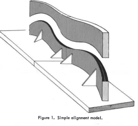
Perhaps the simplest way of constructing a three-dimensional model is the method used in Germany (1) in which a model is constructed by cutting profiles from plain or corrugated cardboard, and mounting them on boards according to the horizontal align-ment. The model roadway itself is constructed of paper strips of the required width. For more impressive representations, the profiles are overstated in the ratio of 1 :10 or 1 :5. For perspective or photographic control, a single scale is used for both plans and profiles. However, more comprehensive models, representing the terrain adjacent to the alignment corridor, incorporate cross sections of the immediate surroundings (Figs. 1 and 2 ).
For models representing larger terrains, contours are cut from a single styrofoam sheet. After placing the sheet on a wooden base, the corresponding contours are then lifted up vertically into the proper elevation and supported by blocks of plastic or other material as shown in Figure 3. The various contour sheets are then glued together and the sharp corners of the sheets are either cut off or filled in with a suitable filler. The
Paper sponsored by Committee on Geometric Highway Design and presented at the 48th Annual Meeting.
Figure 1. Simple alignment model.
roadway is then cut out along the proposed alignment by means of an electrically heated wire.
In the Netherlands a different type of model (2), known as the "Latten model," rang-ing in scale from 1 :40 to 1 :5, has been used. This model is constructed on a special layout table, which usually requires a fair-sized workshop. The roadway profiles are built up by means of wooden or metal supports, spaced about one foot apart, on top of
111111111111111111111111111111111111mij111111111111111111111111111111111111111111ij11111111111111111111111111111IB11111111111111111111111111111111111111m111u111111111111111111111
Figure 3. Terrain model.
which are fixed thin black wooden strips to represent pavements. The completed model shows terrain and landscaping of the immediate area (Fig. 4 ).
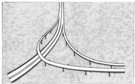
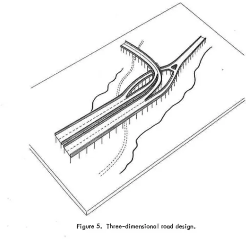
A somewhat different technique has been developed in Great Britain (3) in which the basic unit consists of a three-legged table with a rigid foam plastic sandwich fixed to the top into which steel pins can be pressed by hand. Depending on the lengths and the design, additional tables are set up as required. Plans are then laid out and steel pins
inserted to proper elevations along the centerline. A rubber extension with curvature in both planes is then fitted across the top of the pins, usually to a scale of 1 in. = 15 ft (Fig. 5).
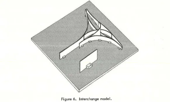
Model building for more complex designs (such as interchanges) has been adopted in some American states (4). In this method the model is built on a base plan of the interchange and pasted onto a rigid plywood sheet. The datum to accommodate the lowest sag is determined and profiles of all roadways are cut from prints and glued onto flexible cardboard. These in turn are placed on corresponding baselines of the plan base by means of balsawood blocks nailed to the plywood sheet. To facilitate better visual evaluation and different profile elements they are color coded according to type; i.e., roadways, ramps, and structures (Fig. 6).
Another method, used in California (5 ), is to build up the terrain with sections of styrofoam that are arranged to conform -with the contour map of the area. This is sanded and covered with putty and painted; finally it is spread with glue and covered with ground wool to show the landscape. Trees made of sponge rubber and buildings copied from aerial photographs or ground photos are added. Grades of roadways are represented by means of wooden blocks; roadways and bridges are cut from pressboard and wooden blocks are used to duplicate prestressed concrete supports (Fig. 7).
Another simple method, which is not too different from those described, has been developed by the Department of Highways, Ontario. It consists of cutting pairs of terrain and slope strips of styrofoam on both sides of the roadway alignment. In this method, styrofoam is cut along the horizontal alignment by means of a thin electrically heated wire. This is followed by a second cutting to represent the profile of the line; side slopes are formed by adjusting the electrical wire to the slope gradients. All are glued together and attached to the layout plan. A thin layer of Pollyfilla is then applied
Figure 6, Interchange model.
and the pavement ribbon, made of thin cardboard, is pasted onto the roadway alignment. The model is then equipped with colored strips of a mosaic plan showing the terrain and land-use pattern. Figures 8 and 9 illustrate the cutting and assembling process.
CASE STUDY
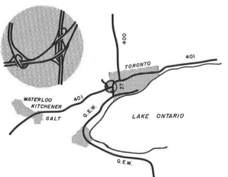
The case study discussed is a new design of an existing interchange at the intersec-tion of Highway 401 (MacDonald-Cartier Freeway) and Highway 27, located in the
Figure 8. Cutting of small terrain model. west section of Metropolitan Toronto in Ontario. The existinglayout of the
inter-change is illustrated in Figure 10, with Highway 401 as the major east-west route, Highway 27 as the north-south route, and the Airport Expressway, to the Interna -tional Airport at Malton, some two miles to the northwest.
Figure 9. Assembly of small terrain model.
Development and land use in the region is mainly residential along Highway 27. From Highway 401 north, the land is first zoned for industrial purposes and further out it is zoned for residential use. Because of industrial growth and other developments, large traffic volumes are anticipated in the area with heavy morning and evening peak-hour loads.
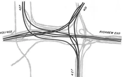
Traffic planning studies in this region have shown the future traffic desires and pat-terns to be as indicated in Figure 11. Based on these projected traffic volumes and patterns, the design finally selected is shown in Figure 12.
Comparing the existing interchange with the selected redesign, the following addi-tions and changes were involved: (a) realignment of Highway 27 to join with the Air-port Expressway; (b) a new freeway, Highway 403, leading southwesterly to link up with the Richview Expressway; and (c) a collector-distributor system for Highway 27.
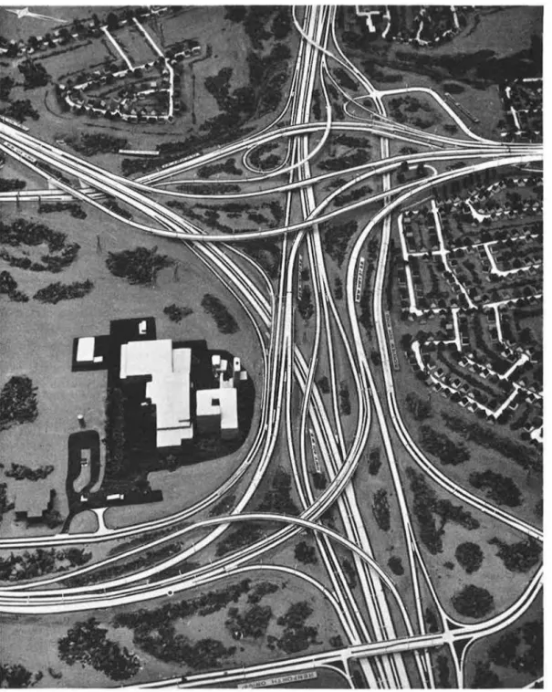
The proposed design of the interchange at this location involves 27 structures with a total deck length of approximately 2½ miles, several retaining walls, and about 32 miles of roadways of all types; it extends over an area of about 1,200 acres (Fig. 13).
0 0 ~ o.F:.w, 401 LAKE ONTARIO
t--C\l
st Figure 11. Future traffic volumes.
METHOD OF CONSTRUCTION OF MODEL FOR THE CASE STUDY The basic building materials for this model were urethane sheets, wooden blocks and thin but firm cardboard sheets, etc. A two-step approach for its construction was necessary to: (a) build up the terrain model of the interchange area and its surround-ings, and (b) construct the design in both planes, and to adjust it to the terrain.
The working scales selected for use on this model were 1 in. = 100 ft for horizontal alignment and 1 in. = 40 ft for vertical alignment; two sets of contour plans including the design layout were utilized.
Construction Steps
The following steps were used in the construction of the model:
1. A print of the contour plan of the area was pasted to a ½-in. -thick urethane sheet, which was attached to a ¾-in. -thick plywood base. Two consective contour lines were
RICHVIEW EXP.
Figure 13. Overall view of new interchange.
traced on each subsequent urethane sheet-one line for the corresponding elevation, and the other to position the next urethane contour sheet. Each sheet was then cut along the contour line starting with the lowest contour so that when stacked up the sheets re-produced the terrain model of the whole area.
2. The interchange design layout was pasted onto a thin sheet of cardboard and the layout design cut out so that it could be used as a template. As each contoured sheet
on a three-dimensional model. The viewer's eyes are too far above the level normally experienced when driving and the resulting view of the model is only from above, or an oblique view as if in a stationary position. This dual disadvantage restricts detection of possible faults or desirable improvements in the design. Therefore, to fully ap-praise the proposed design, a three-phase study of the model by means of motion and still pictures was undertaken.
ApPearance of the Constructed Interchange From the Onlooker's View
In order to consider the constructed interchange from the viewpoint of a pedestrian viewing the area surrounding the interchange, a photographic program was set up along the four roads enclosing the interchange complex.
To obtain a comprehensive overall view, a number of locations were selected on local streets and other points around the interchange from where scanning views could be obtained and still pictures taken. Figure 14 illustrates these selected positions. Motorist's View From the Interchange Roadways
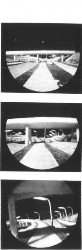
For this purpose a periscope was attached to the movie camera so that the pictures taken were those seen in the horizontal direction a few feet above the road surface.
It is well known that a motorist looks far ahead when driving as well as maintaining an awareness of his immediate surroundings. He controls his vehicle according to im -mediate and later needs and his judgment of the circumstances. Driving within an in-terchange, however, is quite different from open stretches of highway; because of con-fined space greater dexterity is required to cope with merging and diverging traffic. Any design or environmental fe'atures of the interchange that might cause unpleasant
Figure 14. Photographic program for sti 11 pictures {onlooker's view).
·
:.
•·.
·.
_Al .
.ti
/r
.
_
:;.:.:.:.
~
\
_
\
---
~ ·
·
-
\
======
:::c---
·
···\\
MAJOR ROADWAYS - HIGHWAY 401 • • • • • HIGHWAY 427 - • - HIGHWAY 40/-421 - - ff/CHVIE.W EXP'WAY.
.
Figure 15. Photographic program for motion (motorist's view).
reaction on the part of the driver must be avoided. Because of this, unusual design elements and other highway features, such as bridges, structures and retaining walls, and their interrelation with the design and environment, must be carefully examined to avoid any condition that might cause drivers to feel ill at ease or unsafe while nego-tiating the interchange.
The photographic program for a motorist's view is illustrated in Figure 15. It con-tains all the major roadways of the proposed interchanges as represented by the model. View of Construction and Total Environment
The third photographic program in the design investigation was to determine if the interchange, as a whole, would form an integrally aesthetic part of the total environ -ment. This was accomplished by means of oblique motion pictures taken 8 in. above the model surface (Fig. 16). Some examples of views obtained from the photographic program are shown in Figures 17, 18, and 19.
ANALYSIS AND EVALUATION
For the purpose of design analysis and evaluation, the model photographs (still and movie) were shown to a randomly formed group of drivers consisting of six men and four women ranging in age from 20 to 60 years. Their occupations and individual travel patterns were as follows:
Men Drivers Occupation Clerk Engineer Executive Mechanic Truck driver Salesman Traveling Pattern Occasiona I ly Daily Daily Occasionally Daily Daily Women Drivers , Occupation Housewife Clerk Clerk Librarian Traveling Pattern Occasionally Daily Daily Occasionally
Single slides and 200-frame sections of motion pictures were shown to the group and guidance was given on how to rate their impressions. Each member of the group was then requested to answer the following question as the slides and movies were presented: What is your impression of the general appearance of the roadway including environ -ment, etc.? The choice of answers was very good, good or poor.
The three photographic programs (Figs. 17, 18, and 19) were those that incorporated
-~ the criteria for appearance from the onlooker's view, the motorist's reaction as he
drives on various roadways, and finally, how the constructed interchange would form an integral and aesthetically pleasing part of the total environment.
The answers to the questions were then analyzed. Figures 20, 21, and 22 show the results of this investigation; they are regarded as indicators of the quality of the pro-posed design. From these graphs, the following was apparent:
1. A pedestrian's or onlooker's view is generally satisfactory and rated good, ex-cept for the locations 8, 9 and 10. This is understandable because in an otherwise aesthetically pleasing location, the presence of a large brewery, seen from the rear of the buildings, spoils the view.
2. A motorist driving on Highway 401 east- or westbound is generally satisfied with the various design features. There is, however, one location (going towards a sharp curve beyond the structure) over which the driver would be somewhat disconcerted and
- ---· 427
• • • • • • RICHV.EXPW.
Figure 16. Photographic program for motion pictures {view of construction and total
environment).
Figure 17. Onlooker's view.
100-80
••-80 •0-40 "' zi
>- 20 ~ u ffiFigure 19. Environmental check.
VERY GOOD
~ o~- 'l'-~l"-~I"--,~--,,~--,,,---....,.._ .,..._.,.__,,_.__,..
4 6 10
LOCATIONS~
Figure 20. Investigation results, onlooker's view. 100- - - - -(ol VERY 0000
••
7 S - - - - -60 •o-40 0i
e
20 15.
.
... ~~---401 ; : ~:••
10••
16 17..
: SECTIOH~
-
lb)--
---
---
-
-
-
--
-
-
----
-VERY 0000 00~-
--
---
---
-
----
-
-
---60 •o-,o ~ z5
..
20 ~ "..
~ 427 S.B 36..•
..
••
••
40 41 42••
44 SECTION•
7 6•
4•
2 I =- 1,1 --- --- - - -- - ---- -VERY GOOD 00·~-
---
---
---
----401- RICHY. 4 5 6 7 8 RICHY -401 29 28 27 26 25 24•
10 23 II 22!f
SECTIONFigure 21. Investigation results, driver's re-action: (a) Highway 401, eastbound and westbound; (b) Highway 427, southbound and northbound; and (c) Highway 401, Richview
:::
is mainly due to overhead structures, relatively sharp curves, and merging
~ o~~~~~~~~~~~~~
~~~-.-•
4
SECTIONS ~ and diverging of lanes and restricted
sight distances. In the case of Highway 427 northbound, the motorists rated it "good. " The northbound lanes are in an
Figure 22. Investigation results, total environment.
open area with fewer overhead struc -tures and therefore better driving.
3. The oblique pictures taken (1 in. = 40 ft are rated "good" toward the higher limit.
scale) 8 in. above the model surface
CONCLUSIONS
Three-dimensional models are a serviceable tool for the investigation of designs of interchanges with regard to their internal and external appearance.
Photographic, still and motion pictures of the highway model can serve in the detec-tion of possible faults in design and as a means of evaluating the aesthetic appeal of highways and interchanges.
A good deal of work still needs to be done to improve the technique. Doubtless, with time, improvements will be forthcoming that will enable highway engineers to design highways of the future with a built-in aesthetic appeal that would be unattainable without the help of three-dimensional models and photographic programs.
ACKNOWLEDGMENTS
Grateful acknowledgment is made for the assistance of I. C. Campbell and P. J. Harvey, of Planning Branch, Department of Highways, Ontario, for building the model and providing the encouragement to prepare this paper; and to B. Dunstall of the Depart-ment's Photographic Section for filming the photographic programs.
REFERENCES
1. Lorenz, H. Moderne Trassierung. Deutsche Strassen und Briickenbau-Zeitschrift, Heft 9, Sept. 1953, Germany.
2. Bakker, H. B. De belijning van de weg. Wegen, 36e Jaargang, No. 7, July 1962, The Netherlands.
3. Abbott, R. A. Facilitating Three-Dimensional Road Design. Traffic Engineering and Control, Vol. 4, Nov. 1962, Great Britain.
4. Ring, S. L. Highway Interchange Profile Models. Iowa State Highway Commission. 5. Collins, R. M. Design Models-New Techniques Result in Greater Versatility.