®
MAX+PLUS II
Programmable Logic Development
System & Software
January 1998, ver. 8 Data Sheet
Introduction
Ideally, a programmable logic design environment satisfies a large variety of design requirements: it should support devices with differentarchitectures, run on multiple platforms, provide an easy-to-use interface, and offer a broad range of features. Moreover, a design environment should give designers the freedom to use the design entry methods and tools of their choice. The Altera® MAX+PLUS® II development system is a
fully integrated programmable logic design environment that meets all of these requirements.
The MAX+PLUS II design environment offers unmatched flexibility and performance. The rich graphical user interface is complemented by complete and instantly accessible on-line documentation, which makes learning and using the MAX+PLUS II software quick and easy.
The MAX+PLUS II development system includes the following features:
■ Open Interfaces—Altera works closely with EDA manufacturers to
link the MAX+PLUS II software with other industry-standard design entry, synthesis, and verification tools. The interfaces to EDA tools comply with EDIF 2 0 0 and 3 0 0, library of parameterized modules (LPM) 2.1.0, standard delay format (SDF) 1.0 and 2.0, VITAL 95, Verilog HDL, VHDL 1987 and 1993, and other standards. The MAX+PLUS II software interfaces allow designers to create a logic design with Altera or standard EDA design entry tools, compile the design for an Altera device with the MAX+PLUS II Compiler, and perform device- or board-level simulation with Altera or other EDA verification tools. The MAX+PLUS II software currently provides interfaces to tools from Cadence, Exemplar Logic, Mentor Graphics, Synopsys, Synplicity, Viewlogic, and others.
■ Architecture-Independence—The MAX+PLUS II software supports
Altera’s FLEX® 10K, FLEX 8000, FLEX 6000, MAX® 9000, MAX 7000,
MAX 5000, and Classic™ programmable logic device families, and
offers the industry’s only truly architecture-independent programmable logic design environment. The MAX+PLUS II Compiler also provides powerful logic synthesis and minimization to efficiently fit designs with minimal user effort.
■ Multiple Platforms—The MAX+PLUS II software runs on
Windows NT 3.51 or 4.0, Windows 95, or 486- or Pentium-based PCs, and on Sun SPARCstations, HP 9000 Series 700/800, and
IBM RISC System/6000 workstations.
■ Full Integration—The MAX+PLUS II software design entry,
processing, and verification features offer the most fully integrated suite of programmable logic development tools available, allowing faster debugging and shorter development cycles.
■ Modular Tools—Designers can customize their development
environment by choosing from a variety of design entry,
compilation, verification, and device programming options, all of which are described in this data sheet. Additional features can be added as needed, preserving the initial tools investment. Because the MAX+PLUS II software supports multiple device families, designers can add support for new architectures without having to learn new tools.
■ Hardware Description Languages (HDLs)—The MAX+PLUS II software
supports a variety of HDL design entry options, including VHDL, Verilog HDL, and the Altera Hardware Description Language (AHDL).
■ MegaCore™ Functions—MegaCore functions are pre-verified HDL
netlists files for complex system-level functions and are optimized for FLEX 10K, FLEX 8000, FLEX 6000, MAX 9000, and MAX 7000 devices. Created by Altera, MegaCore functions reduce the design task to creating only the custom logic surrounding commonly used system-level functions, which permits designers to focus more time and energy on improving and differentiating the design and final product.
■ OpenCore™ Feature—The MAX+PLUS II software provides the
OpenCore feature, which allows designers to evaluate megafunctions prior to licensing.
MAX+PLUS II Programmable Logic Development System & Software Data Sheet
MAX+PLUS II
Design Process
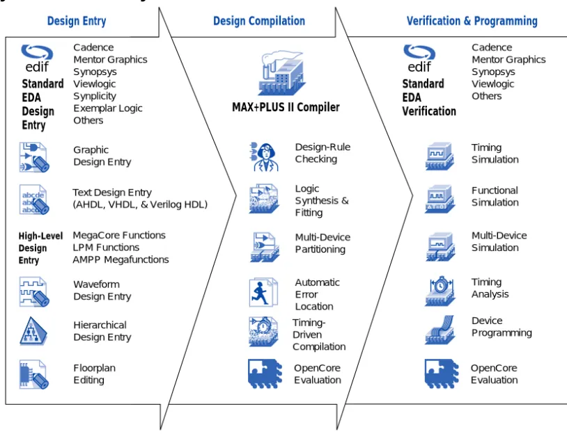
The MAX+PLUS II design process, shown in Figure 1, consists of four phases: design entry, design compilation, design verification, and device programming.
Figure 1. MAX+PLUS II Design Environment
Design Entry
The MAX+PLUS II software can integrate multiple design files—
generated with MAX+PLUS II design entry tools or with a variety of other industry-standard EDA design entry tools—into a single design
hierarchy. The extensive integration between MAX+PLUS II applications allows information to flow freely to and from each application. For example, any errors identified during compilation, simulation, and timing analysis can be automatically located and highlighted in the
Design Entry Design Compilation Verification & Programming
MAX+PLUS II Compiler Cadence Mentor Graphics Synopsys Viewlogic Synplicity Exemplar Logic Others Standard EDA Design Entry Design-Rule Checking Logic Synthesis & Fitting Automatic Error Location Multi-Device Partitioning Timing-Driven Compilation Cadence Mentor Graphics Synopsys Viewlogic Others Timing Simulation Functional Simulation Timing Analysis Device Programming Multi-Device Simulation abc c d ab abcde Waveform Design Entry Graphic Design Entry Hierarchical Design Entry Floorplan Editing OpenCore Evaluation Text Design Entry
(AHDL, VHDL, & Verilog HDL)
MegaCore Functions LPM Functions AMPP Megafunctions Standard EDA Verification High-Level Design Entry OpenCore Evaluation edif edif
MegaCore Functions
Altera MegaCore functions support applications such as peripheral component interconnect (PCI) and other bus interfaces, digital signal processing (DSP), and communications. These functions can be instantiated into designs and simulated with the MAX+PLUS II development system or any Altera-supported EDA tool. For
MAX+PLUS II design flows, the designer simply instantiates the function in the design file. For design files that use third-party EDA tools, designers can instantiate MegaCore functions by specifying the function and port names in the hardware description language (HDL) design file. During design processing, the EDA tool includes the function in an EDIF netlist file. The MAX+PLUS II software compiles the resulting EDIF netlist file for the desired Altera device architecture.
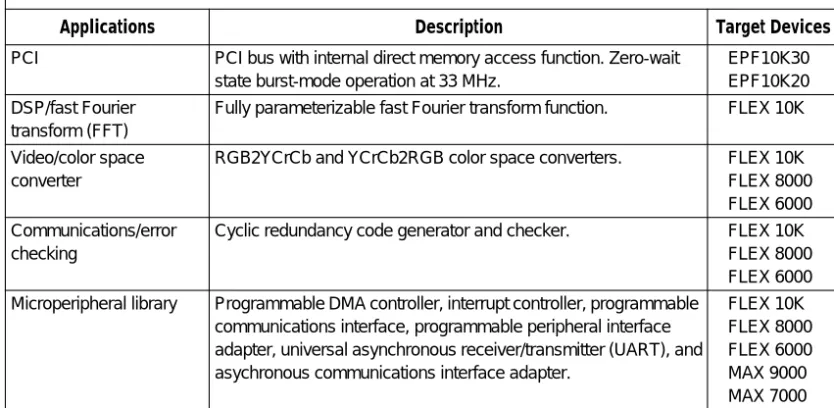
Table 1 describes currently available Altera MegaCore functions.
Altera also provides a wide variety of megafunctions through the Altera Megafunction Partners Program (AMPP). Like Altera, AMPPSM partners
develop megafunctions that are optimized for Altera devices and can also facilitate high-density design. Over 50 AMPP megafunctions that serve a
MegaCoreTM
Table 1. MegaCore Functions
Applications Description Target Devices
PCI PCI bus with internal direct memory access function. Zero-wait state burst-mode operation at 33 MHz.
EPF10K30 EPF10K20 DSP/fast Fourier
transform (FFT)
Fully parameterizable fast Fourier transform function. FLEX 10K
Video/color space converter
RGB2YCrCb and YCrCb2RGB color space converters. FLEX 10K FLEX 8000 FLEX 6000 Communications/error
checking
Cyclic redundancy code generator and checker. FLEX 10K FLEX 8000 FLEX 6000 Microperipheral library Programmable DMA controller, interrupt controller, programmable
communications interface, programmable peripheral interface adapter, universal asynchronous receiver/transmitter (UART), and asychronous communications interface adapter.
FLEX 10K FLEX 8000 FLEX 6000 MAX 9000 MAX 7000
MAX+PLUS II Programmable Logic Development System & Software Data Sheet
OpenCore Feature
MegaCore or AMPP megafunctions can be previewed before licensing via the MAX+PLUS II OpenCore feature. This pre-purchase evaluation system allows designers to instantiate and simulate MegaCore functions or AMPP megafunctions. However, programming files as well as output files for third-party EDA tool simulation can only be generated with an authorization code provided upon licensing.
f
For information of the OpenCore feature, see Introduction to Megafunctions in this data book, or go to MAX+PLUS II Help, or refer to the Altera web site.Industry-Standard LPM Functions
Users can create designs using functions from the industry-standard LPM version 2.1.0. The LPM offers scalable logic functions—such as RAM, counters, adders, and multiplexers—and preserves high-level design information for optimal implementation. The MAX+PLUS II Compiler automatically generates optimized, architecture-specific implementations of LPM functions. LPM functions can be implemented with industry-standard design entry tools, or in schematic or text designs created with the MAX+PLUS II software.
f
For more information on LPM functions, refer to the LPM QuickReference Guide orMAX+PLUS II Help, or go to the Altera web site.
Industry-Standard EDA Design Entry
The MAX+PLUS II Compiler interfaces with industry-standard EDA tools that generate EDIF 2 0 0 and 3 0 0 netlist files, including files that contain LPM functions. The Compiler uses Library Mapping Files (.lmf) to map symbol and pin names from other EDA tools to MAX+PLUS II logic functions. Altera supports the use of LMFs with tools from companies such as Cadence, Mentor Graphics, Viewlogic, and others. VHDL 1987 and 1993 and Verilog HDL design support is also available from Cadence, Exemplar Logic, Mentor Graphics, Synopsys, Synplicity, and others.
f
For more information on other EDA tool vendors, see EDA Software Supportin this data book.OpenCoreTM
edif
LPM
Schematic Capture & Symbol Editing
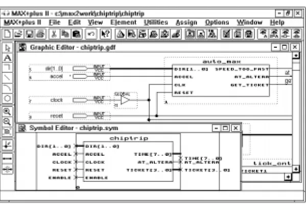
The MAX+PLUS II Graphic Editor, shown in Figure 2, makes schematic design entry fast and easy. The Graphic Editor allows a designer to create and edit a Graphic Design File (.gdf) that includes a combination of megafunctions, macrofunctions, and primitive symbols. The
MAX+PLUS II software provides over 300 74-series, LPM, and custom functions.
The MAX+PLUS II software allows a designer to automatically create a symbol for any design file. With the Symbol Editor (also shown in
Figure 2), the designer can modify a symbol to customize its appearance, or create an entirely new symbol.
Figure 2. MAX+PLUS II Graphic & Symbol Editors
Hardware Description Language (HDL) Entry
The MAX+PLUS II Text Editor is ideal for entering and editing HDL design files written in VHDL 1987 and 1993, Verilog HDL, or AHDL. The MAX+PLUS II Compiler can synthesize logic from any of these languages and map it to any of Altera’s FLEX, MAX, and Classic device families.
MAX+PLUS II Programmable Logic Development System & Software Data Sheet
HDLs can implement state machines, truth tables, conditional logic, Boolean equations, and arithmetic operations—including addition, subtraction, equality and magnitude comparison. The MAX+PLUS II software also supports LPM functions entered in HDLs. Together, these features make it easy to implement complex projects in a concise, high-level description.
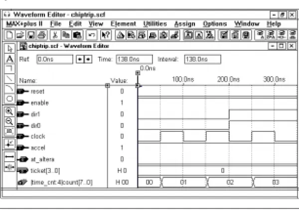
Waveform Design Entry
The MAX+PLUS II Waveform Editor (shown in Figure 3) is used to create and edit waveform design files, as well as input vectors for simulation and functional testing. The Waveform Editor also functions as a logic analyzer that allows the designer to view simulation results.
Figure 3. MAX+PLUS II Waveform Editor
Waveform design entry is best suited for sequential and repeating functions. The Compiler’s advanced waveform synthesis algorithms automatically generate logic from user-defined input and output waveforms that represent registered, combinatorial, and state machine logic. The Compiler automatically assigns state bits and state variables for state machines.
The Waveform Editor allows the designer to copy, cut, paste, repeat, and stretch waveforms; to create design files with internal nodes, flipflops, state machines, and memory words; to combine waveforms into groups that display binary, octal, decimal, or hexadecimal values; to compare two sets of simulation results by superimposing one set of waveforms on another; and to annotate files with comments.
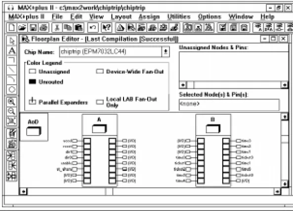
Floorplan Editing
The MAX+PLUS II Floorplan Editor (shown in Figure 4) simplifies the process of assigning logic to device pins and logic cells. A graphical image of each device used in a project allows easy logic placement. Both high-level and detailed device views are available. The designer can assign pins and logic cells before compiling a design, and can view and modify the results after compilation.
Floorplan Editor features allow the designer to view all assigned and unassigned logic in a device. The Floorplan Editor provides a color-coded view of all logic resources in the device, as well as user assignments, fan-in and fan-out information, and architecture-specific features. Any node or pin can be dragged to a new location. Logic can be assigned to specific pins and logic cells, or to more general regions within a device. Assignments can also be made with menu commands in any
MAX+PLUS II application. All assignments are stored in the text-based Assignment & Configuration File (.acf), which can also be edited in the MAX+PLUS II Text Editor.
MAX+PLUS II Programmable Logic Development System & Software Data Sheet
Figure 4. MAX+PLUS II Floorplan Editor
Hierarchical Design Entry
Hierarchical designs can consist of design files created using several different methods, including schematic capture, HDL design entry, waveform design entry, and industry-standard netlist files. The
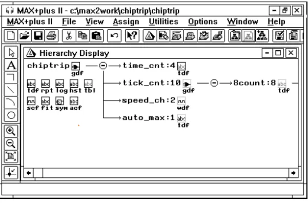
MAX+PLUS II software supports multiple levels of hierarchy in a single design. This flexibility allows designers to use the design entry method best suited to each portion of the design. The MAX+PLUS II Hierarchy Display, which displays the hierarchical structure of a project, allows designers to traverse the hierarchy easily, automatically opening the appropriate editor for each design file. See Figure 5.
Figure 5. MAX+PLUS II Hierarchy Display
Design Compilation
When the MAX+PLUS II software processes a design, the MAX+PLUS II Compiler reads in design files and produces output files for
programming, simulation, and timing analysis. The Message Processor can automatically locate errors detected during compilation and find the source design files for designers. The MAX+PLUS II Compiler can optimize design files for FLEX 10K, FLEX 8000, FLEX 6000, MAX 9000, MAX 7000, MAX 5000, and Classic devices.
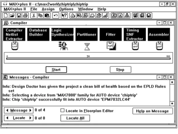
Message Processor
The MAX+PLUS II Message Processor communicates with all
MAX+PLUS II applications, reporting error, information, and warning messages for design problems such as connection and syntax errors, as well as simulation, timing analysis, and programming information. Designers can use the Message Processor to open the design file that contains the source of an error and highlight its location automatically. In addition, the Message Processor can locate errors for the current project in the Floorplan Editor. See Figure 6.
MAX+PLUS II Programmable Logic Development System & Software Data Sheet
Figure 6. MAX+PLUS II Compiler & Message Processor
Logic Synthesis & Fitting
The Logic Synthesizer module in the MAX+PLUS II Compiler supports numerous synthesis options. It selects appropriate logic reduction algorithms to minimize and remove redundant logic, ensuring that the device logic resources are used as efficiently as possible for the target device architecture. It also removes unused logic from the project. Logic synthesis options help the designer guide the outcome of logic synthesis. Altera provides three “ready-made” synthesis styles that specify the settings for multiple logic synthesis options. The designer can choose a default style to set default synthesis options, create custom styles, and specify individual synthesis options on selected logic
functions. Synthesis options can be tailored for a specific device family to take advantage of its architecture. A number of advanced logic options further expand the designer’s ability to control logic synthesis.
The Compiler’s Fitter module applies heuristic rules to select the best possible implementation for the synthesized project in one or more
Timing-Driven Compilation
The Compiler can implement user-specified timing requirements for propagation delays (tPD), clock-to-output delays (tCO), setup times (tSU), and clock frequency (fMAX). Designers can specify timing requirements on selected logic functions and for a project as a whole. The Report File and Compiler messages provide detailed information on how the timing requirements have been implemented in the project.
Design-Rule Checking
The MAX+PLUS II Compiler includes the Design Doctor, a design-rule checker. The Design Doctor checks each design file for logic that may cause system-level reliability problems that are usually discovered only after a design has entered production. The user can choose one of three predefined sets of design rules, or create a custom set of rules.
Design rules are based on reliability guidelines that cover potential design problems such as asynchronous inputs, ripple clocks, multi-level logic on clocks, preset and clear configurations, and race conditions. Rule violations are explained to help the designer determine which edits are needed in the design files.
Multi-Device Partitioning
If a project is too large to fit in a single device, the Compiler’s Partitioner module divides it into multiple devices from the same device family. The Partitioner attempts to split the project into the fewest possible number of devices while minimizing the number of pins used for inter-device communication. The Fitter automatically fits the logic into the specified devices.
Partitioning can be totally automatic, partially user-controlled, or fully user-controlled. If a project is too large to fit into the target device, the designer can specify the type and number of additional devices.
Industry-Standard Simulation Formats
The MAX+PLUS II Compiler can create netlist files for use in a variety of simulation environments. These netlist files contain post-synthesis functional and timing information that can be used with standard design
MAX+PLUS II Programmable Logic Development System & Software Data Sheet
The following interfaces are available:
Interface: MAX+PLUS II Software Support:
EDIF Creates EDIF 2 0 0 and 3 0 0 netlist files that provide functionality and timing for third-party simulators.
Verilog HDL CreatesVerilog HDL netlist files that can be used with Verilog HDL simulators.
VHDL Creates VHDL 1987 and 1993 netlist files that can be used with VHDL simulators.
For each interface, the Compiler can optionally generate a version 1.0 or 2.1 Standard Delay Output Format File (.sdo) that includes timing information for simulators that require timing and functional information in separate files.
Programming File Generation
Both the MAX+PLUS II Compiler and Programmer can generate
programming files. The following programming file formats are available in the MAX+PLUS II software:
■ Programmer Object File (.pof)
■ FLEX Chain File (.fcf)
■ SRAM Object File (.sof)
■ JEDEC File (.jed)
■ JTAG Chain File (.jcf)
■ Hexadecimal (Intel-format) File (.hex)
■ Tabular Text File (.ttf)
■ Raw Binary File (.rbf)
■ Serial Bitstream File (.sbf)
■ Serial Vector Format (.svf) files
■ Jam™ File (.jam)
f
For more information on programming and configuring devices with these file formats, go to MAX+PLUS II Help.Design Verification
The MAX+PLUS II software offers design verification capabilities— including design simulation and timing analysis—that test the logical
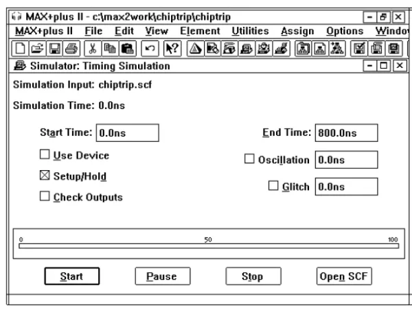
Figure 7. MAX+PLUS II Simulator
The designer either defines input stimuli with a straightforward vector input language or draws waveforms directly with the MAX+PLUS II Waveform Editor. Simulation results can be viewed in the Waveform Editor or Text Editor and printed as waveform or text files.
The designer specifies commands either interactively or in a text-based command file to perform a variety of tasks, such as monitoring the project for glitches, oscillation, and register setup and hold time violations; halting the simulation when user-defined conditions are met; forcing flipflops high or low; performing functional testing; and defining the initial memory content of RAM or ROM blocks. If a setup or hold time,
MAX+PLUS II Programmable Logic Development System & Software Data Sheet
For easy comparison, the designer can superimpose the results of two simulations in the Waveform Editor.
Functional Simulation
The MAX+PLUS II Simulator supports functional simulation to test the logical operation of a project before it is synthesized, thereby allowing the designer to quickly identify and correct logical errors. The MAX+PLUS II Waveform Editor displays the results of functional simulation and provides easy access to all nodes in the project, including combinatorial functions.
Timing Simulation
In a timing simulation, the MAX+PLUS II Simulator tests the project after it has been fully synthesized and optimized. Timing simulation is performed at 0.1-ns resolution.
Multi-Device Simulation
The MAX+PLUS II software can combine the timing and/or functional information from multiple Altera devices, allowing the designer to simulate several devices operating together. Devices from different Altera device families can be used in the same project.
Timing Analysis
The MAX+PLUS II Timing Analyzer can calculate a matrix of point-to-point device delays, determine setup and hold time requirements at device pins, and calculate maximum clock frequency.
MAX+PLUS II design entry tools are integrated with the Timing Analyzer, allowing the designer to simply tag start and end points in the design files or the Floorplan Editor to determine the shortest and longest propagation delays. In addition, the Message Processor can locate and display critical paths identified by the Timing Analyzer in the source design files or in the Floorplan Editor. See Figure 8.
Device Programming
The MAX+PLUS II Programmer, shown in Figure 9, uses programming files to program Altera devices. The Programmer allows the designer to program, verify, examine, blank-check, and functionally test devices. Altera provides all hardware and software necessary for programming and verifying devices, including a Logic Programmer Card, Master Programming Unit (MPU), and programming adapters. The add-on Logic Programmer card (for PCs or compatible computers) drives the MPU. The MPU performs continuity checking to ensure adequate electrical contact between the programming adapter and the device. With the appropriate programming adapter, the MPU also supports functional testing, so that vectors created for simulation can be applied to a programmed device to verify its functionality.
MAX+PLUS II Programmable Logic Development System & Software Data Sheet
Figure 9. MAX+PLUS II Programmer
Altera also provides the ByteBlaster™parallel port download cable, and
the BitBlaster™ serial download cable for device programming and
configuration. The ByteBlaster download cable connects to a DC parallel port and the BitBlaster download cable connects to a standard PC or UNIX workstation RS-232 port to provide configuration/programming data. With the BitBlaster or ByteBlaster download cables, designers can also configure or program multiple devices using the multi-device JTAG chain mode in the MAX+PLUS II Programmer.
f
For more information on the BitBlaster and ByteBlaster download cables, Altera programming hardware and software, other programming hardware manufacturers, and JTAG chain programming and configuration, refer to the following sources:■ ByteBlaster Parallel Port Download Cable Data Sheet in this data book ■ BitBlaster Serial Download Cable Data Sheet in this data book ■ Altera Programming Hardware Data Sheet in this data book ■ Programming Hardware Manufacturers in this data book
command, or pop-up message. Typing Shift+F1 or choosing the context-sensitive help button on the toolbar turns the mouse pointer into a question mark pointer that allows the designer to click on any item on the screen—including logic function symbols or names and text file
keywords—for context-sensitive help on that item.
Software
Maintenance
The Altera software maintenance program ensures that designers will receive the latest version of the MAX+PLUS II development software every quarter. The software maintenance program provides the following benefits:
■ New Device Support—Altera offers devices with the highest density
and performance in the industry. Altera continues to offer additional devices by providing additional devices and package options, which allows designers to create systems with the most advanced devices and packages.
■ New Software Features—New software features and enhancements
make the MAX+PLUS II software easier to use and improve design compilation times. Designers with maintenance agreements receive new features with each MAX+PLUS II upgrade, ranging from HDL synthesis to improved timing-driven compilation.
■ Programming Methods—MAX+PLUS II supports the latest
programming methods, (e.g., system programmability (ISP), in-circuit reconfigurability (ICR), and the Jam programming and test language. Altera continues to enhance its programming hardware and software to make these programming methods easily accessible.
■ Third-Party EDA Interfaces—The MAX+PLUS II software provides
interfaces to all major EDA design tools as a standard feature. These interfaces allow designers to work in the most familiar design environment and implement designs in any Altera device family. Altera continually enhances the MAX+PLUS II design environment
MAX+PLUS II Programmable Logic Development System & Software Data Sheet
Recommended
System
Configurations
To run the MAX+PLUS II software with optimum results, Altera recommends the following system configurations:
PC System Configuration
■ 200-MHz Pentium-based or better PC ■ Available memory as shown in Table 2
■ Microsoft Windows NT version 3.51 or higher, or Windows 95 ■ Microsoft Windows-compatible graphics card and 17-inch color
monitor
■ CD-ROM drive
■ Microsoft Windows-compatible 2-button mouse ■ Full-length 8-bit slot for the programmer card ■ Parallel port (i.e., LPT port)
■ RS-232 serial port for the BitBlaster download cable
Sun Ultra 2 SPARCstation System Configuration
■ Sun Ultra 2 SPARCstation with color monitor■ Available memory as shown in Table 2 ■ Sun OpenWindows 3.0 or higher ■ Solaris 2.5 or higher
■ ISO 9660-compatible CD-ROM drive
■ RS-232 serial port for the BitBlaster download cable
HP 9000 Series 700/800 Workstation System Configuration
■ HP 9000 Series 700/800 workstation with color monitor ■ Available memory as shown in Table 2■ HP-UX version 10.20 or higher ■ HP-VUE
Table 2. Memory Requirements for MAX+PLUS II Systems
Device Family Available Memory (Mbytes) Physical RAM (Mbytes)
FLEX 10K 256 128
FLEX 8000 64 32
FLEX 6000 64 32
MAX 9000 64 32
requirements, refer to the MAX+PLUS II read.me file.
Software
Package
Options
Altera offers a variety of tool configurations and add-on migration products for PC- and UNIX-workstation-based versions of the
MAX+PLUS II software. For more information, go to the Altera web site at http://www.altera.com.
For up-to-date information on MAX+PLUS II software packages and development systems, contact your local sales representative or go to the Altera web site.
Copyright © 1995, 1996, 1997, 1998 Altera Corporation, 101 Innovation Drive, San Jose, CA 95134, USA, all rights reserved.
By accessing this information, you agree to be bound by the terms of Altera’s Legal Notice.