CHAPTER 12
BriSCA FORMULA TWO
2014 TECHNICAL CAR SPECIFICATION RULES
Definitions used in these RulesRHS Rectangular Hollow Section SHS Square Hollow Section CHS Circular Hollow Section
OHS Oval Hollow Section
Axle A solid axle with a wheel at each end (e.g. a front beam axle, or English rear axle), or both sides of an independent suspension arrangement taken as a pair (e.g. a wishbone/bottom arm front suspension design).
Car centre-line The main centre-line of the car is defined as a line running along the horizontal length of the car, equidistant between the two main chassis rails when viewed from above. Engine centre-line The centre-line of the engine is defined as the rotational
centre-line of the crankshaft, measured at the pulley securing bolt.
Standard Type/Size Component of a size, weight and material as originally manufactured. Details can normally be found in the appropriate Haynes manual.
Production Type/Size Component of a size, weight and material as originally manufactured. Details can normally be found in the appropriate Haynes manual.
Original Type/Size Component of a size, weight and material as originally manufactured. Details can normally be found in the appropriate Haynes manual.
TDC Top Dead Centre
ECU Electronic Control Unit General Notes
• It is the driver’s responsibility to present a legal car at all times (including scrutineering, practise, and racing). This is stressed especially for such simple checks as front wishbone lengths, bumper heights, track width, and rear axle alignment.
• The presentation of a car for scrutineering is a declaration by the driver that the car is eligible to race, and complies with all technical and safety rules.
• Any necessary rule changes during the course of a season (most likely to be safety related) will be notified to drivers through the official BriSCA F2 website (briscaf2.com) and the BriSCA F2 newsletter (sent to all registered drivers). Change advisories received from any other source should be checked against these two official sources for authenticity and accuracy.
200
General Technical Rules200.1
The drilling, lightening or other modification of any plates, bars or safety components is NOT permitted unless explicitly stated in these rules.200.2
Standard parts must NOT be changed or altered unless explicit permissionis given in these rules.
200.3
The use of ceramic bearings is NOT permitted anywhere on the car.200.4
Unless a rule explicitly states an action can be taken, a modificationmade, or a replacement part sourced/manufactured, then such actions/ modifications/replacements are NOT permitted. This is the overriding principle for ALL technical rules.
200.5
Unless these published rules explicitly state something can be implemented, then it CANNOT.200.6
Prior approval MUST be sought and received for any changes to the current published rules or to allow the use of any non-standard or modified parts. Requests MUST be submitted to BriSCA F2 and will be considered for the following year’s rulebook. Such parts or changes must NOT be implemented until approval has been granted as appropriate.201
BriSCA Formula 2 Stock Car Definition201.1
A BriSCA Formula Two Stock Car (subsequently referred to as the car) MUST be:• Open-wheel in design and construction around a steel space-frame chassis
• Front-engined • Rear-wheel drive • A single seater car
201.2
The main centreline of the car is defined as a line running along the horizontal length of the car, equidistant between the two main chassis rails when viewed from above.201.3
The engine, gearbox, and driver’s seat, MUST all be fitted along the main centreline of the car within the tolerances quoted in the individual rules below.201.4
The front and rear axles MUST be fitted centrally in the car, relative to the car’s centreline, within the tolerances quoted in the individual rules below.202
Weight and Ballast202.1
Weight202.1.1
The MINIMUM permissible total weight of the car is 650Kg.202.1.2
The MAXIMUM permissible total weight of the car is 715Kg.202.1.3
The MAXIMUM permissible inside (left side) weight distribution is 52.50%.202.1.4
Cars may be weighed at ANY time before, during, or after a meetingand MUST comply with the weight rules at ALL times.
202.1.5
ALL weighing measurements are taken WITHOUT the driver in the car.202.1.6
At ALL tracks, the adding of fluids, or making of changes of any kindto the car to bring it within limits for a post-race weight check is NOT permitted.
202.1.7
At shale tracks ONLY, excess shale may be removed from the car under supervision, and the car subsequently re-weighed if it is found to be outside the legal limits on first weighing after a race.202.1.8
Cars may be modified in order to pass any pre-meeting weight checks WITHOUT penalty.202.1.9
The penalties for inside (left-side) weight infringements are detailed in a separate section of the rulebook.202.2
Ballast202.2.1
Bolt-on ballast is NOT permitted.202.2.2
No solid steel bar or plate may be used over 6mm in thickness in the construction of the chassis, bumpers or nerf-rails that may be construed as ballast.202.2.3
The lamination of steel plates in the construction of the nerf-rail or fuel tank/battery protection, which can be construed as ballast, is NOT permitted.202.2.4
Tubular bars or box section must NOT be filled with ANYTHING that will increase their weight.203
Chassis Construction203.1
General203.1.1
The car MUST have a steel chassis and roll-cage of welded construction.203.1.2
Brazing is NOT permitted on the chassis or roll-cage.203.1.3
The chassis floor, main rails, bumpers, nerf-rails, and roof-plate MUST ALL be in the same horizontal plane when the chassis is placed on a level surface and viewed from the front and rear.203.2
Main Chassis203.2.1
The main chassis rails MUST be constructed of RHS or SHS with a MINIMUM wall thickness of 3mm.203.2.2
The main chassis rails MUST be at least a MINIMUM size of 40mm x 40mm, and at most a MAXIMUM size of 70mm x 70mm.203.2.3
The entire length of the main chassis rails MUST be above the centreline of the wheels when viewed from the side.203.2.4
The main chassis rail vertical centreline, when viewed from the side, MUST pass directly through or above the vertical centres of the front and rear bumpers.203.2.5
The distance between the main chassis rails and the undercarriage MUST be equal on BOTH sides of the car.203.2.6
The main chassis rails MUST be joined to each other at the rear with a transverse cross-member. This cross-member will form one of the sides to which the rear-plate MUST be welded (see below). The joints of the cross-member to the main chassis rails MUST be fully welded.203.3
Roll-Cage203.3.1
The car MUST have an integral 6-pillar roll-cage, welded to the main chassis rails, to protect the driver.either (i) front to back along the line of the main chassis rails, or (ii) side to side between the two chassis rails, thus forming 4 of the 6 required pillars.
203.3.3
The main roll-cage hoops MUST be connected together at the top by two bars: one front and one rear in the case of front-to-back main hoops, one at each side in the case of side-to-side main hoops.203.3.4
Two additional pillars (pillars 5 & 6) MUST also connect the mainchassis rails to the roll hoop(s) above the driver’s head (one pillar on each side of the car).
203.3.5
The main hoops (pillars 1-4), their connecting bars (rule 203.3.3), and additional pillars (5&6) MUST be constructed of SHS or CHS with a MINIMUM wall thickness of 3mm.203.3.6
The main hoops (pillars 1-4), their connecting bars (rule 203.3.3), and additional pillars (5&6) MUST be at least a MINIMUM size of 30mm x 30mm (SHS), or 30mm diameter (CHS).203.3.7
With the exception of the main roll-cage pillars and bars as specified above, all other parts of the roll-cage specified below MUST be constructed of SHS or CHS with a MINIMUM wall thickness of 2.5mm, and at least a MINIMUM size of 25mm x 25mm (SHS) or 25mm diameter (CHS).203.3.8
The top and bottom sections of the middle pillars must NOT be offset from each other where they intersect any side or other protection bars.203.3.9
Side-bars running longitudinally between the front and rear roll-cage pillars MUST be installed on both sides of the car at approximately elbow height.203.3.10
The side-bars MUST abut, or be abutted by, the middle roll-cage pillars on each side of the car, and all joints to the roll-cage pillars MUST be fully welded.203.3.11
The side-bars MUST be equal heights from the chassis rails on both sides of the car.203.3.12
The side-bars MUST measure a MINIMUM of 750mm apart from inside edge to inside edge at the driver’s seat.203.3.13
At least two separate down-bars MUST be installed on each side of the car within the area bordered by the front and middle roll-cage pillars, the main chassis rail and the side-bar, primarily designed to provide protection for the driver from intrusion in to the cab area from bumpers (through the side panel). At least 1 down-bar MUST connect the side-bar to the main chassis rail, whilst a second down-bar MUST connect either the side-bar or the front roll-cage pillar to the main chassis rail.203.3.14
The down-bars MUST be welded at both ends (to the chassis rails and side-bars/roll-cage pillars), and be equally spaced (as far as practically possible, and with the safety of the driver in mind) so as to divide the area (between the front and middle roll-cage pillars, main chassis rails, and side-bars) in to equal size apertures.203.3.15
The use of non-vertical down-bars is permitted to allow triangulation for improved strength, subject to the rules above.203.3.16
The middle roll-cage pillar on each side of the car does NOT count as one of the two down-bars, which MUST be in addition to the 3 roll-cage pillars mandated on each side of the car.203.3.17
The rear roll-cage pillar on both sides of the chassis MUST be joined to the other by a transverse horizontal member. This cross-member will form one of the sides to which the rear plate MUST be welded (see below).203.3.18
The joints of the rear cross-member to the roll-cage pillars MUST be fully welded.203.4
Roll-Cage Plating203.4.1
A steel sheet plate of MINIMUM 3mm thickness MUST be welded to the top of the roll-cage along the full length of all 4 sides (the two main roll-cage hoops and the two connecting bars) to form a protective roof over the driver’s head.203.4.2
The roof plate MUST measure at least a MINIMUM of 560mm in length across its entire width, and at least a MINIMUM of 400mm in width along the mandated MINIMUM 560mm length. These dimensions include the diameter of the roll-cage tube to which the plate is welded, and will therefore be measured from two verticals butting against the outside of the roll-cage tube.203.4.3
The use of a non-rectangular roof plate is permitted, if so designed, but it must conform to the above specification, i.e. be a MINIMUM of 560mm in length at all points, not just the centre, and a MINIMUM of 400mm in width for the minimum 560mm mandated length.203.4.4
A car built/raced to the previous roof-plate dimension specifications (prior to the 2013 rule-book) is permitted a MAXIMUM 2-year run out period (until 31st December 2015), during which time any required changes to the roof plate MUST be made. In such cases the car MUST conform to ALL three of the following specifications to be permitted to race in 2014:• The roof plate MUST measure at least a MINIMUM of 400mm in length across its entire width.
• The roof plate MUST measure at least a MINIMUM of 400mm in width along the mandated MINIMUM 400mm length.
• The roof plate MUST cover a surface area of at least a MINIMUM of 2,240cm sq (to maintain weight and coverage parity with a 560mm x 400mm plate).
203.4.5
ALL new cars MUST conform to the MINIMUM 560mm x 400mm dimensions specified in rules 203.4.2 / 203.4.3203.4.6
From 2016, ALL cars MUST conform to the MINIMUM 560mm x 400mm dimensions specified in rules 203.4.2 / 203.4.3203.4.7
The roof plate must NOT be drilled or lightened in any way, except for the fitting of a roof fin or superstar lights.and the roof plate, such that the helmet cannot strike the roof when the driver is strapped in the racing position.
203.4.9
The rear of the roll-cage MUST be panelled with a steel sheet plate of at least 2mm MINIMUM thickness, and to a MINIMUM height of at least 300mm above the level of the main chassis rails.203.4.10
The rear plate MUST be welded on all sides (to the two roll-cage pillars, a chassis cross-member, and a roll-cage cross-member).203.4.11
The rear plate must NOT be drilled or lightened in any way.203.4.12
It is strongly recommended that the nearside (left) of the roll-cage(between the main chassis rail and the horizontal side-bar) is also panelled with 2mm thick steel sheet plate, welded on all sides, as per the rear of the roll-cage.
203.5
Bodywork203.5.1
ALL panels/body-work, where fitted, MUST be constructed of metal, unless specified below. The use of fibreglass, carbon-fibre, Kevlar, or other materials is NOT permitted.203.5.2
The roll-cage MUST be enclosed with metal panel-work, up to the level of the side-bars, on both sides of the car, and the rear.203.5.3
The area between the middle and rear roll-cage pillars, above the side-bar may be panelled if so desired, but MUST be metal if fitted.203.5.4
Equal apertures MUST be left on BOTH sides of the roll-cage for driver entry/exit.203.5.5
A rear “window” MUST be left open to allow access for scrutineering checks.203.5.6
The engine bonnet/cover is defined as the primary removable section of body-work/panelling enclosing the top of the engine.203.5.7
The engine bonnet/cover MUST be constructed of a MINIMUM of 51% metal by external surface area. It MUST fully enclose the engine compartment, and be securely fitted. The use of non-metal composite material sections, e.g. a rocker-cover bulge, within the construction of the bonnet/cover is permitted, subject to the overall 51% metal rule of the entire removable section.203.6
Windscreen203.6.1
The windscreen aperture(s) must be covered with a steel mesh to protect the driver from projectiles.203.6.2
The steel mesh MUST be no more than a MAXIMUM 40mm matrix, and MUST be a MINIMUM 2.4mm thickness.203.6.3
The steel mesh MUST be securely fitted to the car.203.6.4
It is NOT permitted to drill holes in ANY roll-cage tube/bar for the purpose of mounting the steel mesh.203.6.5
An additional solid screen may be fitted if required (e.g. for racing in the rain or on shale), but it MUST be made of a material that will not shatter if impacted.203.6.6
The steering wheel MUST be positioned well inside the cab, such that the driver’s fingers are not at risk of catching in the windscreen mesh under normal racing conditions.204
Bumpers204.1
The car MUST be fitted with front and rear bumpers constructed of steel.204.2
Both bumpers MUST be constructed with a flat face surface 100mm (4in)deep.
204.3
The MAXIMUM permitted bumper thickness is 30mm (13/ 16in).204.4
The MAXIMUM permitted bumper width is 1676mm (66in). The bumper width is defined as the bumper face, whether flat or angled towards the wheels, and includes any additional bumper hoop ironwork that can be construed as forming part of the face.204.5
Wheel-guard mount plates on the rear bumper may extend beyond the 1676mm (66in) MAXIMUM width; however they MUST be constructed so as to only protrude forward from the rear bumper and NOT create any additional face area to that permitted above.204.6
Bumpers are NOT permitted to protrude beyond the outside edge of the nerf-rails on either side of the car.204.7
Front AND rear bumpers MUST measure 410mm from the ground to the vertical centre of the bumper face, mid-way between the main chassis rails WITHOUT THE DRIVER in the car. This measurement MUST be within a tolerance of +/-10mm, i.e. up to a MAXIMUM of 10mm above or below the stated height.204.8
Bumpers MUST be smooth on ALL extremities.204.9
The front bumper MUST be 250mm or LESS from the front tyres in the horizontal plane.204.10
The rear bumper MUST be 300mm or LESS from the rear tyres in the horizontal plane.204.11
Bolt-on bumpers MUST have a MINIMUM of TWO secondary fixings to prevent the bumper leaving the car should the mounting bolts break in an impact. Each secondary fixing MUST comprise of a steel chain made of MINIMUM 8mm thick diameter links, with ends joined together by a MINIMUM 8mm thick diameter steel shackle encompassing a threaded securing mechanism. The use of nuts, bolts and washers to join the ends of the chain is NOT permitted. Each secondary fixing chain MUST be wrapped around BOTH the chassis and suitable section of the bumper.204.12
The front bumper MUST be fitted with a central lower hoop to helpprevent the car riding up over other cars. This hoop MUST have a horizontal centre section a MINIMUM of 304mm (12in) wide, and be a MINIMUM of 152mm (6in) deep from the underside of the bumper along the entire horizontal section length. This hoop MUST be braced by 2 rear diagonal support struts.
204.13
The front bumper MUST be fitted with a fence-side lower hoop to help prevent intrusion of the bumper end in to another car’s driver’s compartment. This hoop MUST be a MINIMUM of 102mm (4in) deep from the underside of the bumper, smooth on all edges, and the bottom of any tube MUST be capped. Sharp angles, or tapers, of less than 90 degrees that may cause tyre damage are NOT permitted on the bottom of the hoop.DIAGRAM 01
204.14
The front bumper MUST be fitted with a fence-side upper hoop to help prevent intrusion of the bumper end in to another car’s driver’s compartment, and reduce the risk of entanglement with post and rope fences. This hoop MUST be a MINIMUM of 152mm (6in) and a MAXIMUM of 304mm (12in) high from the top side of the bumper, and smooth on all edges.204.15
ALL bumper hoops MUST be made from steel with a MINIMUM 2.5mm wall thickness, and a MINIMUM size of 25mm diameter or square.204.16
All bumper hoops are illustrated in Technical Diagram 01.205
Nerf-Rails205.1
Nerf-rails MUST be fitted to BOTH sides of the car and made of steel.205.2
Nerf-rails MUST be the same height, from the ground, as the bumpers.205.3
The nerf-rails MUST be symmetrical in appearance on BOTH sides of thecar when viewed from above.
205.4
The outer edge of the nerf rail is defined as the outer-most section running between the front and rear wheels, parallel (or just off parallel) to the main chassis rail.205.5
The outer edge of the nerf rail MUST be at least a MINIMUM size of 25mm diameter/square SHS, RHS, CHS or OHS, and MUST be at least a MINIMUM wall thickness of 2.5mm.205.6
The outer edge of the nerf rail MUST be connected to the main chassis rail by a MINIMUM of two support struts, each being at least a MINIMUM material size of 25mm diameter/square SHS, RHS, CHS or OHS.205.7
Mandated support struts, additional support struts, and bracing struts, MUST be steel, but may be of a thinner material than the mandated outer edge of the nerf rail.205.8
Nerf-rails MUST be at least a MINIMUM depth of 100mm from the rear-most point of the outer edge of the rail forwards for a MINIMUM length of 500mm. This measurement does NOT include any angled section joiningthe lower section of the rail to the outer edge of the main nerf rail. This rule is illustrated in Technical Diagram 02.
DIAGRAM 02
205.9
The mandated minimum 100mm depth section of the outer edge of the nerf rail MUST be steel, and MUST be at least a MINIMUM size of 25mm diameter/square SHS, RHS, CHS or OHS, OR steel plate with a MINIMUM thickness of 2mm. The lower edge of any plate used to meet the specified dimensions MUST be welded to support bracing, which may include a lower rail to form a side-pod.205.10
Nerf-rails must NOT extend past the wheels (when the car is fitted with normal dry running wheels) by more than 2in (50mm). This gives a MAXIMUM total chassis width (excluding wheel guards) of 72in (1828mm) if the MAXIMUM permitted track width is used.206
Wheel Guards206.1
A steel wheel guard MUST be fitted around the offside (right) rear wheel, from the rear bumper to the nerf-rail.206.2
The wheel guard MUST be similar in dimensions to the Transit or Escort rear leaf spring.206.3
The wheel guard MUST be bolted to its mounts at BOTH ends using high-tensile nuts and bolts of a MINIMUM 10mm diameter. A guide to fitment is illustrated in Technical Diagram 03.206.4
The use of a wheel guard on the nearside (left) rear wheel is optional, but if fitted it MUST conform to the above rules.207
Engine Firewall207.1
A complete firewall MUST be installed between the engine and the driver’s compartment to help protect the driver from the possibility of burns from fire, fuel, oil or water.207.2
The firewall MUST be made of metal.207.3
The firewall MUST be complete except for minimal sized holes through which essential cables, pipes or the steering column are required to pass.208
Cab Floor208.1
A solid floor MUST be installed in the driver’s compartment (cab).208.2
Where any part of the floor of the driver’s compartment is below theDIAGRAM 03
cab floor MUST be constructed of 3mm MINIMUM thickness steel plate. Aluminium is NOT permitted in this case.
208.3
Where the entire floor of the driver’s compartment is above the bottom of the main chassis rails AND a full under chassis is present (i.e. lower rails extending to at least level with the front transverse edge of the driver’s seat not including any leg side-supports/bracing), the cab floor MUST be constructed of either 3mm MINIMUM thickness aluminium plate (including chequered plate) or 3mm MINIMUM thickness steel plate.208.4
The cab floor MUST extend rearwards from the engine bulkhead firewallfor a MINIMUM distance of 600mm over its entire width.
208.5
The cab floor MUST extend rearwards BEYOND the point at which it overlaps in a vertical plane (across the entire width of the car) with the transverse front edge of the driver’s seat (behind the driver’s knees, not including any leg side-supports/bracing).208.6
The cab floor MUST cover the full width of the area between the chassis rails along the floor’s entire length.208.7
The cab floor MUST be either welded to the chassis, or attached using a MINIMUM of eight (in number) high tensile 8mm nuts and bolts.208.8
Cutting of the cab floor around the bell-housing and gearbox for fitment is permitted. NO other drilling or lightening is allowed.208.9
The front edge of the cab floor may be angled upwards to prevent catching on high kerbs or other obstacles should car design require this.209
Foot Protection Plating209.1
Where ANY part of the driver’s legs or feet are located below the bottom of the main (top) chassis rail a vertical side protection plate of 3mm MINIMUM thickness steel MUST be welded between the main (top) andlower chassis rails to cover the entire side area of the driver foot-well on both sides of the car.
209.2
Where a driver’s legs and feet are located entirely above the bottom of the main (top) chassis rails a vertical side protection plate of 2mm MINIMUM thickness steel MUST be welded between the main (top) chassis rail and the level of the main cab window side-bars to cover the entire side-area of the driver’s legs/feet position.209.3
Where a driver’s feet are located such that they are both above and below the main (top) chassis rails then steel vertical side protection plates MUST be mounted BOTH between the main (top) and lower chassis rails, AND between the main (top) chassis rail and the level of the main cab window side bars. These protection plates MUST conform to the individual plate rulings above.209.4
In all cases, the side protection plate MUST extend rearwards from the engine bulkhead firewall in front of the driver’s feet for a MINIMUM distance of 500mm over its entire height.209.5
In all cases, the side protection plate MUST extend rearwards to a point such that its ENTIRE rear edge is located level with or behind the vertical plane from the transverse front edge of the driver’s seat (behind the driver’s knees, not including any leg side-supports/bracing).209.6
The side protection plates must NOT be drilled or lightened in any way, except for minimal sized holes through which essential electrical cables or fuel pipes are required to pass.210
Driver’s Seat & Harness210.1
Driver210.1.1
The driver MUST be seated along the centre-line of the car.210.1.2
The driver MUST be seated in front of the rear axle.210.1.3
ALL parts of the driver’s body MUST be entirely behind the rear of the engine cylinder block.210.1.4
The driver MUST be able to exit the car through BOTH sides of the cab whilst wearing all safety equipment used for racing (e.g. Helmet, overalls, gloves, head/neck restraint).210.1.5
It is strongly recommended that the driver ensures there is a MINIMUM 100mm gap between the steering column support cross-member and the driver’s legs when seated in the normal driving position.210.2
Seat210.2.1
The seat MUST be of a bucket type design, with adequate side-support for the driver’s build.210.2.2
The seat MUST be securely fitted to the chassis along the centre-line of the car using high-tensile bolts of a MINIMUM 8mm in diameter.210.2.3
Central fitment is measured by taking the distance from the transversehorizontal centre of the seat to the inside edge of the main chassis rail. This distance MUST be equal on both sides of the car to within a tolerance of +/-10mm, i.e. the two measurements MUST be within
10mm of each other. BOTH the front and rear edges of the seat MUST be within the stated tolerances.
210.2.4
The seat MUST be upright when viewed from the front or rear of the car.210.3
Seat protection Plate210.3.1
A rectangular steel protection plate MUST be bolted to the base of the seat, or welded to the chassis directly under the seat to protect the driver from the rear-axle, differential, and prop-shaft.210.3.2
The protection plate MUST be a MINIMUM of 3mm in thickness, and measure a MINIMUM of 350mm wide along its entire length, and a MINIMUM of 250mm front to back across its entire width.210.3.3
The protection plate must NOT be drilled, lightened, or modified in any way other than to mount it to the seat/chassis.210.3.4
Seatbelts must NOT be mounted/attached to the protection plate.210.4
Headrest210.4.1
A headrest plate MUST be welded to two vertical bars located behind the driver’s head/helmet.210.4.2
The vertical bars MUST be constructed of steel, be an integral part of the roll-cage construction, and be welded to cross-members at the top and bottom. Example designs are illustrated in Technical Diagram 04.DIAGRAM 04
210.4.3
The headrest plate/vertical bars must NOT protrude from the main roll-cage in profile.210.4.4
The headrest plate MUST be a MINIMUM of 3mm thick steel plate.210.4.5
The headrest plate MUST be measure between 150mm and 200mmsquare.
210.4.6
The headrest plate must NOT be drilled, lightened, or modified in any way.210.4.7
It is recommended that the headrest plate be padded with dense fire-resistant foam.210.5
Safety Harness210.5.1
The car MUST be fitted with a nylon quick-release safety harness to hold the driver in to the seat.210.5.2
The safety harness MUST be worn at all times when on track racing or practising.210.5.3
Rules regarding the correct specification, fitment, and use of the safety harness are produced by the ORCi to ensure consistency and best practice across all oval formulas. The ORCi safety specification rules are detailed separately in the rulebook, and unless explicitly stated below, the ORCi rules apply.210.5.4
The safety harness MUST consist of two separate shoulder straps, two separate lap straps, and an “anti-submarine” crotch strap (sometimes referred to as a sub-strap). The safety harness MUST be of either a 5-point or 6-point design.210.5.5
The safety harness MUST be anchored to the car’s chassis by one of the following methods:• Bolted to an integral part of the chassis using bolts of at least 8mm diameter high-tensile steel.
• Attached to bolt-on or weld-on purpose made ringed harness eyelets using the harness manufacturer’s original components. • Securely buckled around integral roll-cage or chassis
cross-members using the harness manufacturer’s original components. Any such cross-member(s) MUST be welded to other fixed chassis/roll-cage bars at both ends such that the safety harness cannot become detached, and MUST conform to the MINIMUM roll-cage material specifications.
210.5.6
A MAXIMUM of one strap attachment is permitted to any single bolted mount point or bolt/weld-on ringed harness eyelet, e.g. separate lap and anti-submarine belts must NOT be mounted to the same eyelet. It is permitted to mount multiple straps around a single integral cross-member, e.g. the shoulder belts to a cross-bar.210.5.7
The shoulder straps MUST be supported at shoulder level to prevent deformation/compression of the seat and driver injury in a high-energy impact.210.5.8
Recommended safety harness installation locations are illustrated in Technical Diagram 05.210.5.9
All anchorage points MUST be easily accessible for scrutineering purposes.210.5.10
It is strongly recommend that all seat apertures through which the safety harness passes are lined to prevent chaffing of the straps.210.6
Safety Exercise210.6.1
As a safety exercise it is strongly recommended that the rear shock absorbers are disconnected and the rear axle casing jacked up to check that the axle casing contacts the underside of the chassis rails BEFORE the differential and/or prop-shaft hit the driver’s seat.211
Foot Pedals211.1
The car MUST have only ONE pedal each to operate the clutch, brake and throttle.211.3
The clutch pedal MUST be fitted to the LEFT side of the bell-housing/ gearbox where the floor of the cab is located below the level of the main gearbox input shaft.211.4
The clutch pedal MUST be fitted to the LEFT side of the car’s centre-line where the floor of the cab is located above the level of the main gearbox input shaft.211.5
The brake and throttle pedals MUST be fitted to the RIGHT side of the bell-housing/gearbox where the floor of the cab is located below the level of the main gearbox input shaft.211.6
The brake and throttle pedals MUST be fitted to the RIGHT side of the car’s centre-line where the floor of the cab is located above the level of the main gearbox input shaft.211.7
Where the floor of the cab is located above the level of the main gearbox input shaft a metal panel MUST be fitted between the clutch and brake pedals to prevent the driver from using their left foot on the brake pedal.212
Track Width212.1
Track Width212.1.1
The track width of an axle is measured in the vertical plane along the transverse centreline of the axle and is the measurement between the outermost extremities of the tyre/wheel assemblies on that axle. The measurements EXCLUDE any wheel guards.212.1.2
The MAXIMUM permitted track width is 68in (1728mm) for both the front and rear axles.212.1.3
The track width MUST be set such that the axle would pass in a straight line between two fixed posts/walls that are 68in (1728mm) apart.212.2
Checking Procedure212.2.1
In practice the nerf-rails (which are permitted to extend beyond the edge of the tyres) may physically prevent the passing of the car between two fixed posts/walls. Checking of this rule may therefore becarried out using a fixed width gauge placed over/around the wheels and tyres.
212.2.2
The gauge MUST be able to fit over the wheels/tyres with NO forced deflection of the tyre/wheel assembly.212.2.3
Forced deflection of the tyre/wheel assembly in order to make the gauge fit is regarded as a FAILURE to adhere to the rules.212.3
Track Width Penalties212.3.1
The penalties for track width infringements are detailed in a separate section of the rulebook.213
Shock Absorbers (Dampers), Springs and Anti-Roll Bars213.1
Shock Absorbers (Dampers)213.1.1
A MAXIMUM of one shock absorber per wheel/corner is permitted.213.1.2
A MAXIMUM of four shock absorbers per car is permitted.213.1.3
Mono-tube shock absorbers are NOT permitted for use.213.1.4
Remote reservoirs are NOT permitted for use.213.1.5
A MAXIMUM of ONE adjustment device per shock absorber is permitted.213.1.6
The mounting of shock-absorbers in-board or out-board of the main chassis rails is permitted, but they MUST be predominantly below the level of the main chassis rails.213.2
Coil Springs213.2.1
A MAXIMUM of one coil spring per wheel/corner is permitted.213.2.2
A MAXIMUM of four coil springs per car is permitted.213.2.3
Coil springs MUST be made of steel.213.2.4
Conical coil springs are NOT permitted.213.2.5
Coil springs MUST be constant in internal and external diameter over their entire length, i.e. they must NOT taper in or out at any point.213.2.6
Coil springs MUST be constant in diameter of the spring material overtheir entire length.
213.3
Leaf Springs213.3.1
A MAXIMUM of one leaf spring per wheel/corner is permitted.213.3.2
A MAXIMUM of four leaf springs per car is permitted.213.3.3
A multi-leaf spring in a single unit counts as a single spring for the purpose of these rules.213.3.4
Leaf springs MUST be made of steel.213.3.5
Rear-axle leaf springs MUST be mounted longitudinally, outside of the chassis rails. Transversely mounted leaf springs are NOT permitted on the rear-axle.213.3.6
The front (chassis) mount of any rear-axle leaf spring MUST be fixed. Sliding mounts are NOT permitted.213.3.7
Front-axle leaf springs may be mounted longitudinally, or transversely.213.4
Device Adjustment213.4.1
Any devices which allow adjustment of the spring platforms, shock absorbers, and/or anti-roll bar(s) by the driver from within the cab are NOT permitted.214
Front Axle/Suspension214.1
Axle214.1.1
It is permitted to use either a solid beam-axle, or an independent design for the front axle/suspension.214.1.2
Front uprights, brake discs and hubs must NOT be offset in any way.214.1.3
Differing King-pin inclinations are permitted on each side of the car.214.1.4
The use of bird-cage fitments is NOT permitted.214.2
Independent Front Suspension214.2.1
The top wishbones (including any spherical bearings/rose-joints) MUST be of equal length on both sides of the car. This measurement is taken from the centre of the bearing/pivot point on the upright mounting, to the centre of the bearing/pivot point axis on the chassis mounting.214.2.2
The top wishbone mounting brackets MUST be of equal length on both sides of the car.214.2.3
Camber MUST only be set/adjusted by altering the length of the bottom wishbone/track control arm.214.3
Solid Beam Axle214.3.1
Beam axles MUST be centrally fitted transversely in the chassis.214.3.2
Central fitment will be measured using the distance from therotational centre at the top of the king-pins to the outside edge of the main chassis rails when viewing the car from the front. This distance MUST be equal on both sides of the car to within a tolerance of +/-10mm, i.e. the two measurements MUST be within 10mm of each other.
214.3.3
The alteration of camber angles is permitted.214.4
Hubs214.4.1
Front hubs MUST be made of a ferrous material.215
Rear Axle/Suspension215.1
Axle215.1.1
The rear axle MUST be of rigid normal production type (similar in pattern to the Ford Escort Mk1/2).215.1.2
The rear axle must NOT be wider than the Ford Cortina Mk3/4/5 axle when measured from the outside of wheel flange to wheel flange.215.1.3
The axle tubes (between the differential carrier and the end flanges)MUST be of equal length.
215.1.4
The rear wheels must NOT be cambered in any way.215.2
Axle Alignment215.2.1
The rear axle MUST be centrally fitted transversely in the car.215.2.2
Central fitment is measured by taking the distance from the inneredge of the rear wheel rim to the outside edge of the main chassis rail. This distance MUST be equal on both sides of the car to within a tolerance of +/-10mm, i.e. the two measurements MUST be within 10mm of each other.
215.2.3
Steering of the rear axle by lengthening or shortening the wheelbase is permitted.215.3
Half-Shafts215.3.1
The half-shafts MUST be of equal length.215.3.2
It is strongly recommended that the bearing retaining collar on the nearside (left) is tack welded to the half-shaft to prevent it pulling out.215.4
Fitting/Installation215.4.1
The rear axle MUST be installed and sprung (i) using leaf springs, with anti-tramp bars if required, or (ii) by a traditional 4-link method using two separate link bars on each side of the car with coil-over springs and a lateral location device.215.4.2
The 3-link method of axle installation is NOT permitted.215.4.3
ALL rear axle mounting/location components MUST be fitted OUTSIDE of the chassis rails. NO rear axle mounting/location components may be fitted inside/between the chassis rails with the exception of (i) a Panhard Bar or Watts Linkage (see below), and/or (ii) in-board mounted coil-over shock absorbers (see below).215.4.4
All rear axles MUST be installed and fitted such that the failure of any one mount/joint will not cause the axle to rotate resulting in the differential/prop-shaft hitting the seat.215.5
Mountings215.5.1
All rear axle mounting components (including, but not limited to, link, anti-tramp, Panhard and Watts Linkage bars) MUST be bolted to separate fixed points on the chassis and axle.215.5.2
Bolting/mounting more than one component to a single point is NOT permitted.215.5.3
A MAXIMUM of three fixed mounting points are permitted for each mount location (e.g. each end of a link bar) giving a fixed range of adjustability.215.5.4
A MAXIMUM of six fixed mounting points are permitted on each side of the car for a 4-link axle mounting design (i.e. 3 per link bar).215.5.5
A MAXIMUM of six fixed mounting points are permitted on each endof the axle for a 4-link axle mounting design (i.e. 3 per link bar).
215.5.6
The use of rotating, sliding, or other minutely adjustable mountingdevices, or any slotted mounts is NOT permitted.
215.5.7
The use of over-size mounting holes (in relation to the bolt size) and/or undersize bolts (in relation to the mounting holes) is NOT permitted.215.5.8
It is permitted to seal off any original mounting-holes (over and above those permitted within the above rules) by in-filling with weld, covering with a welded plate, or other permanent method. The use of any nuts and bolts (standard or security in design), or non-permanent components, is NOT permitted.215.5.9
The use of original, or modified, adjustable mounting components, e.g. aluminium sliders, is NOT permitted, even if mounted to fixed points.215.5.10
The use of any “changeable specification mounting component” design is NOT permitted. This includes, but is not limited to, the use of changeable plates incorporating the mounting holes, multiple mounting locations that would require the removal and installation of different length link bars, and, adjustable length link bars. (The normal small range of link bar adjustment provided by a standard design rose-joint is permitted).215.6
Link Bars and Anti-Tramp Bars215.6.1
All rear axle link and anti-tramp bars MUST be constructed of steel or aluminium, and, where required, utilise steel or aluminium rose-joints/bearings.215.6.2
All rear axle link and anti-tramp bars MUST be of solid fixed-length construction, such that their length cannot change/be changed under load during racing (i.e. NO springs, damping or telescopic devices).215.6.3
The use of adjustable mounting bearings (e.g. a threadedrose-joint) at the end(s) of a link or anti-tramp bar that allows total length adjustment off-track is permitted.
215.7
Lateral Location215.7.1
Lateral location of the rear axle may be achieved by the use of a Watts Linkage, or Panhard Bar only.215.7.2
Any Panhard Bar or Watts Linkage MUST be fitted behind the axle casing and below the main chassis rails.215.7.3
The use of an A-Frame for lateral rear axle location is NOT permitted.215.8
Strengthening215.8.1
The rear axle casing may be strengthened through the use of welded or bolted-on bracing. The use of adjustable bracing is permitted.215.8.2
The use of links incorporating rose-joints or other threaded/ adjustable bearings/fixings/fittings is permitted for the purpose of strengthening the casing, and/or adjusting out race-damage and the effects of heat from welding brackets etc.215.8.3
The use of rubber/poly bushes in a bolted brace, to allow a small amount of flex under shock load, is permitted.215.9
Torque Arms/Birdcages215.9.1
The use of torque arms is NOT permitted.215.9.2
The use of bird-cage fitments is NOT permitted.216
Wheel Rims216.1
All cars MUST have 4 wheels.216.2
Wheel rims MUST be made of steel or alloy.216.3
Alloy wheel rims, if used, MUST be genuine Ford or a replacement competition type.216.4
Wheel rim widths MUST be equal on BOTH sides of each axle, but may vary between the front and rear axles.216.5
The MAXIMUM permitted front wheel rim width is 5½J.216.7
Wheel back-depths MUST equal on BOTH sides of each axle, but may vary between the front and rear axles.216.8
Wheel spacers are NOT permitted on any wheels or axles, whether loose, welded, bonded or bolted.216.9
Wheel-nuts MUST be the correct fitment for the wheel rim/stud configuration used, and stud threads MUST visibly protrude through open wheel-nuts.217
Tyres217.1
The Avon Wide Safety GT 7.3x13 tyre may be used in either treaded or slick form, subject to the following limitations:217.1.1
Slicks. The manufactured slick form of the Avon tyre may be used at any meeting, but on the FRONT axle only.217.1.2
Hardness. The tyre hardness, measured by a durometer, MUST be 40 or above at ALL times.Hardness checking procedure:
• The tyre will be cleaned by hand across the tread.
• The scrutineer or appointed BriSCA F2 Technical Officer will take three durometer readings across the tyre and produce a mean average.
• A mean average below 40 will render the driver liable to penalty.
Tyre hardness penalties:
• The penalties for tyre hardness infringements are detailed in a separate section of the rulebook.
217.2
The Yokohama 185/70-13 A021-R K12131 may be used in its original form, subject to the following limitations.217.2.1
Tyre softener and/or treatment of ANY kind is NOT permitted on the Yokohama tyre.Softener/treatment checking procedure:
• A chemical “sniffer” may be used to check for the presence of softener or treatment products.
• A tyre sample may be taken away for laboratory testing for the presence of softener or treatment products.
Softener/treatment penalties:
• The penalties for tyre softener infringements are detailed in a separate section of the rulebook.
217.3
Tyres must NOT be re-cut, or have their tread pattern altered by siping of the tread blocks.217.4
Tyre identification marks must NOT be removed.217.5
Mechanical tyre buffing and surforming is permitted in order to clean up the feathered edges of the tread blocks.217.6
The same tyre type MUST be used on each axle, but may vary between the front and rear axles.217.7
Tyre gaiters may be used on one or both axles subject to the following conditions:217.7.1
Tyre gaiters MUST ONLY be used on the outside edge of the wheel/ tyre assembly - furthest from the chassis.217.7.2
Tyre gaiters must NOT be used on the inside edge of the wheel/tyre assembly - nearest to the chassis.217.7.3
If used, tyre gaiters MUST be used on BOTH wheels on an axle. The use of a tyre gaiter on only one wheel on an axle is NOT permitted.217.7.4
Tyre gaiters are included within the overall track width measurementrules and MUST therefore pass within any measurement gauges.
217.8
If a tyre check is requested the driver MUST proceed directly round thetrack to the checking location without delay, otherwise the tyres will be considered illegal.
218
Brakes218.1
Any braking system may be used, but it MUST be in working order.218.2
All brake callipers MUST be made of ferrous material.219
Transmission/Final Drive219.1
Materials219.1.1
Gearbox casings and differential housings MUST be made of a ferrous material.219.1.2
Aluminium alloy bell-housings, tail-housings, and the Morris 1000 rear axle are permitted.219.2
Gearboxes219.2.1
Quick ratio change gearboxes (defined as gearboxes where ratios are changeable without removing the gearbox from the car) are NOT permitted.219.2.2
Replacement gear kits with different ratios to the original manufacturer’s specification are permitted, e.g. Quaife or Tran-X.219.3
Bell-Housing219.3.1
A single hole of 25mm diameter MUST be drilled in the bell-housing on all 2-litre powered cars to allow inspection of the flywheel and clutch by an appointed scrutineer.219.3.2
The bell-housing must NOT be drilled or lightened in any way (other than the required inspection hole).219.4
Differentials219.4.1
Differentials may be un-locked, locked, or of the limited-slip design.219.4.2
Only original specification standard production differential ratios maybe used in the ratio range from 3.5:1 to 4.44:1. For example, the Volvo 3.73:1, BMC 3.90:1, and Ford 4.125:1 are all permitted within this rule, as are other standard ratios (within the above range) produced by these and other car manufacturers.
219.5
Prop-shaft Hoop(s) / Tunnel219.5.1
Where the rear of the gearbox tail-shaft (or drive flange for gearboxes without a tail-shaft), is located behind the transverse front edge of the driver’s seat (behind the driver’s knees, not including any leg side-supports/bracing), a MINIMUM of 1 steel hoop MUST be fitted aroundthe prop-shaft, attached to the seat base, chassis rail(s), a chassis cross-member, or a steel cab floor, designed to catch the prop-shaft in the event of a breakage.
219.5.2
Where the rear of the gearbox tail-shaft, (or drive flange for gearboxes without a tail-shaft), is located in front of the transverse front edge of the driver’s seat (behind the driver’s knees, not including any leg side-supports/bracing), a MINIMUM of 2 steel hoops MUST be fitted around the prop-shaft, one at each end, attached to the seat base, chassis rail(s), a chassis cross-member, or a steel cab floor, designed to catch the prop-shaft in the event of a breakage.219.5.3
As an alternative to prop-shaft hoop(s), the use of a prop-shaft tunnel is permitted.219.5.4
All prop-shaft hoops MUST be constructed from a MINIMUM material size of 25mm x 3mm flat bar, and be adequately secured either by welding or the use of 8mm MINIMUM high-tensile nuts and bolts.219.5.5
All prop-shaft tunnels MUST be constructed from 3mm MINIMUMthickness steel plate, and be adequately secured to the gearbox, chassis, or steel cab floor either by welding or the use of a MINIMUM of four (in number) high tensile 8mm MINIMUM size nuts and bolts.
219.5.6
A prop-shaft tunnel along the entire length of the prop-shaft isconsidered an adequate alternative to the 2-hoop requirement. Where the rear of the gearbox tail-shaft, (or drive flange for gearboxes without a tail-shaft), is located in front of the transverse front edge of the driver’s seat (behind the driver’s knees, not including any leg side-supports/bracing), and only a partial length prop-shaft tunnel is fitted on one end, then a MINIMUM of 1 steel hoop MUST also be installed around the opposite end of the prop-shaft.
220
Batteries220.1
Any type of conventional or gel type battery may be used.220.2
The MAXIMUM permitted size of a single battery is the “063” standard (dimensions: 210mm x 175mm x 175mm, OR, volumetric equivalent: 6,431cubic centimetres).220.3
A MAXIMUM of 2 batteries may be used (each up to the MAXIMUM size stated).220.4
All batteries MUST be adequately covered with a rubber or similar anti corrosive material to prevent sparking/short circuiting, and the spilling of battery acid.220.5
Batteries MUST be bolted to the chassis to prevent movement in an impact or roll-over.220.6
Batteries must NOT be located where they may leak acid/fumes on to the driver safety harness.220.7
Batteries must NOT be fitted between the driver’s legs.220.8
If fitted outside of the main chassis rails, batteries MUST be positioned next to the chassis rails with NO gap between the outside edge of the rail and the battery/batteries.220.9
A battery isolator switch, in the earth circuit, MUST be fitted to the dashboard of the car at the base of the windscreen in an easilyaccessible position (from the outside). The On/Off positions of the switch MUST be clearly marked on the dashboard, and the location of the switch MUST be clearly marked on the outside of the car where it can be seen by track marshals.
221
Radiators and Cooling System221.1
Any radiator MUST be fitted between the main chassis rails, AND forward of the firewall between the engine and driver compartments.221.2
Cooling systems MUST utilise the original outlets from the engine.221.3
Blocking off the heater hose outlets on the water pump and/or inletmanifold is permitted.
221.4
Use of the heater hose outlets on the water pump and/or inlet manifold with a secondary radiator is permitted.221.5
ALL overflow pipes MUST point directly at the ground.221.6
Electric cooling fans are permitted.222
Fuel and Fuel System222.1
Fuel System222.1.1
Pressurized fuel systems are NOT permitted.222.2
Fuel Tanks222.2.1
Fuel tanks MUST be constructed of steel with a MINUMUM 2mm wall thickness. Alloy tanks are NOT permitted.222.2.2
The filler cap MUST be of a metal threaded screw type.222.2.3
The fuel tank MUST have a breather pipe that prevents spillage in case of inversion. A one-way valve MUST be fitted in the breather pipe to prevent fuel spillage.222.2.4
The fuel feed pipe MUST enter the fuel tank at or near the top.222.2.5
The MAXIMUM permitted fuel tank capacity is 3 gallons (13.64 litres).222.2.6
The fuel tank MUST be securely fitted, preferably strapped down withina steel cage, rather than mounted on lugs that are prone to fatigue.
222.2.7
The fuel tank MUST be protected from intrusion by an additionalsingle steel plate or steel tubes (both MINIMUM 2mm wall thickness). Any steel plate used may be a MAXIMUM of 6mm in thickness.
222.2.8
If fitted outside of the main chassis rails, the fuel tank MUST bepositioned next to the chassis rail with NO gap between the outside edge of the rail and the inside edge of the tank. The outer edge of the tank may be a MAXIMUM distance of 9in (228mm) from the outside edge of the main chassis rail. The outside edge of the tank MUST be a MINUMUM distance of 10in (254mm) from the outside edge of the nerf rail(s).
222.2.9
If the fuel tank is fitted behind the driver’s seat a full firewall MUST be installed between the driver’s compartment and the fuel tank.222.3
Fuel Line222.3.1
The fuel line MUST be constructed of metal pipe, or steel braided fuel hose.222.3.2
The use of plastic pipes, and/or non-steel braided fuel hoses in the construction of fuel lines is NOT permitted.222.3.3
A fuel shut-off tap MUST be fitted in the fuel line, and be positioned within easy reach of the driver when strapped in their seat.222.3.4
The use of a fuel regulator is permitted.222.4
Fuel222.4.1
All cars MUST use fuel that is freely available from at least 200 roadside service stations in the UK.222.4.2
Any promotion or BriSCA F2 Technical Officer has the right to supply a car or cars, prior to the start of a race, with fuel that conforms to one of the following standards, and will supply an approved additive if required:• BS EN 228 : 2008 – Unleaded • BS 7800 : 2006 – Super Unleaded
222.4.3
The ONLY fuel additive permitted for use is Millers “CVL”.222.4.4
The Millers “CVL Turbo” product is NOT permitted for use.223
Exhaust/Silencer223.1
The exhaust system MUST be fitted outside the main/lower chassis rails and bodywork of the car, terminating on the same side as the exhaust ports of the engine.223.2
Where a car has a sufficiently high floor in the driver’s compartment it is permitted to fit the exhaust system between the main chassis rails and run it under the cab floor, subject to the following conditions:223.2.1
The exhaust MUST remain on the same side of the centre-line of the car as the engine exhaust ports for its entire length.223.2.2
The exhaust must NOT cross the centre-line of the car at any time.223.2.3
The exhaust MUST terminate on the same side of the centre-line ofthe car as the exhaust ports.
223.3
All cars MUST be fitted with the approved BriSCA F2 stainless-steel silencer. This approved silencer has the BriSCA F2 name/logo clearly etched in to it.223.4
The approved BriSCA F2 silencer must NOT be modified in any way.223.5
Welding is NOT permitted on the silencer unit within 25mm of thesilencer box.
223.6
All sections of the exhaust system, from the exhaust ports to the collector, between collectors in a multi-collector system, and from the final collector to the mandated BriSCA F2 silencer, MUST be constructed from tube with a constant, non-varying, internal and external diameter.223.7
Collector sections MUST be constructed for the sole purpose of mergingmultiple exhaust pipes in to one, and MUST NOT incorporate any other performance altering design.
223.8
Additional exhaust attachments, tail pipes, and performance altering devices are NOT permitted.223.9
The scrutineer or appointed BriSCA F2 Technical Officer has the right to fail any silencer if he considers that, due to a significant differencein volume and engine note, it has been modified from the original manufactured specification.
224
Fire Extinguishers224.1
It is recommended that all cars carry a hand-held fire extinguisher, or have an appropriate plumbed-in fire suppressant system installed.224.2
Fire extinguishers should be 1Kg (2.2lbs) in size, include a gauge, and contain either dry powder or CO2 gas. BCF extinguishers (old-style green) are NOT permitted.224.3
The fire extinguisher or activation knob MUST be within easy reach of the driver when strapped in the seat, and mounted below shoulder height.224.4
It is advised that hand-held fire extinguishers are mounted within avertical steel tube, with a spring retainer catch to hold it in.
224.5
Details of the transporter vehicle fire extinguisher requirements can be found in the ORCi Safety Specification rules detailed separately in the rulebook.225
Aerofoils/Wings225.1
General225.1.1
The use of a top-mounted aerofoil or rear-mounted Superstox-type wing, on or over the cab, is optional.225.1.2
The use of any aerofoil or wing on the front, or any other part of the car is NOT permitted.225.1.3
Any aerofoil/wing MUST be mounted centrally on the car when viewed from the front/rear.225.1.4
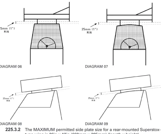
Any aerofoil/wing (including but not limited to its body, side-plates and mounting sliders) mounted on or above the cab MUST be mounted with at least a MINIMUM clearance of 1in (25mm) ABOVE the roofline at all points.225.1.5
In practice, any aerofoil/wing MUST be mounted high enough above the roof of the car such that a tube/pole/bar, 1in (25mm) diameter/ square in size, in a horizontal orientation is able to pass below both the side plates, the body and mounting sliders, and above the roll cage roof plate along the entire length of any overlap between the aerofoil/wing and the cab roof.This rule is illustrated in Technical Diagrams 06 to 09.225.2
Aerofoils225.2.1
The MAXIMUM permitted body-size for a top-mounted aerofoil is 44in x 44in (1117mm x 1117mm).225.2.2
The MAXIMUM permitted side-plate size for a top-mounted aerofoil is 48in x 24in (1219mm x 610mm) (length x height).225.3
Superstox-type wings225.3.1
The MAXIMUM permitted body-size for a rear-mounted Superstox-type wing is 48in x 18in (1219mm x 457mm) (transverse width x longitudinal depth).DIAGRAM 06 DIAGRAM 07
DIAGRAM 08 DIAGRAM 09
225.3.2
The MAXIMUM permitted side plate size for a rear-mounted Superstox-type wing is 26in x 12in (660mm x 305mm) (length x height).(Note: A decision on the outlawing of multi-deck wings/aerofoils has been deferred. These devices will be reviewed during 2014 with an appropriate ruling issued for 2015.)
226
Transponders226.1
All cars MUST be fitted with a transponder for electronic lap-scoring.226.2
The ONLY permitted transponder is the “Mylaps 260 Direct Powered”transponder.
226.3
The transponder MUST be fitted, and working, at all times when the car is on the track or being scrutineered.226.4
The transponder MUST be mounted a MINIMUM of 1800mm (1.8m) back from the front bumper, and approximately 450mm from the ground. Care should be taken to ensure a clear line of signal from the transponder to the ground.226.5
Transponders may be sold/transferred at any time; however, the driver MUST inform the Licencing Officer and complete a Transfer Form.226.6
Results will NOT be credited to a driver if their transponder fails tooperate from the start of the meeting.
226.7
Transponders are available from MYLAPS Sports Timing (www.mylaps. com) and HS Sports (www.hssports.co.uk).227
Driver/Car Identification227.1
The driver’s assigned racing number (as indicated on their licence) MUST be displayed on both sides and the rear of the car, and on both sides of any roof fin or aerofoil.227.2
The driver’s number MUST be black on a white background, in strokes of 1in (25mm) MINIMUM, to a MINIMUM height of 9in (228mm).227.3
The driver’s name MUST be displayed in letters at least 3in (76mm) tall on the off-side (right) of the aerofoil (or car body-panels if no aerofoil is fitted) where it can be CLEARLY seen by the spectators.227.4
Sponsor names and logos may appear on the car, but they must NOT interfere with the numbering or driver’s name.228
Grading Colours/Roof Painting/Lights228.1
The following official championship winning roof/roll-cage colours apply: • World Champion Gold• National Points Champion Silver
• British Champion Black/White chequered • European Champion Red/Yellow chequered
• World of Shale Champion Two Gold stripes, 100mm wide • World Cup Winner One Gold Stripe, 100mm wide • Shootout Champion Orange/White chequered
228.2
The following official grading roof/roll-cage colours apply:• Superstar/Star grades “Mail-box” Red
• ‘A’ grade Light Blue
• ‘B’ grade Yellow
• ‘C’ grade White
• Novice White, with a 75mm wide Black
Cross on the rear of the car
228.3
The whole of a top mounted aerofoil, if fitted, MUST be painted in the driver’s official grading/championship winning colour with the exception of the driver’s race number which MUST be black on white (see Car Identification rules above).228.4
The roof plate, roll-cage, and “ear” panels (from the waistline up) of a car using a top mounted aerofoil MUST be painted in EITHER:• The driver’s official grading/championship winning colour OR
• A neutral colour (i.e. NOT one of the colours listed above)
228.5
The whole of a top/rear mounted “Superstox-type” wing, if fitted, MUST be painted in the driver’s official grading/championship winning colour with the exception of the driver’s race number which MUST be black on white (see Car Identification rules above).228.6
The roof plate of a car using a top/rear mounted “Superstox-type” wing MUST be painted in:• The driver’s official grading/championship colour ONLY.
228.7
The roll-cage, and “ear” panels (from the waistline up) of a car using a top/rear mounted “Superstox-type” wing MUST be painted in:OR
• A neutral colour (i.e. NOT one of the colours listed above)
228.8
Superstar graded drivers MUST fit at least one flashing amber roof light in working order.228.9
External lights, flashing or otherwise (with the exception of Superstar graded lights), are NOT permitted.228.10
Any driver appearing with the wrong roof colour will be made to start at the rear of the grid in all races until the colour is rectified to the satisfaction of the Steward/Scrutineer/Clerk of the Course.229
Engines – General Rules For ALL Engines229.1
The engine MUST be mounted longitudinally in the chassis.229.2
The engine MUST be mounted in an upright position, as fitted to the vehicle of origin.229.3
The engine MUST be mounted centrally between the main chassis rails such that the rotational centre-line of the crankshaft sits along the centre-line of the car.229.4
Central fitment is measured by taking the distance from the inner edge of the main chassis rails to the rotational centre of the crankshaft pulley securing-bolt. This distance MUST be equal on both sides of the car to within a tolerance of +/-50mm, i.e. the two measurements MUST be within 50mm of each other, thus giving a maximum distance from the centre-line of the car to the rotational centre-line of the crankshaft pulley securing-bolt of 25mm.229.5
An oil catch tank with a MINIMUM capacity of at least 1-litre MUST be fitted to the car and connected to the engine’s breather system.229.6
Turbocharging and/or supercharging is NOT permitted.229.7
Fuel injection is NOT permitted.229.8
Electronic advance/retard and flywheel/crankshaft pickup systems are NOT permitted.229.9
Telemetry devices that are used to record engine data to enhance performance are NOT permitted.229.10
The following engines are permitted for use, subject to the individual specifications below:229.10.1
Any push-rod or side-valve water-cooled engine of Englishmanufacture up to an original capacity of 1300cc. (Note: This engine type will NOT be permitted from 2015 onwards).